Those who had to work with small parts, you know how hard it is to drill holes in them, the axes of which would be strictly perpendicular to the plane. The slightest imbalance leads to marriage, and often to breakage of the drill. Even the holes are not cylindrical in shape.
To avoid these troubles, I made on the base of the hand drill the drill press. Its design is very simple.
First of all about the materials. They need a little: a piece of chipboard with thickness of 20-25 mm, a small sheet of plywood with a thickness of 10 mm, the area made of aluminum with a size of 30X30 mm piece of a metal pipe Ø 20-25 mm from the wall 1.5—2 mm, and epoxy glue EAF-2 and epoxy putty.
Fig. 1. Drilling machine:
1 — base 2 — speed drill, 3 — guide tube 4 — slide 5 — hand drill 6 — socket for fixing the hand drill, 7 metal clamps.
To start working appropriate training dural corners of the slide. Make holes in them for the mounting M4 screws, and then secure both the clamp area, you can start making the holes for the guides. As in house conditions to use the drill bit Ø 25-30 mm is almost impossible, I recommend first to use a 10 – or 12-millimeter, and then counterbore the hole with a round file.
The next operation — installing guide tubes. They must be strictly vertical: failure to do so could nullify your efforts, therefore, recommend the following sequencing of activities. First base drill a hole for one tube any drill and knife give it a conical shape, as shown in figure 2A. Then insert the pipe (the latter must enter in the lower part of the hole with an interference fit) and using a square set it vertically. After that, the annular gap between the guide and the surface of conical holes fill with epoxy. The diameter of the second socket should be 2-3 mm bigger than the pipe (see figure 2B). Slip into the first guiding parts slide and using the latter as a conductor, insert into the slot the base of the second guide tube. The gap also pour glue and the whole structure, leave in this position to fully cure the epoxy.
Fig. 2. The scheme of fastening the guide tubes (A first, B second):
1 — guide tube, 2 — epoxy, 3 — Foundation.
For fixing the drill make a hole in the center panel of the slider. In addition, the RAM requires a special socket under the upper and lower ends of the frame of the drill. They can produce as follows. Put in the intended place of epoxy putty with a layer 1.5—2 mm, cover it with pieces of plastic film and, when the plaster harden slightly, select a drill and press it against the panel of the RAM. After the final curing putty polyethylene remove.
To the base of the machine, I attached two metal plates — with their help it is easy to fix the workpiece.
The machine is ready. It only remains on the Board of the Foundation bottom to glue four trim sponge rubber or polyurethane foam for greater stability and prevent slipping.
B. SERGEEV
Recommend to read “HINGE” THE ROVER The vehicle is made according to the scheme proven by the tractor "Kirovets". He has the same "breaking" the frame and drive on both bridges. What gives? First, the good permeability.... How to deliver a car to rent? Today we will discuss the question "How to deliver a car to rent?" and that is necessary for business organization. What are the benefits of this business? Who needs to rent a car? In... 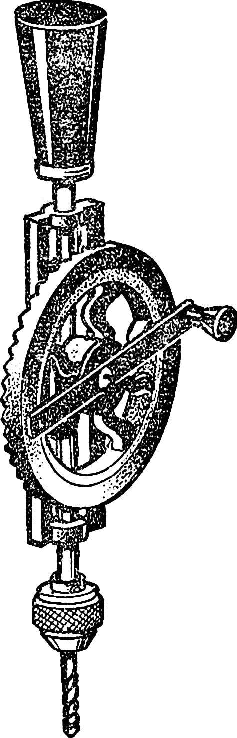
 Those who had to work with small parts, you know how hard it is to drill holes in them, the axes of which would be strictly perpendicular to the plane. The slightest imbalance leads to marriage, and often to breakage of the drill. Even the holes are not cylindrical in shape.