 Rare design can be build without the use of welding, particularly electric arc. This is why a good welder is a dream for many designers and enthusiasts. The “heart” of it — the welding transformer, which will be discussed. Winding step-down transformer (Fig. 1), connected to the original circuit (Fig. 2) provide arc stability. For welding use electrode Ø 3 mm, designed for AC current. (In the forced mode of the transformer it is possible to use electrodes with Ø 4 mm.)
From the secondary winding is permissible to remove voltage 50, 60, 70, 80 V with currents from 60 up to 150 A. the Exact value chosen through pairwise shorting the namesake of taps of the primary winding connected to the jacks.
Here are the data of our transformer. The cross section of the magnetic core 25 cm2. Two coils wound on separate cardboard frames without cheeks with a length of 260 mm internal Ø 65 mm placed at the Beginning of the secondary winding is 125 turns of copper bus-section 5X3 mm popstojanova isolation. It is located on top of the primary winding — 275 turns of insulated wire Ø 2,5 mm.
Both halves of the secondary winding are connected in parallel. And the voltage on it to increase to 60, 70 or 80, respectively, to reduce the primary winding. On her from both sides made the taps from 172, 197-th and 230-th turns.
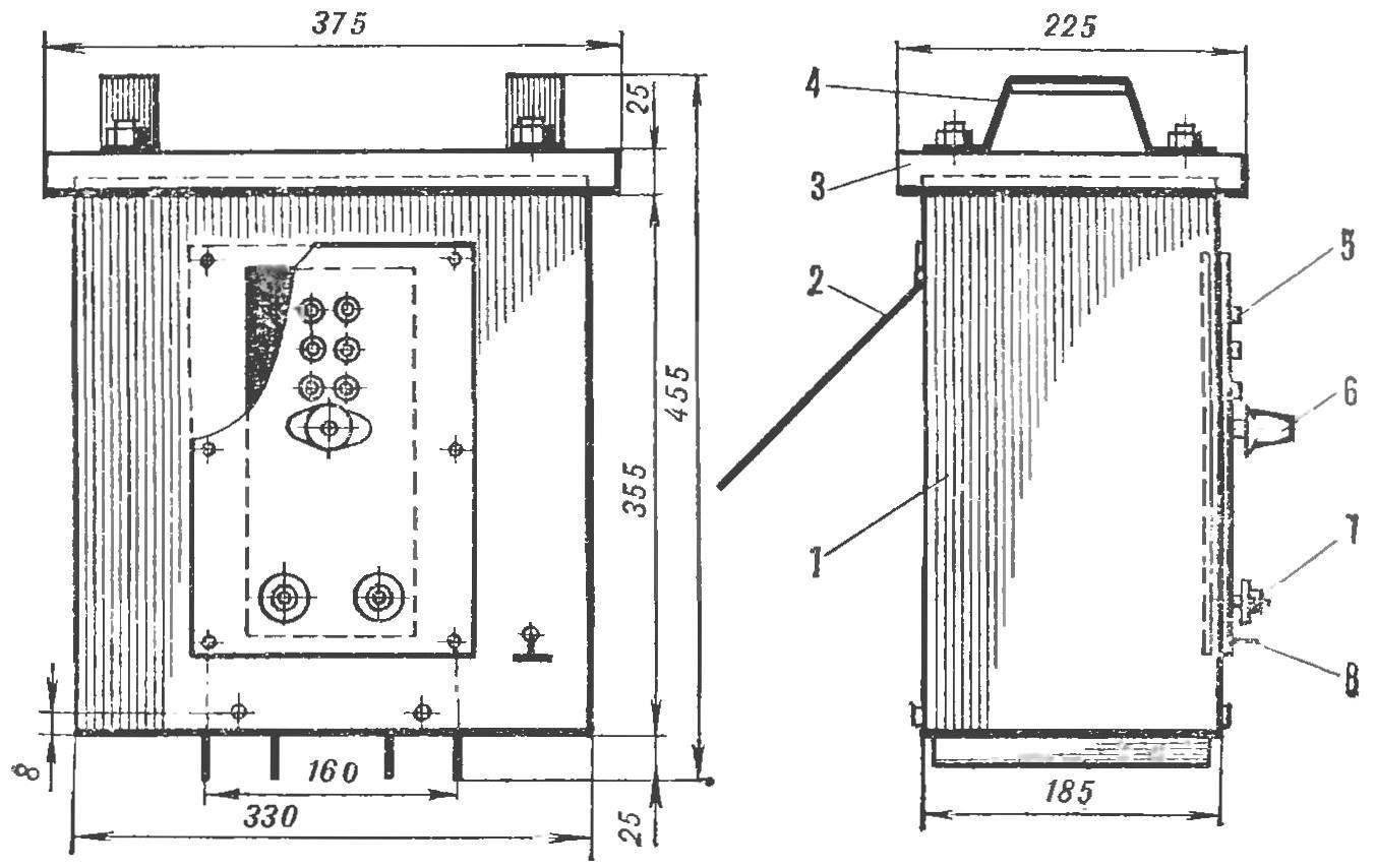
Fig. 1. Welding transformer:
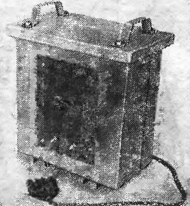
1 — housing 2 — cover the vent Windows, 3 — housing cover, 4 — handle, 5 — socket, 6 — plug, 7 terminal, 8 — bolt for grounding connection
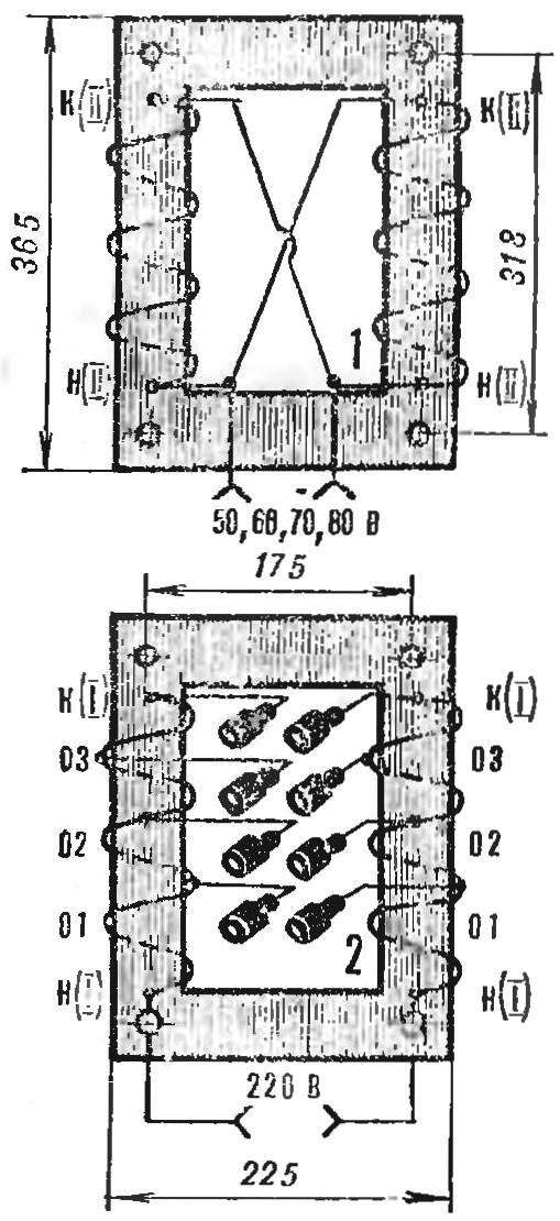
Fig. 2. Winding of the transformer:
secondary 1 and primary 2.
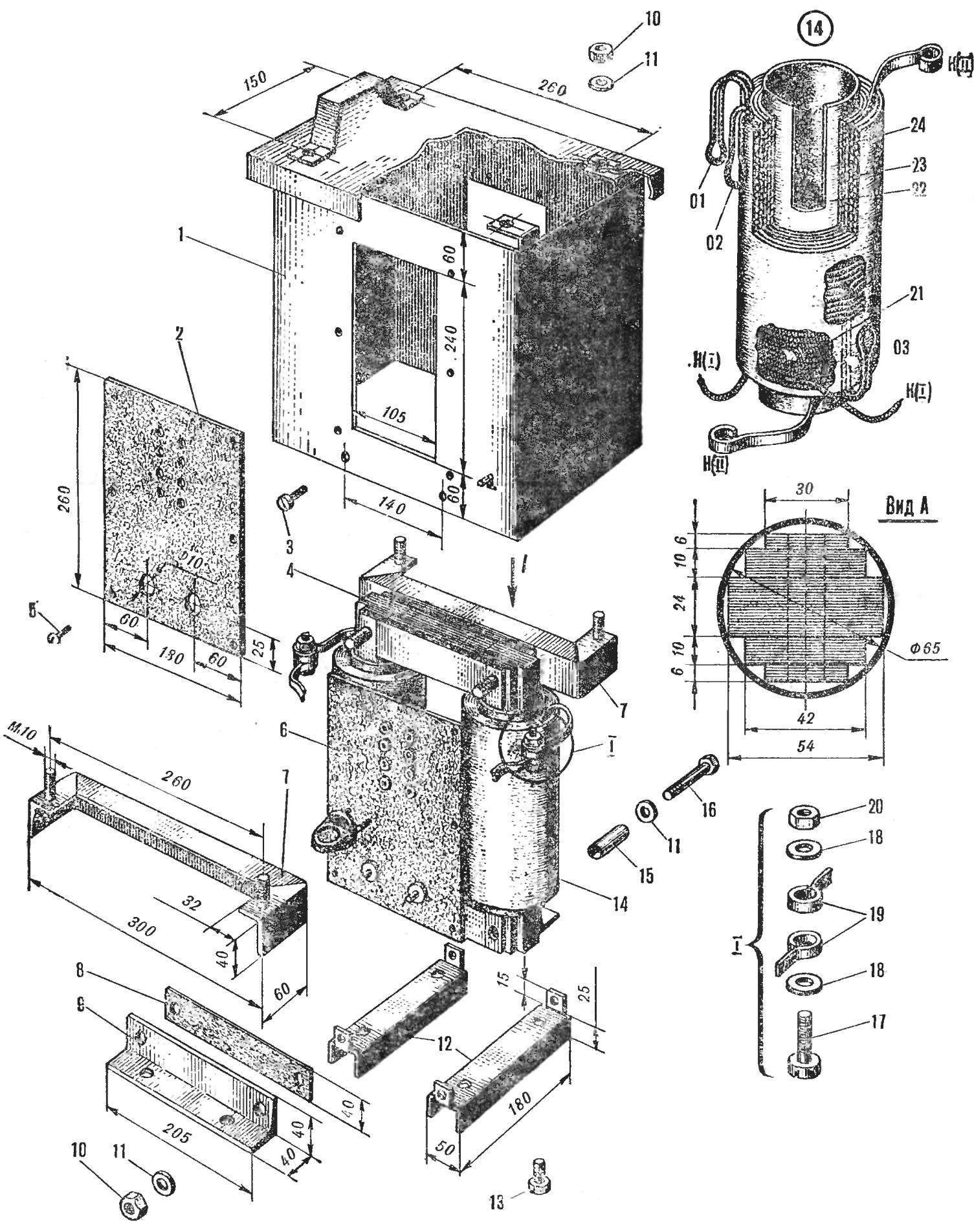
Fig. 3. The Assembly of the welding transformer:
1 — body, 2 outer panel (Micarta S-5), 3 — screw М5Х10, 4 — core, 5 — screw М4Х12, 6 — inner panel (Micarta S-5), 7 — a square top, 8 — pad (cardboard), 9 — gon, lower 10 nut M10, 11 — washer Ø 10 mm, 12 — base, 13 — bolt M10 * 20, a 14 — frame with windings, 15 — Bush (map), 16 — bolt М10Х70, 17 — screw М6Х18, 18 — washer Ø 6 mm, 19 — conclusions of the secondary winding 20 nut M6 21 — cotton lace, 22 — frame 23 — a secondary winding 24, primary winding.
The transformer has a “margin of safety”. So the short-term inclusion in the network winding with a low amount of turns on its efficiency is not appreciably affected. The turns of both windings are placed in a clockwise direction, laying between 3 to 4 layers of paper, and the findings reinforce the cotton braid. Pre-made coils (Fig. 3) need to be impregnated with bakelite varnish and dried thoroughly.
The order of Assembly of the transformer shown in figure 3. The yoke is pulled with the bolts M10 and covered for protection from corrosion bakelite puck. The terminals of the windings should be thoroughly zaludit.
The casing is welded from steel sheet of thickness 1 — 1.5 mm. In the front wall made of rectangular slot kamnica, and on the back — the ventilation window of size 180X150 mm.
When the 15— 20 electrode Ø 3 mm, the heating temperature of the windings shall not exceed 70°.
V. ZAYTSEV, engineer
Recommend to read
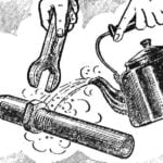 UNSCREWS… BOILING WATER
Intractable loosening the tubular connection experienced craftsmen heated with a blowtorch. Almost the same effect can be achieved and more domestic. Spraying the connection with boiling...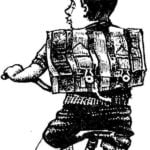 SATCHEL — NOT A FOREIGNER
Some just "containers" for books not used by students going to school, from stylish backpacks and briefcases to canvas bags, and plastic bags. But if high school students is allowed...
