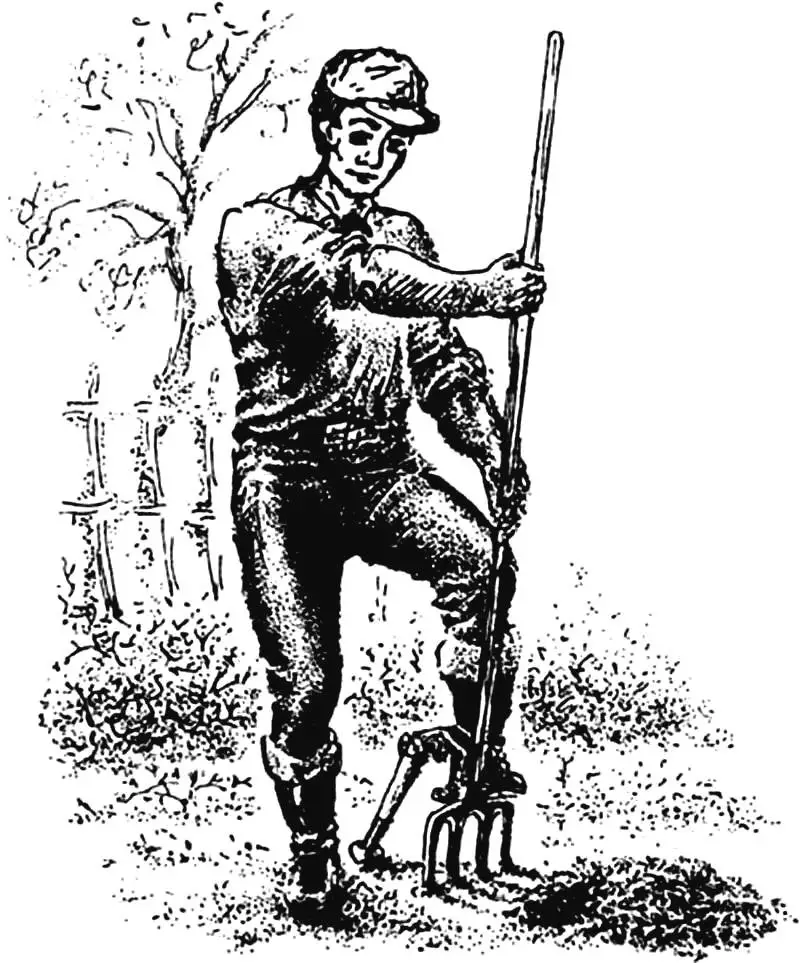
This is not about dancing in the garden beds, but about an original garden-and-vegetable tool that makes labor-intensive work—performed for ages with a spade (at best—with special forks)—possible even for elderly people (the author and test person of this design is already over seventy).
Despite the “tortured” “formula of invention” by the patent office—“A device with a lever, the support point of which, moving forward and backward along a short arc of a circle, at the same time—via a supporting-and-pivoting stand—does not lose constant contact with the ground throughout each working cycle”—the lever garden digger (ROK) is quite simple, reliable, and accessible to make in a modest home workshop. In essence, it is a modified garden-and-vegetable fork equipped with a pivoting-locking knee, a pedal, and a lever-hinged mechanism with a supporting-and-pivoting stand.
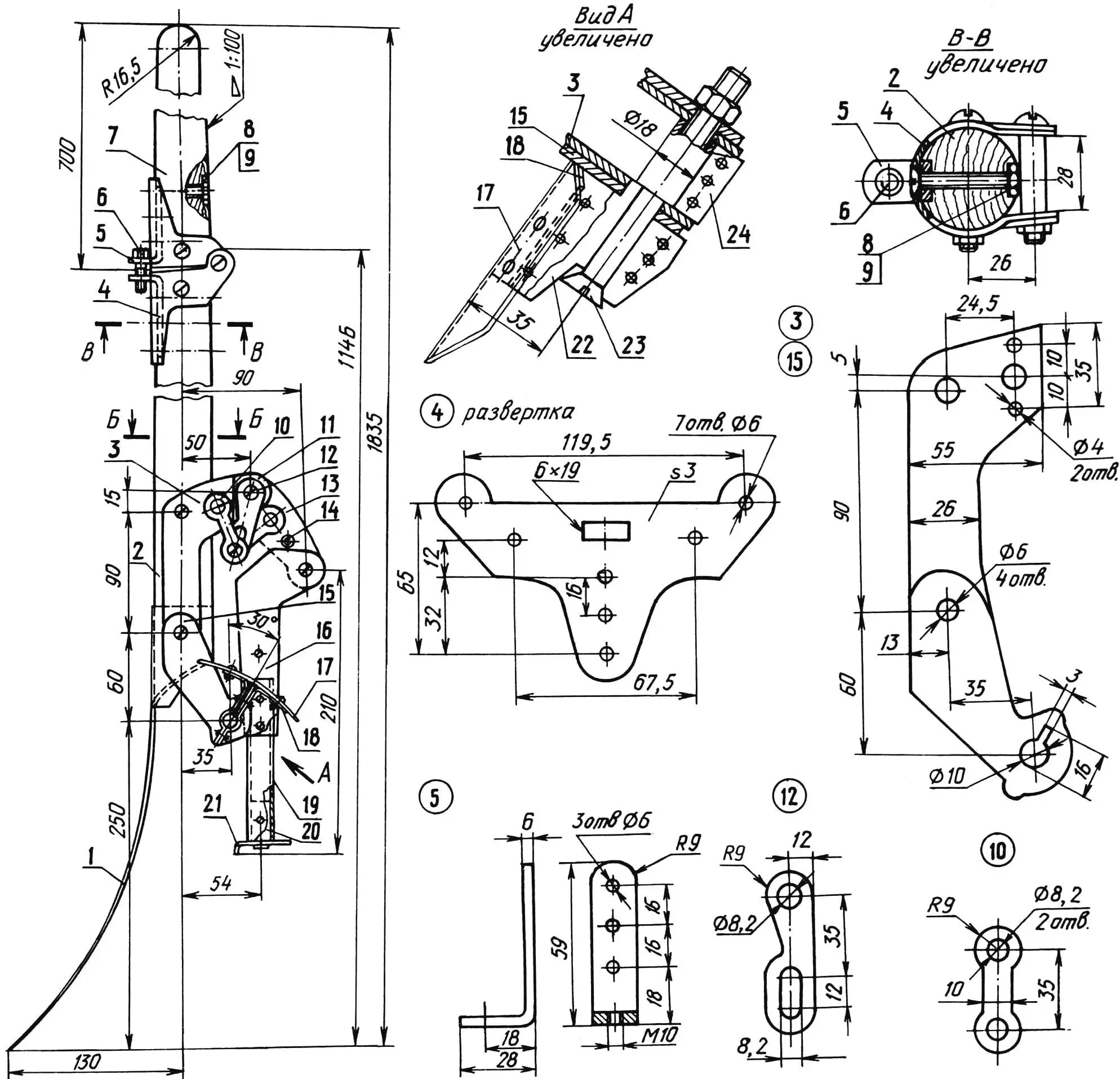
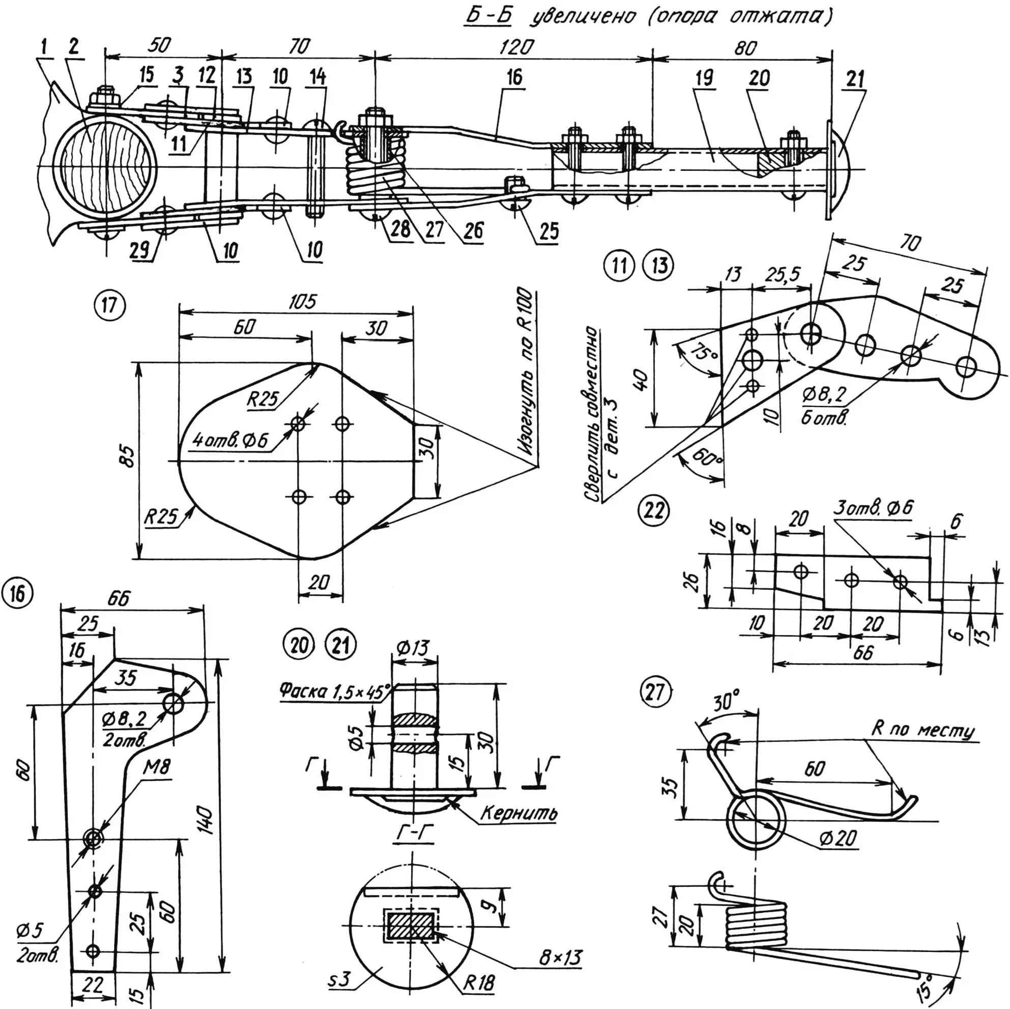
1 — spade tip (modernized garden-and-vegetable forks), 2 — lower handle section (dried willow Ø40, L875), 3 — base (2 pcs.), 4 — pivoting-locking knee section (2 pcs.), 5 — tie bar (St3, 2 pcs.; on the upper one, instead of thread M10 an Ø10.2 hole is made), 6 — screw M10, 7 — upper handle section (dried willow Ø40, L700), 8 — bolt M6 with a countersunk spline head (6 pcs.), 9 — nut M6 (11 pcs.), 10 — small eye strap (4 pcs.), 11 — upper reinforcement plate (2 pcs.), 12 — large eye strap (2 pcs.), 13 — pivot bracket (2 pcs.), 14 — stop pin (peened/countersunk M8 bolt), 15 — lower reinforcement plate (2 pcs.), 16 — pivot stand (2 pcs.), 17 — pedal, 18 — profiled bracket (2 pcs.), 19 — support post (duralumin or steel tube 16×2.5), 20 — tip (duralumin or steel rod Ø13), 21 — replaceable shoe, 22 — reinforcement shim, 23 — pedal axis (bolt M10 with nut), 24 — sleeve-crimp coupling, 25 — spring stop (screw M8), 26 — bushing (duralumin or steel tube 12×2, 2 pcs.), 27 — spring (steel wire Ø2.5), 28 — bolt M8 with nut (3 pcs.), 29 — rivet half-axle (4 pcs.). Material for parts 3, 4, 10—13, 15—18, 21, 22 and 24 — duralumin (sheet s3) or “stainless steel” (sheet s2).
Most ROK parts are made from sheet hard duralumin 3 mm thick. Although a 1.5 mm steel sheet can also be used, for example “stainless steel”. In that case the tool will be heavier—up to 3—3.5 kg—but more long-lasting.
For the handle made of two parts, willow is best suited (segments of straight branches whose diameter is slightly greater than the one specified in Fig. 1). After drying, it only remains to round it with a plane and clean it with a rasp.
Both sections of the pivoting-locking knee, as well as parts 17 and 18 of the pedal unit, are made using patterns followed by bending and crimping (on mandrels of the appropriate diameter) in a vise. When drilling elements of circular cross-section, a jig is used: a section of an angle with a set of holes for the most commonly used diameters (sketches of similar fixtures have been published in the journal under the heading “Tips from around the world”).
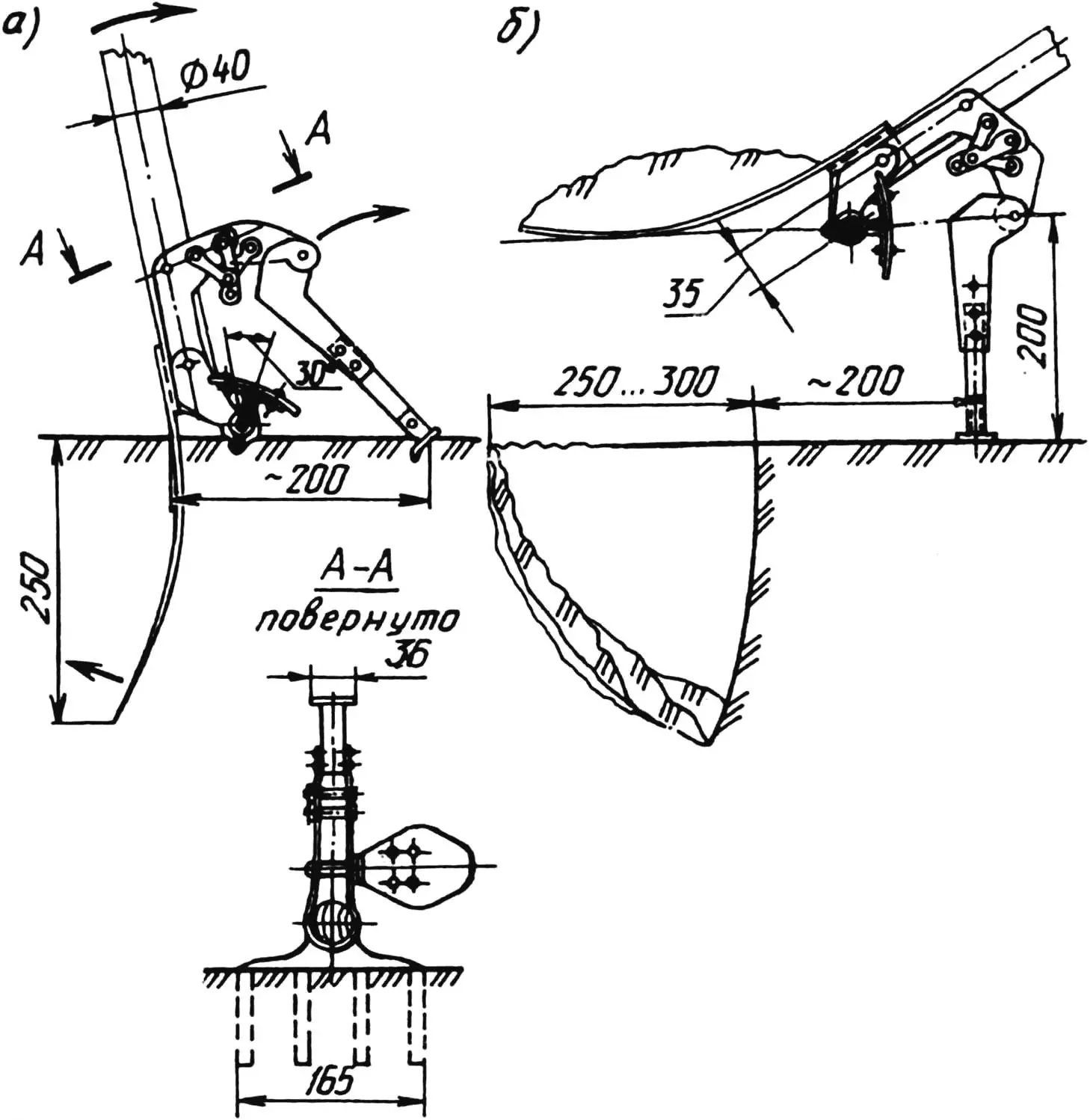
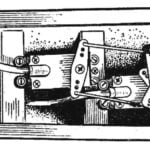
a — start, b — end.
The homemade tool is designed so that converting it from the folded state to the working state takes very little time. You only need to unfold both halves of the lock unit by 180° and fix the straightened handle with a tie screw; then move the support leg away (in this case the shoe will be located 200 mm from the handle axis) with subsequent fixing of parts 10—13 using tightening nuts.
Now about how the soil is processed with the ROK. Dig while standing upright and pressing the pedal with your left foot. Place your left hand on the handle in front of your right hand, closer to the spade tip (for left-handers, everything is the other way around). At this time, the pivoting-locking knee of the mechanism is moved to the length of the outstretched forward right arm, which ensures the easy entry of the point into the ground (Fig. 2a). Then, smoothly pulling the handle toward yourself, you create for the Archimedean lever—the tool becomes a garden-and-vegetable instrument at that moment—the support point and transfer the full weight of the separated soil layer onto the tubular stand with the replaceable shoe. With further tilting of the “top,” the movement of the buried “bottom” (Fig. 2b) becomes more and more similar to the work of an excavator, whose bucket is carried forward with the subsequent dumping of the removed soil.
«Modelist-konstruktor» № 12’97, Y. MEDVEDEV
Recommend to read
 CONTROL SYSTEM
New technology for the manufacture of model airplanes, primenyal the modelers of the GDR from the city of Erfurt, the magazine introduces readers to No. 6 in 1977. Today we tell about...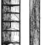 SKYSCRAPER FOR POTS
In a closed wall shelves and kitchen table-Cabinet to store awkward bulky utensils such as pots, pans, colanders, and modern means of mechanization: sokovarki, mixers, food...
