There are a huge number of people dreaming of building walk-behind tractors, snowmobiles, microtractors, and cars. The number of devices under construction is tens of times less, not to mention the number of those built, much less operational. As a result, amateur designs that have been completed and work flawlessly are rare.
The designs of microtractors, despite their apparent simplicity, require no less serious approach and thorough development than, for example, microcars or UAVs. It is no coincidence that home-made workers most often focus on a ready-made model, trying to copy it exactly, and are less likely to engage in technical creativity and independently search for solutions. This is understandable: the proven design allows you to achieve the desired result faster. This explains the interest in walk-behind tractors, for example, by V. Arkhipov from Kaluga (see “M-K” No. 6, 1982 and No. 1, 1984) and many other means of small-scale mechanization published in the magazine.
A more complex, but more appropriate path to your capabilities and characteristics is to independently develop the equipment you need for your garden or vegetable garden. Its design must begin with a precise definition of the requirements for it, the means and methods for their implementation.
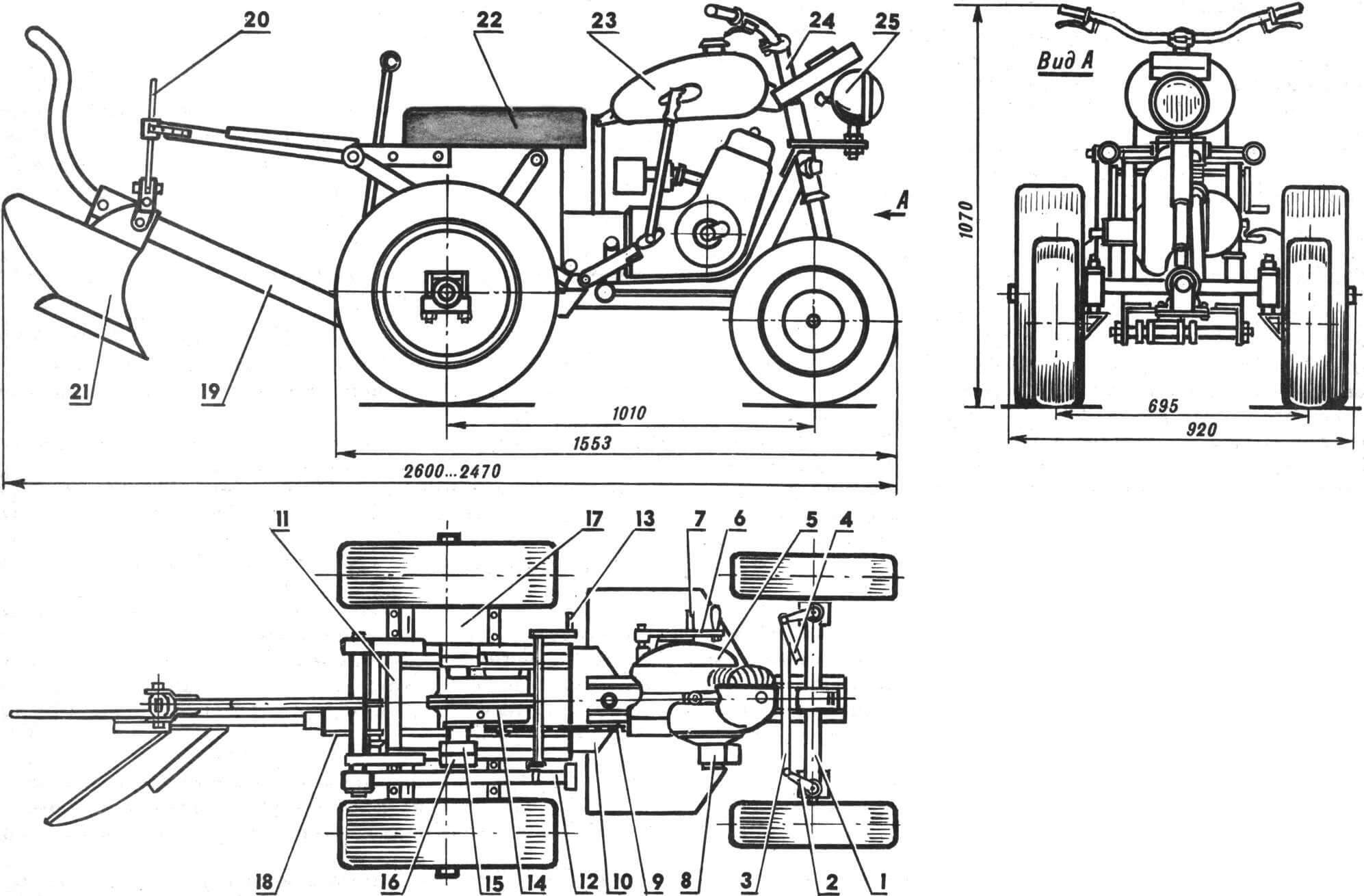
1 – front axle, 2 – steering lever, 3 – steering linkage, 4 – steering linkage, 5 – T-200M engine, 6 – engine start lever, 7 – gearbox control lever, 8 – magneto, 9 – chain, 10 – front part of the frame, 11 – rear part of the frame, 12 – double-arm plow lifting lever, 13 – automatic lever lock plow lifting, 14 — main gear (differential) from the S3A motorized stroller, 15 — rubber-metal coupling, 16 — band brake pulley, 17 — final drive, 18 — plow suspension, 19 — plow drawbar, 20 — plow lifting rod, 21 – plow, 22 – seat, 23 – fuel tank, 24 — steering column, 25 — headlight. The fuel tank, seat, and steering column are not shown in the top view.
We highlight the main points: type of work performed, weight, alignment, engine and units used, layout solution, wheel arrangement, gear ratios, operational speeds, speed when cultivating land, transport speed, etc. In this case, approximate calculations are quite sufficient. A sketch and ergonomic study of the future design on a scale of 1:5 or 1:10 would also not hurt.
Do not try to introduce many original, but untested technical solutions into a new design. Let 90 percent of it be already proven layout, components, assemblies, and materials. Thoroughly study and work on analogues; try to use well-repaired or new engines, transmissions, and other components and assemblies.
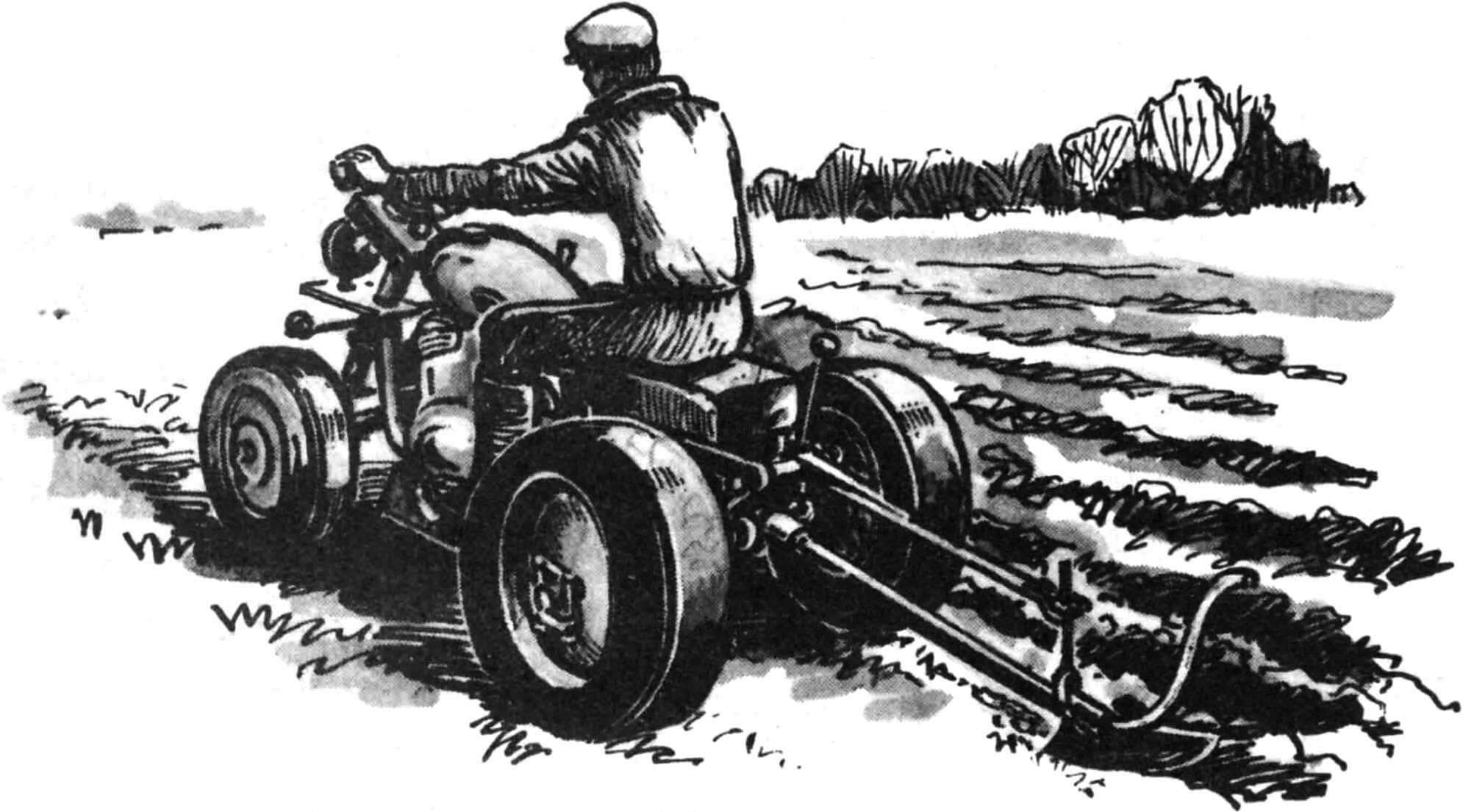
This is exactly how the proposed microtractor was built, intended for plowing light soil (vegetable gardens) and for transporting a trailer with a total weight of up to 500 kg. Its design, as it developed, underwent a significant evolution: in 1976 – the first version in the form of a walk-behind tractor, in 1977 – its modification, in 1977 – 1978 – transformation into a three-wheeled microtractor, in 1980 – a four-wheeled version with a swinging front axle.
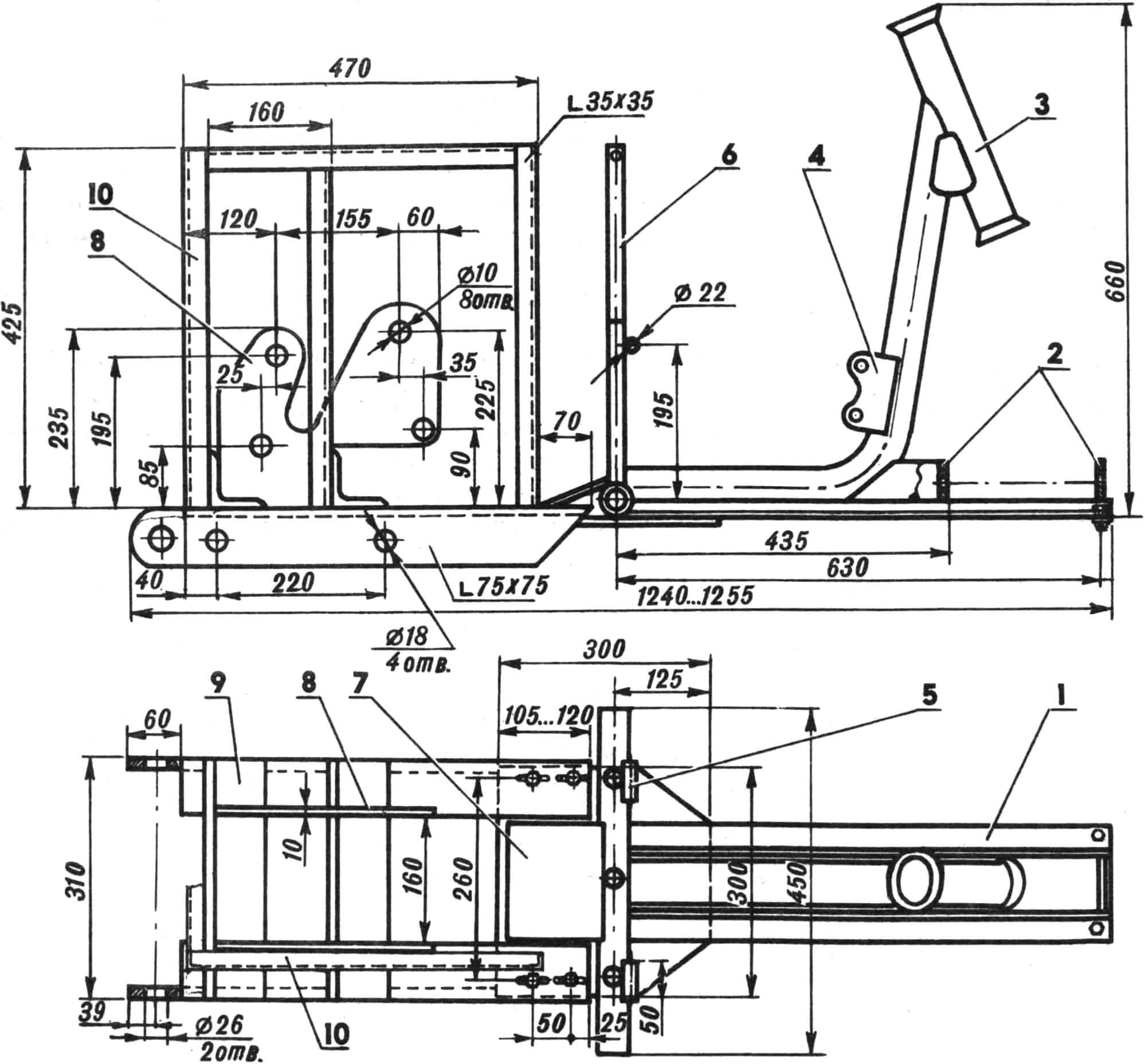
1 — front half-frame, 2 — brackets for the swing axle of the front wheels, 3 — part of the frame, borrowed from the T-200M scooter, 4 — front engine mounting bracket, 5 — mounting bracket for the sub-engine frame, 6 — rack for mounting the fuel tank, 7 — reinforcement front half-frame plate, 8 — final drive mounting bracket, 9 — rear half-frame, 10 – upper part of the rear half-frame.
The microtractor is distinguished by high-speed motorcycle-type steering, in which the steering wheel interacts directly with the front wheels through a lever and rod. This solution provides excellent maneuverability. This is also facilitated by the separate drive of band brakes and the short wheelbase of the microtractor.
The main technical solutions are quite traditional. The engine located at the front is connected by a chain drive to the rear axle differential gearbox from a cargo scooter (gear ratio 1.8). The torque from the differential is transmitted to the output shafts of the final drives (i=3.75) with brake pulleys. The engine crankshaft speed is in the range of 2200-2800 rpm. The proposed mode provides optimal fuel consumption and the longest engine life. The output shafts of the gearboxes are equipped with wheels from a VAZ-2103 car. Front wheels from a scooter.
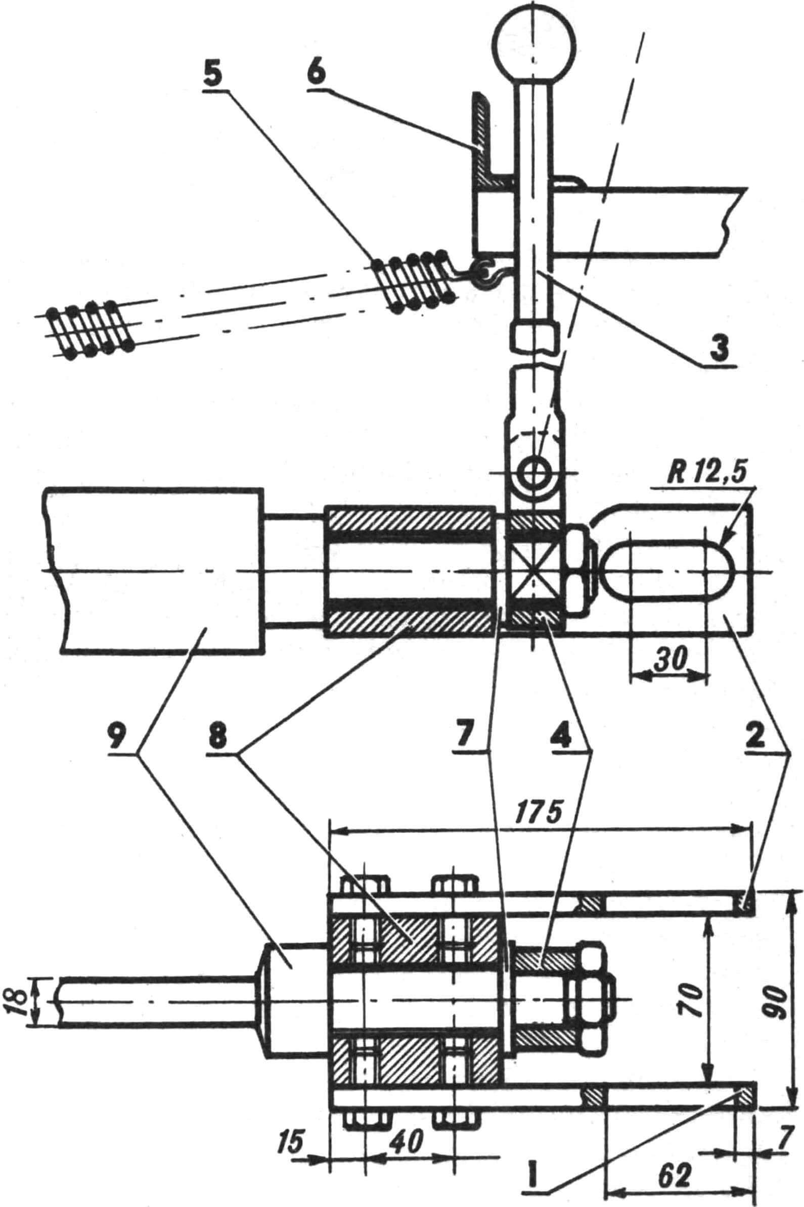
1 — right suspension cheek, 2 — left suspension cheek, 3 — plow tilt lever, 4 — plow tilt lever bracket, 5 — plow tilt angle lock spring, 6 — plow tilt angle lock, 7 — support washer, 8 — plow suspension housing , 9 – plow drawbar.
The microtractor uses a single-horse plow, which has a “floating” mount and adjustment for the thickness of the captured layer (plowing depth), as well as for the angle of inclination. The double-arm lever facilitates lifting the plow (with automatic locking in this position), as well as its forced deepening. The free single-point suspension of the plow allows the microtractor to move curvedly when plowing. The plow is mounted 80-120 mm to the right of the axis of symmetry of the microtractor.
The microtractor frame is welded from angles and consists of two halves connected by bolts. By moving one part of it relative to the other, you can adjust the chain tension. The sub-engine part of the frame and the steering column are used from a T-200M scooter, the steering wheel is from a Java-634 motorcycle. The magneto installed on the engine provides reliable sparking, as well as power supply for the side lights and turn signals of the microtractor. .
The weak point of the unit can be considered the rear differential gearbox from a cargo scooter, since a significant part of the time it works with loads close to the maximum, and therefore constant monitoring of its condition is required.
TECHNICAL CHARACTERISTICS OF THE MICROTRATOR
Weight, kg 270—340
Engine type T-200M
Power, l. With. 8
Transport speed, km/h 8—12
Operating speed when plowing, km/h 3—3.5
Operating fuel consumption, l/h 2—3
Number of gears:
forward 4
back 4
Wheel formula 4X2
A. KOPYEV, P. KOPYEV, Beloretsk
