Not so long ago, after retiring, I seriously took up beekeeping. However, our region is not rich in honey-bearing plants, so during the season, I have to move the entire apiary from one place to another six or seven times.
To transport the hives, I built a trailer for my Izhevsk pickup Izh-27151-01, on which eight hive bodies can be installed. Such capacity is ensured because, for a passenger car, the trailer is quite unusual — it’s a twin-axle design.
When making the trailer, I used many parts and assemblies from decommissioned vehicles and agricultural machinery. Taking into account the time for design and finding the necessary parts and materials, I completed the trailer in two months.
The trailer has a frame structure. Both axles have their own separate subframes, which are connected to the main frame. All parts of these assemblies are made of rectangular steel tubes with a 60x40x2 mm cross-section and welded together.
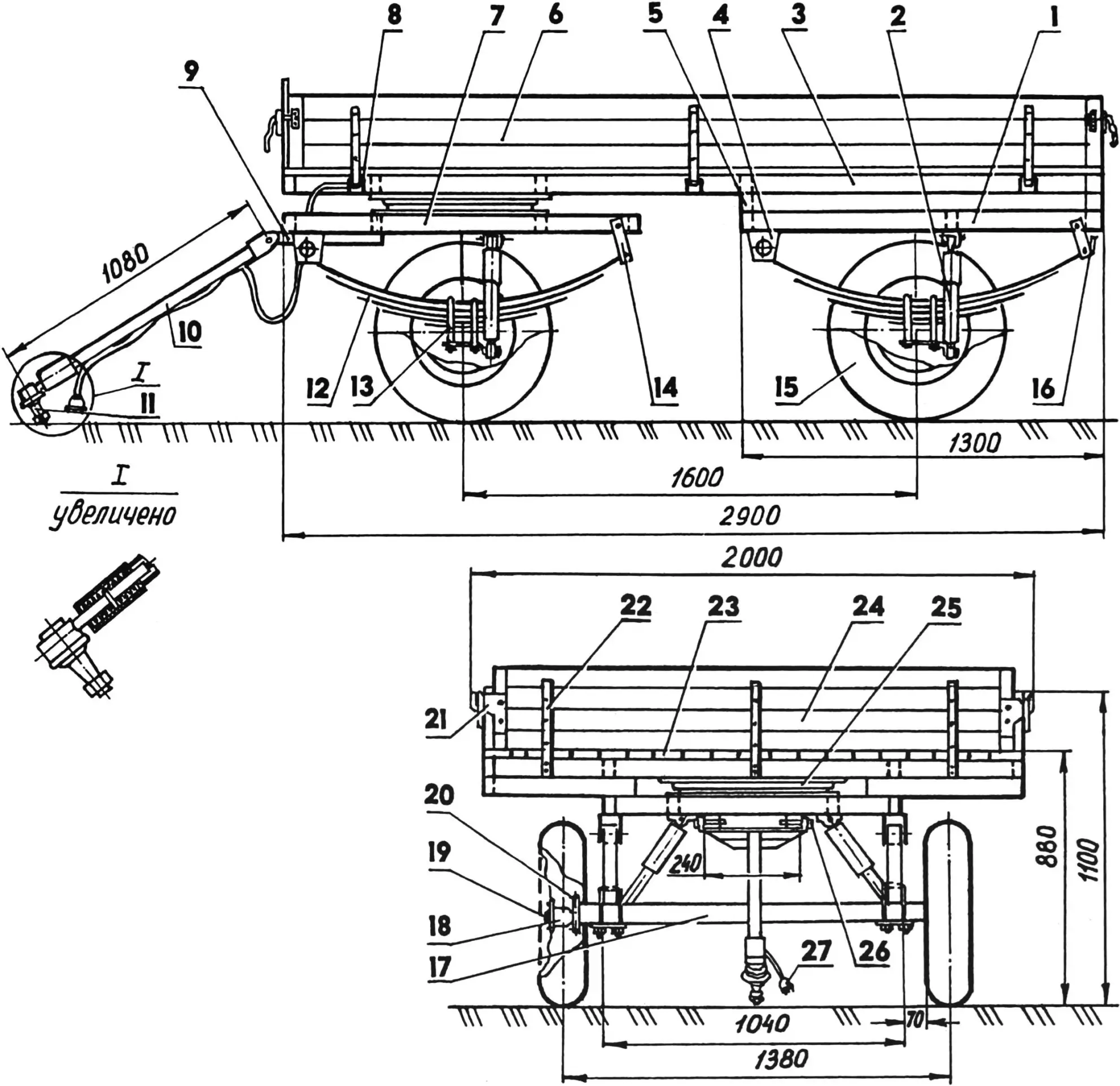
1 — rear subframe; 2 — shock absorber (4 pcs.); 3 — frame; 4 — bracket (St3, 3 mm sheet, 4 pcs.); 5 — spacer; 6 — side folding board (20 mm board, 2 pcs.); 7 — front subframe; 8 — hinge (St3, 25×4 strip, 9 pcs.); 9 — longitudinal rod (square tube 40x40x3, 2 pcs.); 10 — drawbar (square tube 40x40x3); 11 — tip (from the steering of the “Belarus” tractor); 12 — spring (4 sets); 13 — U-bolt (8 pcs.); 14 — shackle (4 pcs.); 15 — wheel (4 pcs.); 16 — combined signal light (2 pcs.); 17 — axle beam (steel tube 60x60x4, 2 pcs.); 18 — wheel hub; 19 — flange shaft; 20 — axle flange (St3, 8 mm sheet); 21 — lock (from UAZ-452 vehicle); 22 — stand (12 pcs.); 23 — flooring (30 mm board); 24 — front board (20 mm board); 25 — turntable (from FN-1 forage distributor); 26 — drawbar connecting pin (St3, Ø20 rod, 2 pcs.); 27 — rear light wiring connector;
parts 1, 3, 5, 7 are made of 60x40x2 tubes;
parts 2, 12, 13, 14, 15, 16, 18, 19 are from the “Moskvich-412” car
The rear subframe is rigidly connected to the main frame — welded through transverse console spacers made of the same tube.
The front subframe is connected to the frame via a hinge — through a turntable. This unit was taken from a decommissioned FN-1 agricultural forage distributor. The turntable consists of two rims (upper and lower) with ball bearings rolling freely between them along their tracks. The unit is lubricated with grease. The upper rim is attached to the main frame, and the lower one — to the rotating subframe. For this, two crosspieces made of the same 60x40x2 rectangular tube are welded to the front of the frame and to the middle of the subframe. The rims are bolted to the crosspieces with M18x55 bolts (with washers and nuts). The reliability of this unit is beyond doubt since it operates under even harsher conditions in its original application.
Both front and rear wheel suspensions of the trailer are made based on the rear suspension of the Izh-27151-01 towing vehicle. Therefore, some factory-made parts from the “Moskvich” car were used: shock absorbers, springs, U-bolts, shackles, and others.
The spring brackets are made of 3 mm steel sheet and welded to the front parts of the subframes. In the rear, the brackets are connected by hinged shackles.
As wheel axles, I used spindle hubs from the front wheel struts of the “Moskvich” car, with the upper and lower struts cut off, leaving only the hubs with flanges.
The bridge beams (both front and rear) are made from thick-walled square tubes 60x60x4 mm. Steel rectangular plates measuring 140x80x8 mm are welded to their ends. Holes matching those on the wheel hub flanges are drilled in the corners of the plates. The bridge flanges and wheel hubs are bolted together using the same bolts as on the base vehicle. The wheels and hubs with bearings are also from the Moskvich.
Since the hives with bees to be transported are a very delicate load, the suspension of the trailer axles was made soft — spring-based. To prevent excessive shaking on rough country roads and off-road, shock absorbers were also added to the suspension.
The towing hitch consists of two longitudinal rods, a drawbar, and a tip.
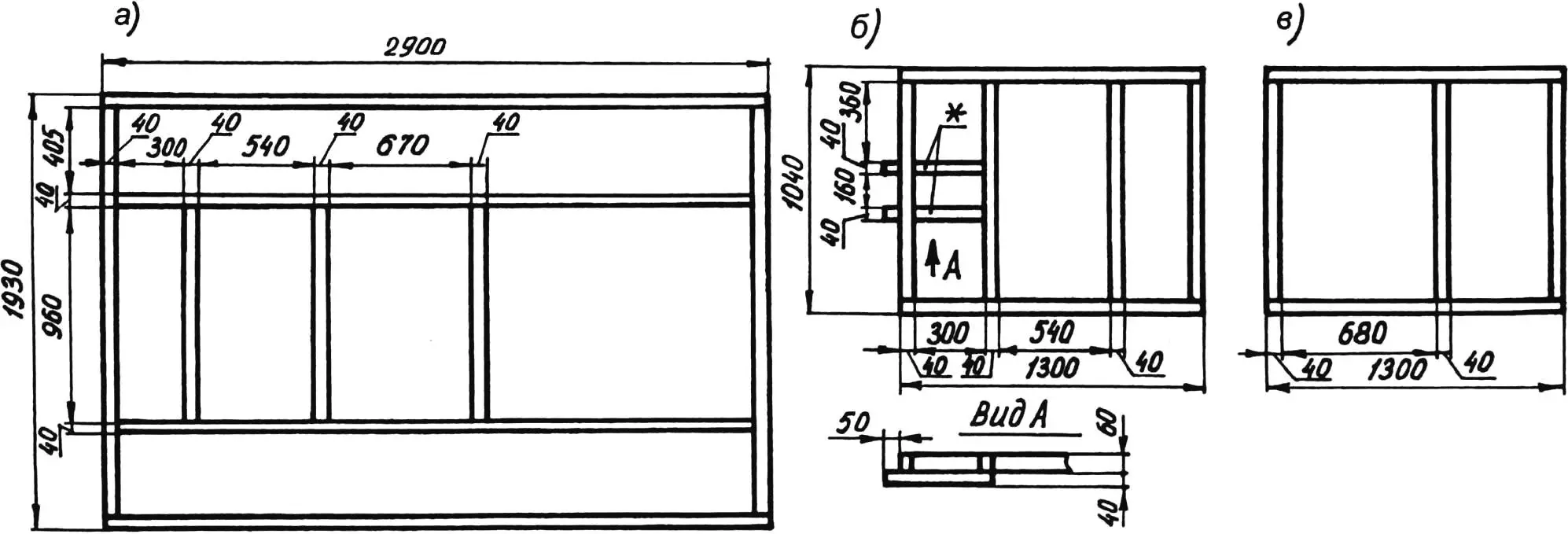
a — frame; b — front subframe; c — rear subframe;
frame and subframe parts are made of 60x40x2 tubes;
parts marked * are made of 40x40x3 tubes
The longitudinal rods are made of 40x40x3 square tubes and welded to the underside of the rotating frame. The drawbar is a welded structure consisting of a crossbar (steel angle No.7), the drawbar itself (steel square tube 40x40x3), and a damper housing (a hollow cylinder with holes in the end walls). The damper helps to soften impact loads from the trailer on the car’s body and transmission, especially during starting and braking.
At the ends of the drawbar crossbar, the horizontal shelf is cut off, and the remaining vertical parts are bent backward at 90°, forming lugs. Corresponding holes are drilled in these lugs and the front ends of the rods, and the parts are connected by steel cylindrical pins.
The damper consists of a rod with a flange in the middle, with normally extended springs on both sides, all placed inside the housing. My design is a welded, non-detachable construction — not the most convenient one, so the diagram shows only the operating principle.
The outer end of the rod is connected via a cylindrical adapter to a perpendicular tip taken from the steering system of the “Belarus” tractor. It’s a conical pin with a thread on the thinner end. Before towing, the tip is inserted into the conical hole of the towing bracket on the car.
For driving safety, two combined lights with tail, turn, brake, and reverse lamps are installed at the rear of the trailer. The wiring runs inside one of the longitudinal frame tubes and connects to the car’s electrical system through a multi-pin connector.
The trailer bed is made of tongue-and-groove boards 30 mm thick. The boards are clamped at the front and rear of the platform with 25×4 mm steel strips, bolted to the frame with M6x75 bolts every 300 mm.
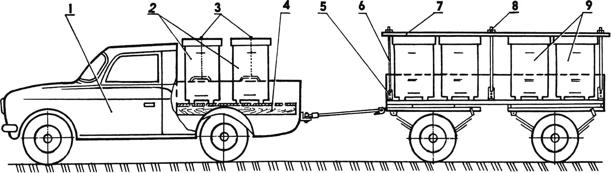
1 — vehicle; 2 — hives on the vehicle (4 pcs.); 3 — nylon rope ties (4 pcs.); 4 — truck bed flooring (30 mm board); 5 — bracket (St3, 4 mm sheet, 6 pcs.); 6 — tightening rod (Ø12 rod, 6 pcs.); 7 — clamping plank (30 mm board, 2 pcs.); 8 — M12 nut and washer fastener (6 pcs.); 9 — hives on the trailer (8 pcs.)
The trailer is equipped with wooden sides made of 20 mm tongue-and-groove boards. The boards are bolted to the uprights (three per side) with M6x30 bolts. The front board is fixed — its uprights are welded to the front crossbeam of the frame. The remaining boards are folding; their uprights are attached to the frame with hinges made of 25×4 mm steel strips. In the raised (closed) position, the boards are locked with latches taken from an old UAZ truck.
The scheme for fastening the hives on the trailer and in the pickup body is shown in the diagram. A removable wooden floor made of 30 mm thick boards on two beams was built for the vehicle body. Its height matches the wheel arch protrusions above the bed floor. The platform allows for placing four hives and all beekeeping equipment. The hives in the vehicle bed are secured with nylon rope ties.
The trailer easily accommodates eight hives. Since the hives are not removed from the trailer at the apiary (the place of long-term standing for nectar collection), their fastening here is more secure — using wooden rails and tightening steel rods. The rods have hooks on one end that catch into holes in the brackets bolted to the trailer floor. The other end of each rod passes through a hole in the rail and is tightened with a nut from above.
At the apiary, the trailer sides are folded down. The platform area allows easy servicing of the hives directly on the trailer.
It goes without saying that the trailer can also carry any other types of cargo — both individual and bulk.
I. SHEVCHENKO
Recommend to read
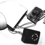 Protective sensor
Motion sensor DD-010 disassembled with the control board removed and an additional siren (100 dB sound level) type KPS-4510 connected. Motion sensors (DD) based on Fresnel lenses and...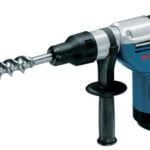 Choose quality tool
Original and counterfeit: don't buy a poor quality tool. When you select the tool great a risk to run into an unscrupulous seller, and is reliable and durable products of the famous...
