
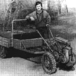
Aviation mechanic M.A. Masterov is one of that remarkable group of amateur designers that the Udmurt land has always been proud of. His achievements include such serious works as delta- and motorized deltaplanes, an aircraft of his own design and a restored Yak-18T, various machine tools, and much more. Today, all the craftsman’s efforts are directed toward completing the assembly of a small wheeled tractor, and we offer readers to familiarize themselves with one of his developments—the “Krot” (Mole) motorized winch. This topic has been raised more than once in the pages of our magazine, but it remains relevant to this day, as in most regions and cities the administration meets residents halfway by allocating land for farming. We think that such a universal unit will be an indispensable assistant in many tasks.
Simplicity in manufacture and operation, lightness, compactness, and versatility are the main advantages of this device. Of course, its main purpose is plowing the garden, but with a system of blocks it can be used as a means for lifting and moving loads.
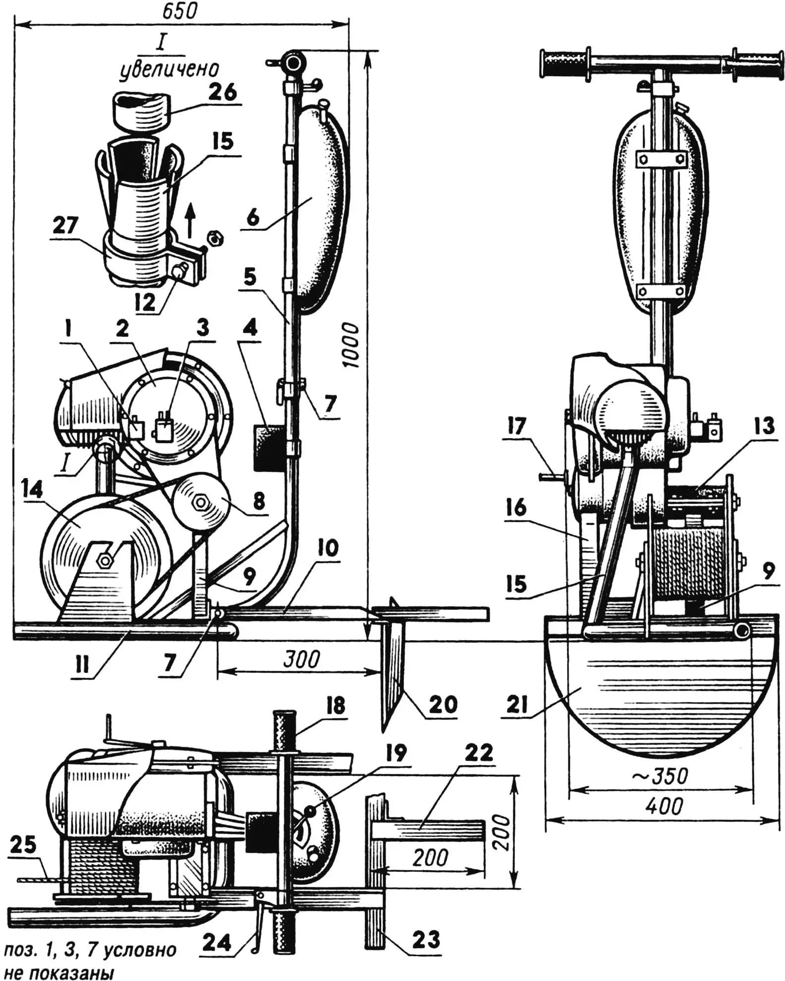
1 — fuel pump, 2 — T-200 engine, 3 — carburetor, 4 — electrical box, 5 — upper boom section (St3, pipe 33.5×2.8), 6 — fuel tank (from moped), 7 — marine bolts (Ø8), 8 — drive sprocket (z=19, from “Izh-Jupiter”), 9 — main engine support, 10 — anchor pull (St3, angle 25×25, L300), 11 — frame, 12 — M5 bolt, 13 — half-clamp, 14 — driven sprocket (z=42, from “Izh-Jupiter”), 15 — exhaust support, 16 — auxiliary engine support, 17 — kick-starter lever, 18 — throttle handle, 19 — gear shift lever, 20 — anchor stop (St3, angle 25×25, L400), 21 — anchor (from tractor cultivator disk), 22 — lever (pipe 25×25), 23 — crossbar (angle 25×25, L400), 24 — clutch lever, 25 — cable (steel, Ø4), 26 — engine exhaust pipe, 27 — clamp.
The reliable, sufficiently powerful, and relatively small T-200 engine (10 hp, from the “Tula” motor scooter), with a forced air cooling system, served the designer as the basis for the motorized unit. The T-200 itself was not modified, except for the output shaft housing, which was turned down to a diameter of 80 mm for mounting on the frame. The engine is in an inverted position compared to the standard installation, as this is not critical for it (due to the absence of a special lubrication system for internal mechanisms in motorcycle-type engines, their crankcases do not necessarily have to be at the bottom). It is connected to the frame at three points: with the auxiliary support, the exhaust pipe, and with the main support. At the first point, the engine simply rests on the support cradle, at the second—the pipes fit one into the other and are clamped with a clamp, and at the third—the output shaft housing is rigidly fixed with a half-clamp. The fuel supply and control systems are similar to those of the motor scooter.
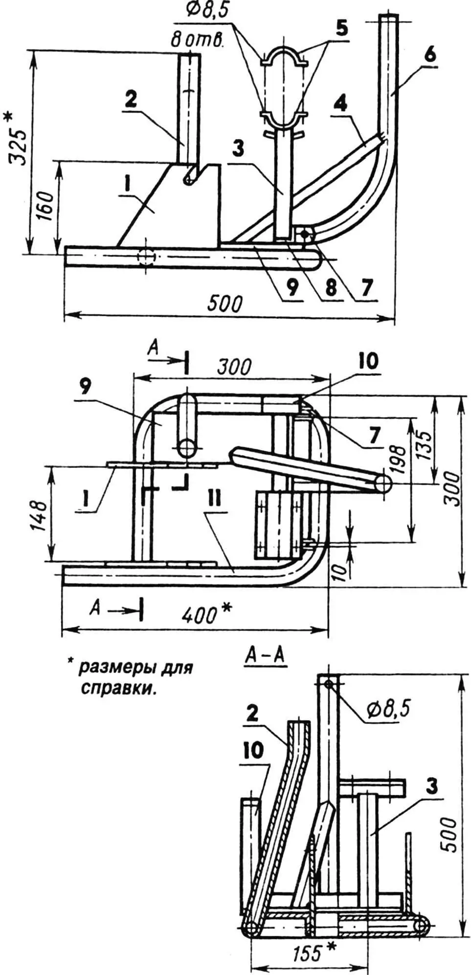
1 — drum support posts (sheet s5), 2 — exhaust support (pipe 32×2.5), 3 — main engine support (pipe 25x25x2.5, L150), 4 — boom brace (angle 25×25), 5 — half-clamps (sheet s5), 6 — lower boom section (pipe 26.8×2.5), 7 — anchor mounting brackets (sheet s3), 8 — beam (angle 30×30, L260), 9 — platform (channel 80x32x3), 10 — auxiliary engine support with cradle (pipe 25×2.5), 11 — frame base (pipe 32×2.5).
The block frame is structurally simple and easy to manufacture. Its base is bent from a pipe (it can also be welded from pipe segments), to which a channel-platform with one cut-off flange, drum posts, and exhaust support are attached. A transverse beam made of angle is welded to the platform, and to it, in turn, the main and auxiliary engine supports, the lower boom section, and anchor mounting brackets. Using the frame as an exhaust pipe and muffler significantly simplifies the layout of the power unit and also reduces the noise level.
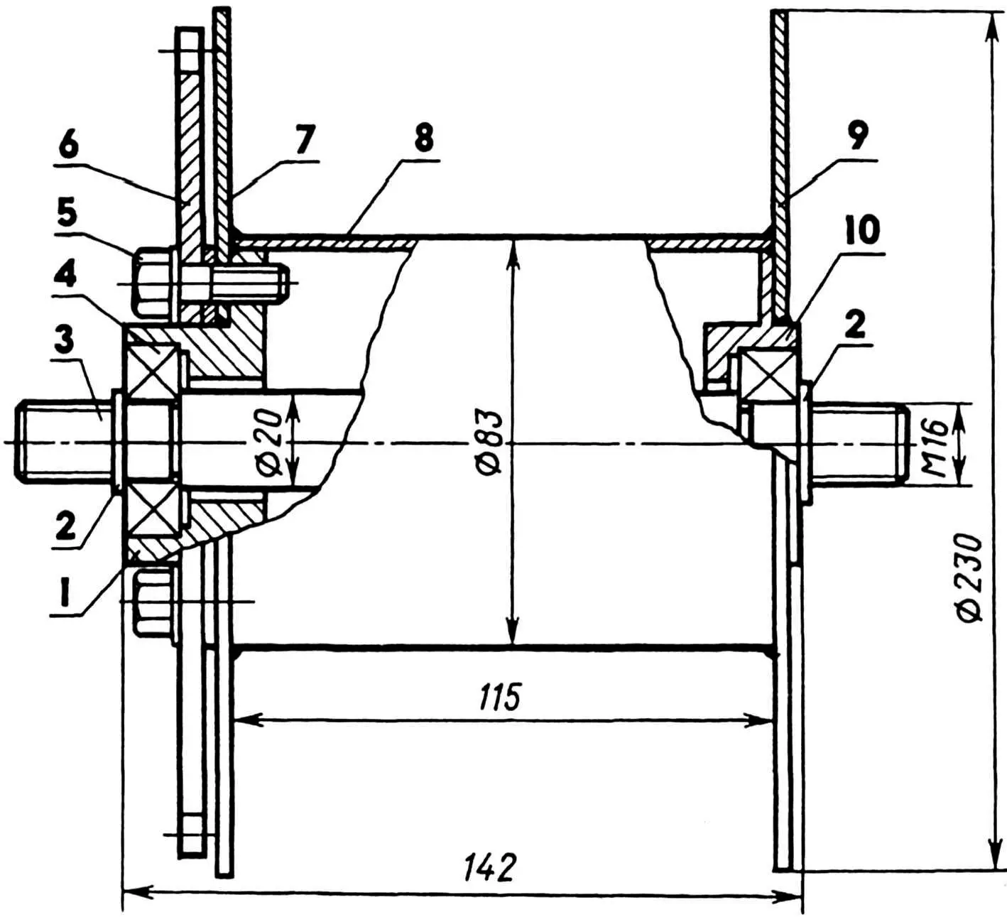
1,10 — bearing housings (St3), 2 — washers, 3 — shaft (steel 45), 4 — bearing 203 (2 pcs.), 5 — M8 bolt (4 pcs.), 6 — driven sprocket, 7, 9 — flanges (St3, sheet s2), 8 — drum housing (St3, pipe 83×2).
The winch drum rotates in bearings. It consists of two bearing housings welded together, two disk flanges, and a housing made from a pipe. Its drive from the engine is accomplished by chain transmission using standard motorcycle sprockets.
For plowing the soil, a plow is used, made in the style of a horse-drawn plow from a tractor plowshare and rigidly fixed with a post on a longitudinal beam. A fork is welded to the front part of the longitudinal beam, through which an axle with a connecting rod is passed. A field wheel is mounted on the axle, and a furrow wheel on the connecting rod. The plowing depth is adjusted by changing the angle of the connecting rod, and the parallelism of the furrows—by the position of the lock on the field bar welded to the fork. Such simple techniques significantly ease the plowman’s work, and he only needs to hold the plow vertically with handles hinged on the crossbar. The handle design allows the plow to be folded, for example, when transporting the unit in a passenger car, or for a person of any height to stand behind it.
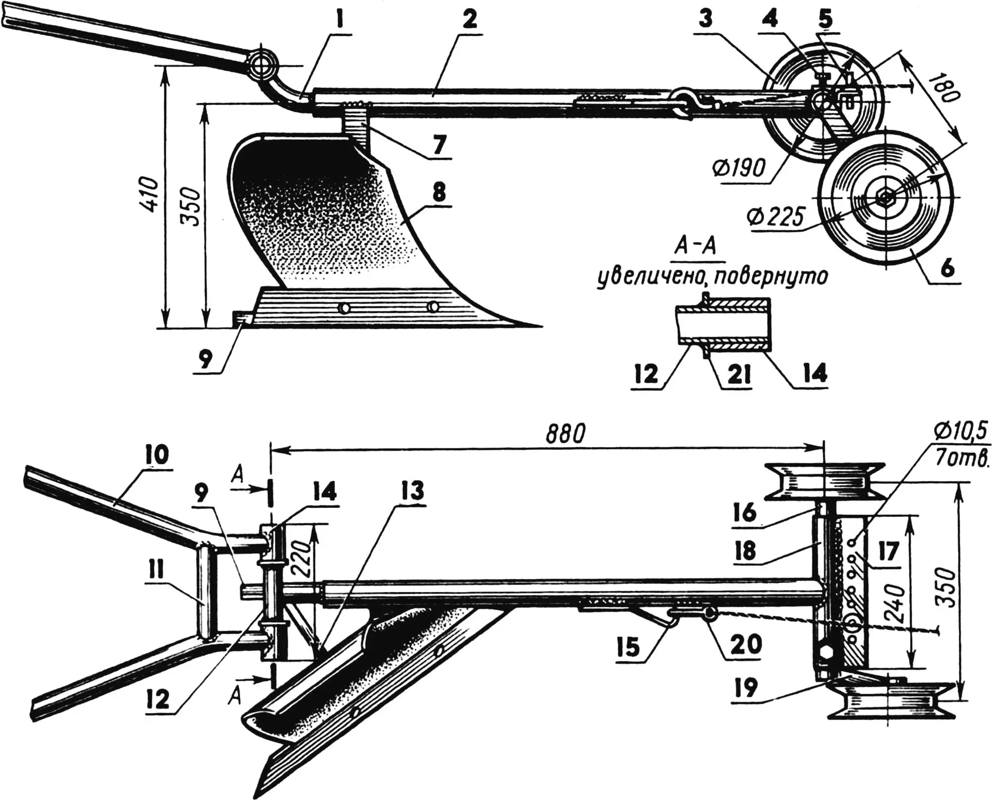
1 — lift (St3, pipe 33.5×2.8), 2 — longitudinal beam (St3, pipe 40×3, L800), 3 — field wheel (from combine belt tensioner), 4 — lock (M10 bolt), 5 — limiter, 6 — furrow wheel (from combine belt tensioner), 7 — post (St3, pipe 50×32), 8 — plow, 9 — slider (St3, angle 25×25), 10 — handle (St3, pipe 26.8×2.5), 11 — crosspiece (St3, pipe 26.8×2.5), 12 — crossbar (St3, pipe 26.8×2.5), 13 — brace (St3, angle 25×25), 14 — bushing (St3, pipe 33.5×2.8), 15 — hinge (St3, rod Ø12), 16 — axle (steel 20, rod Ø34), 17 — field bar (St3, angle 40×40), 18 — fork (St3, pipe 40×3), 19 — connecting rod (steel 20, pipe 32x25x2.5), 20 — traction cable hook, 21 — thrust ring (St3, sheet s3).
The process of plowing the soil using the “Krot” looks as follows. A power unit is installed on one edge of the plot being worked, which is secured in place with an anchor, and on the other—a plow, they are connected to each other by a cable. Each time after a working pass, the plow has to be moved back, that is, to make an idle pass. To avoid unwanted expenditure of effort and time, one block can be securely fixed on the opposite edge of the field and the cable connecting the unit and the tool, which are located nearby (on one side), can be passed through it—both passes become working.
V. KUDRIN
Recommend to read
 Overrunning Clutches Instead of a Differential
The need to have a nimble and reliable motorized assistant at my personal disposal I (like, probably, many others in a similar situation) felt with particular acuteness when I became the...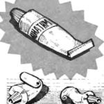 TSIATIM FROM THE TUBE
Do not rush to throw the used tube of toothpaste or shampoo. Carefully Unscrew the end of it, straighten it, and wash it with hot water. After drying, fill Ciation or other dense...
