It seems incredible that the chrome-plated roller bike, one of the numerous exhibits at the Central Exhibition NTTM-82, was made by teenagers — it has a very “factory-made” appearance. And yet it was made by members of the Tashkent City Station of Young Technicians Abdukhamid Dekhkambayev and Khasan Nurmatov. They were supervised by designer-constructor V. A. Ashkin.
Vladimir Alexandrovich developed a whole series of modifications of the teenage roller. He decided to build the most interesting of them with his young assistants. The first was the roller bike. The designer himself tells how it is arranged.
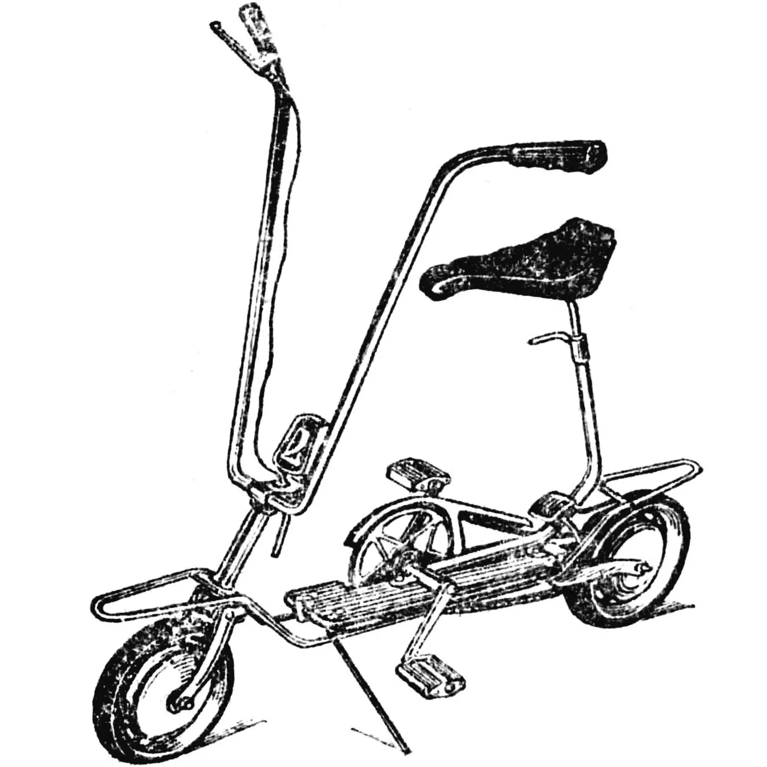
Our machine can serve both as a scooter and as a bicycle. Here’s how it’s arranged.
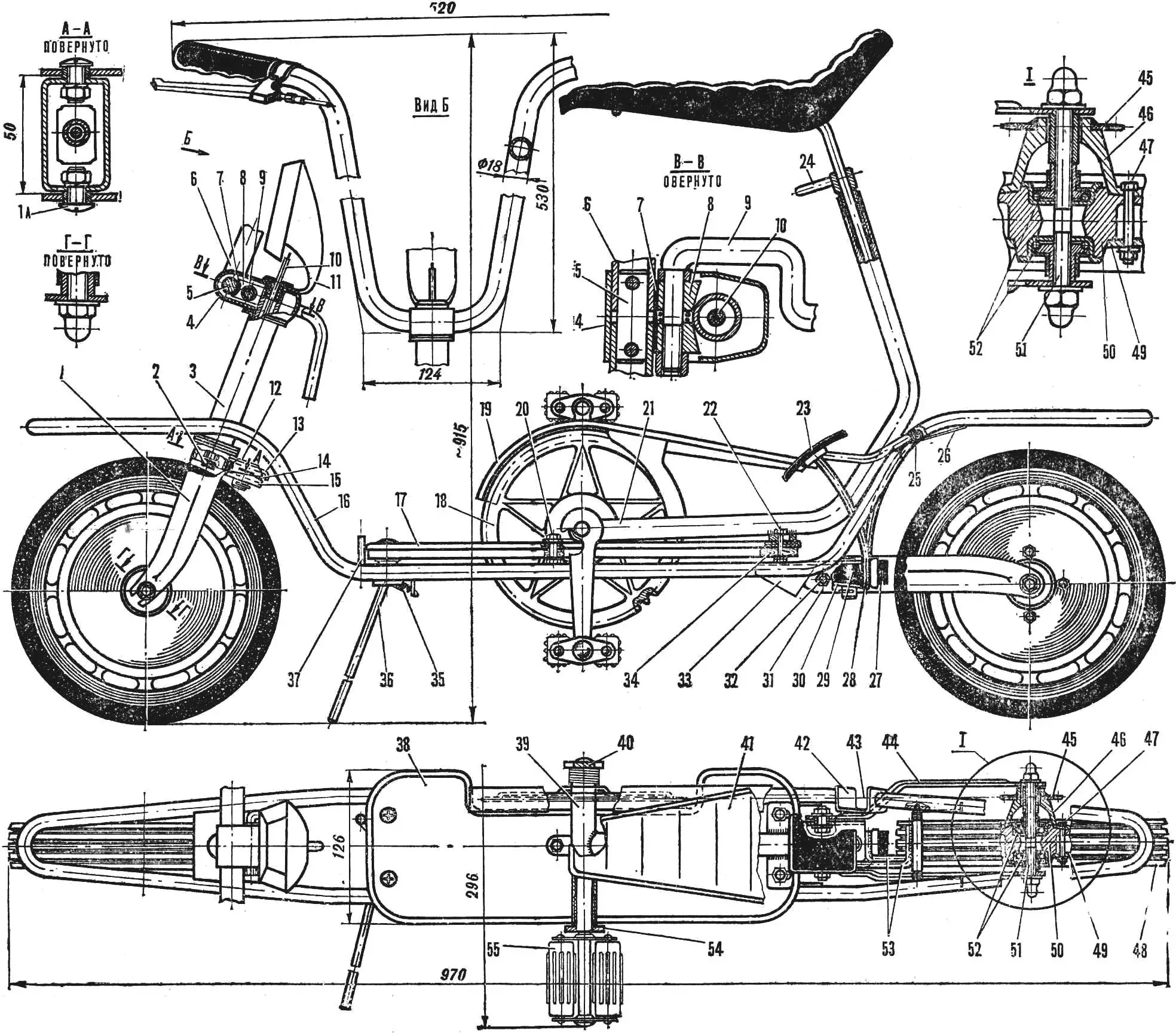
1 — front fork (1a — fork axle), 2 — hand brake pad, 3 — steering hub, 4 — fixing unit housing, 5 — connecting rod, 6 — handlebar, 7 — half-hub, 8 — wedge, 9 — fixator axle-lever, 10 — brake cable, 11 — emblem, 12 — shock absorber axle, 13 — fork protrusion, 14 — rubber shock absorber, 15 — handlebar axle protrusion, 16 — frame, 17 — support platform, 18 — drive sprocket, 19 — protective cover, 20 — front bicycle attachment mounting bolt, 21 — tubular arch, 22 — rear bicycle attachment mounting bolt, 23 — brake pedal, 24 — seat fixation lever, 25 — brake pedal axle, 26 — pedal spring, 27 — foot brake pad, 28 — brake force element, 29 — shock absorber, 30 — rear fork protrusion, 31 — fork, 32 — fork axle, 33 — fork mounting unit, 34 — support platform base, 35 — spring, 36 — folding support, 37 — folding support limiter, 38 — rubber mat, 39 — pedal axle, 40 — right pedal lever, 41 — seat, 42 — closing link, 43 — bicycle drive chain, 44 — right fork lever, 45 — driven sprocket, 46 — sprocket bracket, 47 — disk half connection bolt, 48 — tire, 49 — disk cover, 50 — disk, 51 — wheel axle, 52 — bearings, 53 — brake pedal force elements, 54 — left pedal lever, 55 — pedal.
The frame is bent from a steel tube Ø 12 mm, the ends of which are welded to the closing link (the bicycle drive chain passes through it). In three places, the steering hub, mounting units for the support platform and rear fork are welded to the frame.
Forks are cast from aluminum alloy and attached to the frame with hinges. To make the scooter ride smooth, they are equipped with shock absorbers: thick rubber washers are placed between the fork and bracket protrusions.
Wheels. By design, they are completely identical, only a driven sprocket is attached to the rear hub. The wheel disks are made of aluminum alloy, and each consists of two parts: a smaller cover and a larger one, cast together with the rim, on which a tubeless rubber tire is mounted.
The front fork axle is located in the steering hub welded to the frame and is crowned with an elegant handlebar and emblem.
Handlebar here is adjustable, it can be tilted forward or backward, or laid along the scooter if the latter is to be transported, for example, in a car trunk.
The design of the unit in which the handlebar is fixed in a given position is interesting. The handlebar, consisting of two halves connected by a rod with two pins, is located in the front part of the unit housing. A bronze friction half-hub is pressed against it, and steel wedges, through which the axle passes, are pressed against it in turn.
There is a spring between the wedges on the axle, but it, compressed, does not spread the wedges, since the right one rests against a washer, and the left one — against a nut. The axle ends with a lever brought out behind the emblem.
All these parts are not directly connected to the fork axle in any way; they are held in the unit housing by the force that arises when the lever is turned. Since the axle is its extension, it, screwing into a nut with coarse thread, brings the wedges closer together. Those, sliding along the fork axle, press on the friction half-hub and fix the handlebar in the desired position.
A hand brake lever for the front wheel is located on the handlebar. The rear wheel is also equipped with a brake, but a foot brake.
A support platform is located in the frame recess. It consists of a base cut from ten-millimeter plywood, a metal overlay and a rubber mat.
There is a folding parking support under the platform. It rotates on an axle in the support platform bracket, its extension is determined by a limiting rod.
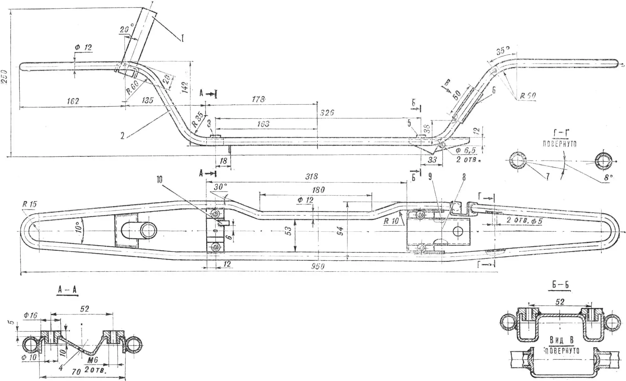
1 — steering hub, 2 — steel tube, 3 — front support platform mounting unit, 4 — hole for folding support axle, 5 — rear support platform and fork mounting unit, 6 — closing link, 7 — hole for brake pedal axle, 8 — shock absorber bracket, 9 — hole for fork axle, 10 — lug for folding support.
Now about how the scooter turns into a bicycle. There are three holes on the support platform into which bicycle attachment mounting bolts are inserted. The latter consists of a tubular arch, a seat and a bicycle drive.
The seat is connected to the arch with a telescopic clamp and is adjustable in height.
The bicycle drive, as on any bicycle, is pedals, a sprocket, a chain and a protective cover. Chain tension is achieved by moving the bicycle attachment forward: oblong holes in the mounting lugs allow this to be done.
And finally, the external design of the roller bike. The emblem, handlebar, steering hub, fixator axle-lever, frame, support platform trim, folding parking support and seat axle are chrome-plated. All other metal parts are painted silver. The seat is upholstered with leatherette.
Recommend to read
 “VALGA-COMBI” – CAR MADE OF PLYWOOD
Automotive design is a long-time passion of Krasnoyarsk resident Vladimir Aleksandrovich Gassan. Readers interested in homemade cars will probably remember both “ Mini-Valga ” and “... BOX COLLECTOR
My good friend since high school, enthusiastically collected stamps, matchbox labels, pocket calendars. Now his collection continues to children, and himself, he left only one passion:...
