Having a plot of land for a vegetable garden in our climate zone, regular watering is necessary to get a good harvest. But in the absence of your own water well or a well, at the established water rates, watering from the public water supply is quite expensive. After all, you have to water almost every day, for two, two and a half months, approximately one cubic meter of water per day. Having learned that household deep pumps consume approximately 0.5 kW (and this is the maximum) of electricity per cubic meter of water raised from a well, after doing simple calculations, compared to getting your own water, I came up with figures with quite significant savings.
And also, by applying various filters, including carbon ones, you can achieve quite good water quality for household purposes: for cooking and even for drinking without boiling.
And as a result, “the possibility arises” of installing a home (autonomous) water supply. I considered the most rational option to be independent well drilling with homemade installation (drilling could be ordered): after all, this way it’s not only cheaper, but also much more interesting.
I studied the relevant literature on this topic, settling on the simplest method (in my opinion) of cable percussion drilling. In some source it was described that using this method, even in ancient times, the Chinese drilled wells even in stone to a depth of 1.5 km, extracting salt. We didn’t need to drill to such a depth. I’ll remind you that drilling a well to a depth of more than 50 m requires a license from the appropriate organization and subsequent registration of the well.
Moving from simple to complex, I first decided to make part of the working tool: a spoon and a bailer (a tool for extracting soil from a well during drilling) and try to go at least a few meters without mechanisms.
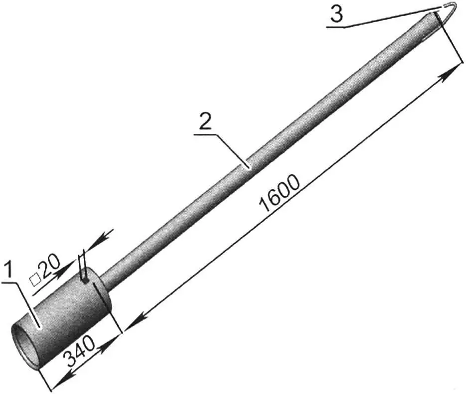
For drilling in wet soil, a spoon is necessary; this is the main working tool for passing through loam. The prototype of this tool was the Shitz spoon, only making a conical cup was not possible, so the part was made from an ordinary cylindrical pipe. In principle, such a cup design didn’t cause me any difficulties in drilling work, but it could be made even simpler. For example: take a pipe of smaller diameter (107 mm), fill it halfway with concrete – for weight, and use the second half as a cup.
My spoon consists of two parts: a cup (only the bottom is at the top) and a rod. The cup is made from a pipe with a diameter of 130 mm, its lower edge is sharpened (a chamfer is removed) on the inside. On the sides of the cup, in its upper part, there are two small symmetrical windows (holes) – for air to escape from the cup when it enters the ground. The second pipe – the rod – has a diameter of 58 mm, it is longer and its internal cavity is filled with concrete for weight. A bracket is welded to the upper end of the rod for attaching a rope to it through a carabiner (so it doesn’t twist). The spoon weighs 24.5 kg.
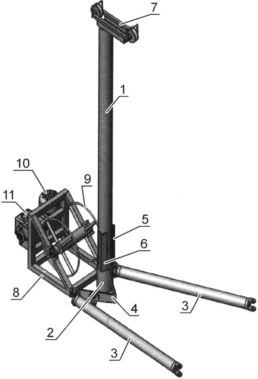
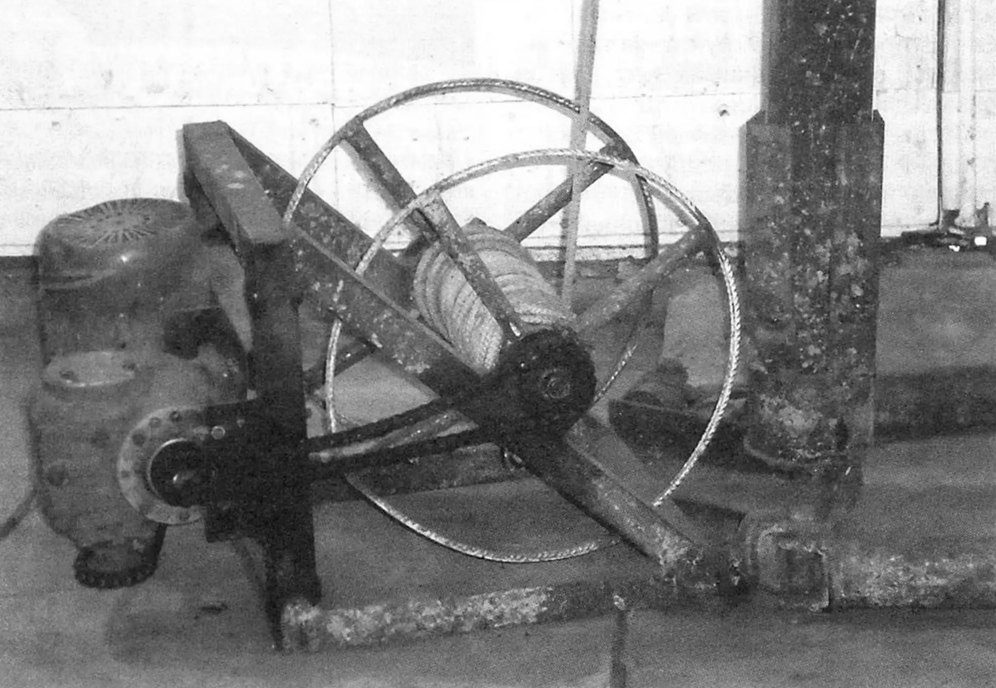
1 – mast; 2 – mast heel (pipe 130×10); 3 – leg (2 pcs.); 4 – triangular base (angle No. 7); 5 – support angles welded to the mast (3 pcs.); 6 – welded stop; 7 – pulley block (from agricultural machinery); 8 – drive frame (pipe 50×50); 9 – drum; 10 – electric motor; 11 – reducer
The technology of working with a spoon is simple. From a height of about two meters, we throw the spoon into wet soil. The spoon, cutting into the soil, deepens by several centimeters and when lifted, captures the soil wedged in it. On the surface, this soil is removed, and the cycle repeats again. For more convenient removal of soil from the spoon, I used a sapper shovel, having previously narrowed it by cutting approximately three centimeters from each side. The well diameter when working with such a spoon is about 200 mm, and this is excessive, since casing pipes are mainly used with a diameter of 100-110 mm.
But if you make a spoon from a pipe of smaller diameter, for example 107 mm, as suggested above, then the boom can also be made shorter, which is especially important when working in tight spaces.
1 – cup (pipe Ø130); 2 – rod (pipe Ø58); 3 – ear (wire Ø8)
Continuing to “scoop” soil and deepening, we reach such a wet area where the soil begins to “slip out” of the cup, since it is almost liquid there. Here it is necessary to use another tool – a bailer.
The bailer is made from the same 150 mm diameter pipe as the spoon. In its lower part, it has a two-flap inertial valve with a rubber seal for lifting water-liquefied soil.
1 – body (pipe Ø150); 2 – two-flap valve; 3 – ear (wire Ø8)
The body of the two-flap inertial valve has the same outer diameter as the bailer – 150 mm, only its wall thickness is 10 mm (later, so as not to look for a suitable pipe with thick walls or order a body from a turner, I simply inserted a ring made from a 7 mm diameter rod into the pipe, welded it and turned it with an angle grinder). The lower inner edge of the valve body (pipe) is sharpened (a chamfer is made) for better entry of the bailer into the soil. The flaps are cut from a steel sheet 4 mm thick. As a result, when dropping the bailer into the well, the flaps, falling into the liquefied soil mass, open, allowing the liquefied soil to pass through, and when starting to pull out the bailer, the valves close.
After lifting the bailer, the contents are poured out through its upper opening. The procedure is repeated until the well is cleaned, or a sump is developed. The weight of such a bailer with a valve was 17.3 kg, and without a valve – 11.3 kg.
1 – body (pipe Ø110); 2 – valve; 3 – ear (wire Ø8)
I made a second bailer of smaller diameter in order to compare productivity, as well as the difference in the volume of soil extracted from the well. And since inexpensive polyethylene pipe with an outer diameter of 107 mm is mainly used for well casing, and a larger diameter well is very rarely needed for household needs, much less soil will be extracted, so it is preferable to use this diameter – the volume of work will be significantly reduced.
As can be seen from the figure, the valve of the second bailer is simpler to manufacture due to the smaller diameter of the pipe used.
For passing through hard rock, I used a heavy crowbar. The slab is crushed with a crowbar and with the addition of water is “selected” with a bailer. However, I didn’t encounter such a layer, unfortunately (or rather, fortunately).
1 – housing (pipe Ø150×10); 2 – valve flap (steel, sheet s4, 2 pcs.); 3 – rubber gasket of the valve flap (rubber, s3, 2 pcs.); 4 – hinge (2 pcs.); 5 – hinge axis (2 pcs.); 6 – rivet (4 pcs.)
Having made such a simple device and purchased a long nylon rope (its length with a small margin can be determined by asking neighbors about the depth of their drilled wells), having installed a tripod with a pulley fixed at the top of this tripod, I tried to “drill” the soil. But due to the fact that the tool entered quite tightly, it was difficult to remove (tear away from the soil), and the drilling work became very heavy. Reducing the depth of tool entry into the soil by reducing the tool weight didn’t make sense, since the spoon penetration was optimal and was about five centimeters. Tearing the tool away from sticky soil each time and lifting it over and over again, you’ll get tired quite quickly.
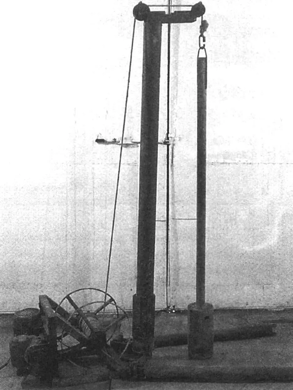
Then, to facilitate the work, it was decided to make a simple hoist from available materials. Having collected everything suitable that was available in the garage at that time, and having purchased the missing parts, I assembled the drilling rig itself.
1 – housing (pipe Ø110×10); 2 – valve (steel, sheet s4); 3 – rubber gasket of the valve flap (rubber, s3, 2 pcs.); 4 – hinge (2 pcs.); 5 – hinge axis (2 pcs.); 6 – rivet
With the drilling rig, the work went easier and more productively: the rig quite easily tears the spoon that has “cut into” the soil away from the main layer and lifts it to the surface. Having cleaned the spoon and lowered it again to the bottom of the well, taking hold of the rope, I lift it again approximately two meters and drop it.
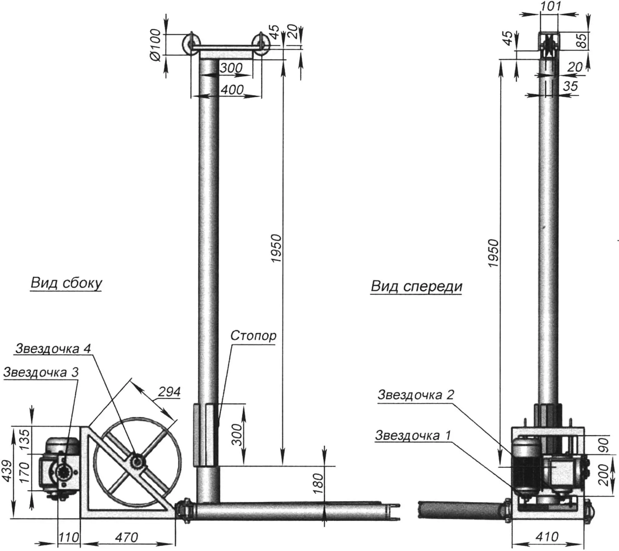
I welded the base frame of the drilling rig from 50x50mm square section pipes, and the triangular base for attaching the boom – from steel angle No. 7.
I made the boom from a steel water pipe with a diameter of 107 mm. With its lower part, it is inserted into a pipe with a wall thickness of 10 mm and having an internal diameter of 110 mm.
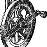
In the upper part of the boom, there is a block with pulleys (from a generator of some agricultural machine), having an outer diameter of 100 mm. I installed the pulleys without bearings for greater “freedom” – simply on a steel shaft with lubrication. I welded a limiting bracket to each pulley, made from a 9 mm diameter steel rod. This bracket prevents the rope from slipping off it.
For greater “stability” of the mast, I later had to weld three tightly fitting support angles No. 5 vertically during operation. It also turned out that the mast began to slowly rotate around its axis, and as a result, I welded a stop to the boom in the gap between the support angles.
As support legs, I used two driveshafts from a Moskvich-412 car. All crosspieces were previously removed from these shafts. One end of the shaft is attached to the frame, and the second is fixed in the ground. Namely, a pipe with an outer diameter of 27 mm is driven into the ground through the driveshaft yokes. The third fixation point is located on the base of the installation – this is a cut-off driveshaft yoke welded to the frame, all from the same Moskvich-412 car, through which a pipe is driven into the ground. The support legs have some degree of freedom in the horizontal plane: because the driveshaft yoke mounting was redesigned. Instead of a crosspiece, I used pins – I took cutoffs of the rear axle half-shafts from a Moskvich-412 car. Since I turned the half-shafts to a slight taper, they drive well into the driveshaft yoke eyes until there is no play. On the thicker side of this pin, I welded a washer for “greater” reliability, and on the thin side, I cut a groove in the half-shaft segment with an angle grinder. I inserted the UAZ car crosspiece retaining rings into this groove and laid washers, and thus fixed the pin in the crosspiece hole.
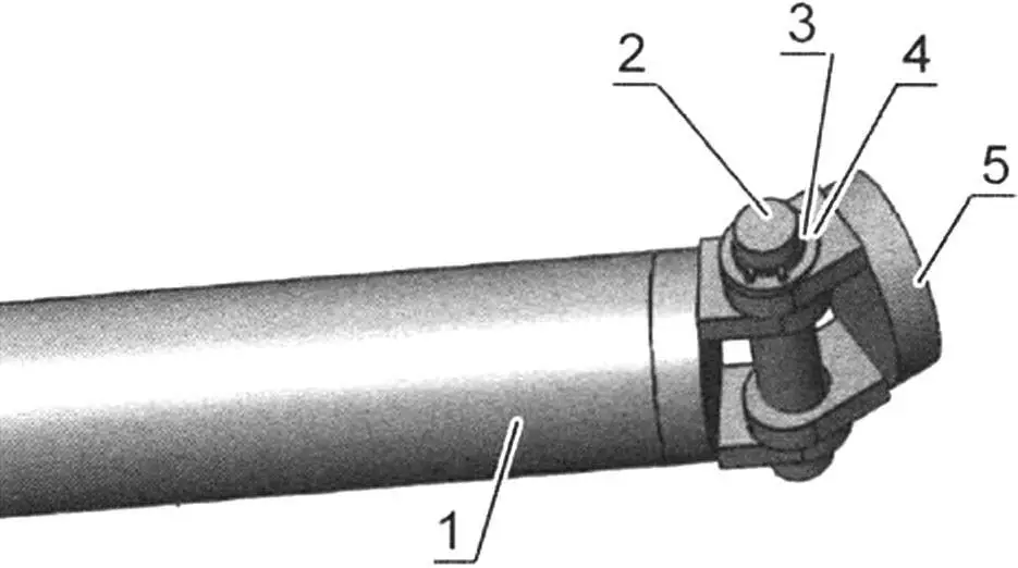
1 – leg (driveshaft from Moskvich-412 car); 2 – pin (part of half-shaft from Moskvich-412 car); 3 – retaining ring; 4 – washer; 5 – flange to be welded to the base
The rig’s winch consists of a worm gear reducer; a three-phase electric motor with a power of 2.2 kW, having 1000 rpm, and a rope reel.
I made the rope winding reel as follows: I welded a 78 mm diameter steel water pipe to a 30 mm diameter steel axle. To this pipe at the ends, I welded four spokes from a 15-inch steel water pipe on each side, to which, in turn, I welded a 10 mm diameter steel rod. The reel structure is balanced approximately (by eye), since the rotation speed is low and it is installed on two bearings at the ends of the axle. I used closed, ball bearings 30x63x15 mm, they are installed in homemade support housings. Namely: a steel strip 20 mm wide and 3-4 mm thick is taken, bent into a ring corresponding to the outer diameter of the bearing. Ears for a tie bolt are welded to the ends. This strip is then welded to a steel angle No. 3, in which two holes with a diameter of 10 – 11 mm are drilled for attaching the manufactured support housing to the frame.
Thus, the reel is attached to the frame. On the reel axle, to simplify the design, I didn’t use a cam clutch for dropping the tool, since I planned to use the rig as a cargo hoist in the future. And also because a rope was used, with which it was possible to work by hand. After finishing the work, the rope was removed and used for other work.
I used a worm reducer with a gear ratio of 1:40. It has the ability to lock the driven shaft when the driving shaft is not rotating, thereby preventing the rope reel from rotating.
The motor and reducer are connected to each other by a chain drive. A sprocket z1 = 11 teeth from a “Muravey” scooter is installed on the motor, and a sprocket z2 = 17 teeth with the same pitch is installed on the reducer, from a retired motorcycle. The second stage of the chain drive, transmitting rotation from the reducer shaft to the rope drum, consists of: a driving sprocket z3 = 11 teeth (all from the same scooter), installed on the reducer shaft; a driven sprocket z4 = 19 teeth installed on the rope drum shaft, all with the same pitch of 12.7 mm for a chain from a “Muravey” scooter. All sprockets, except z4, are welded to flanges and installed on shafts. Sprocket z4 is installed on a key directly on the reel shaft.
The drilling rig can be easily disassembled, moved, and installed in a room where drilling needs to be performed (for example, I drilled in my garage). And if you make the boom shorter, you can work in a lower room (in a basement or cellar).
Since the rig is not used often for its direct purpose in the household, it can also be adapted for other work, for example: use it as a hoist for loading-unloading building materials or when repairing equipment; lift or lower root crops to a cellar or basement. You can also use its individual units: the winch – for garden cultivation, having first removed the boom and legs; the rope – for household use.
Many builders, when erecting small houses and structures, use column foundations or place houses on piles: for their manufacture, drilling and pouring piles directly at the construction site is possible (vertical deviation with such drilling is minimal).
And even in disassembled form, the drilling rig together with the tool doesn’t take up much space in a garage or shed.
“Modelist-Konstruktor” No. 9’2016, D. SLONOV
Recommend to read
 MACHINE FROM HAND DRILL
Those who had to work with small parts, you know how hard it is to drill holes in them, the axes of which would be strictly perpendicular to the plane. The slightest imbalance leads to...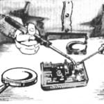 SOLDERING UNDER A MAGNIFYING GLASS
Anyone who ever worked Uborki or repair of electronic devices knows how the success of the quality and precision soldering. Great benefits this can bring the use of simple devices...
