Whatever amateur designers may attempt, no better running gear for snowmobiles has yet been invented than the repeatedly tested combination of “ski plus pneumatic tire.”
I became convinced of this after building and testing three variants of snowmobiles of my own design in sequence. The first machine had two skis in front and one wheel (a UAZ tire) in the rear. It was good in its own way, as it could easily enter any gate, tow small sleds, and follow the track left by a “Buran.”
The second machine already had two wheels in the rear, rigidly fixed on one axle. This gave it increased stability and the ability to carry heavier loads in sleds behind it.
And finally, the third machine: it’s on the same frame as the previous one, but with larger wheels, which sharply increases its cross-country capability.
I didn’t set out to have transformer snowmobiles. However, the last two modifications can be converted from one to the other at any time. It’s enough to replace the front bridge and the transverse steering rod (while the front supports with skis remain), and in the rear — the wheels and the driven sprocket. And also tighten the chain.
I want to tell you more about this third modification.
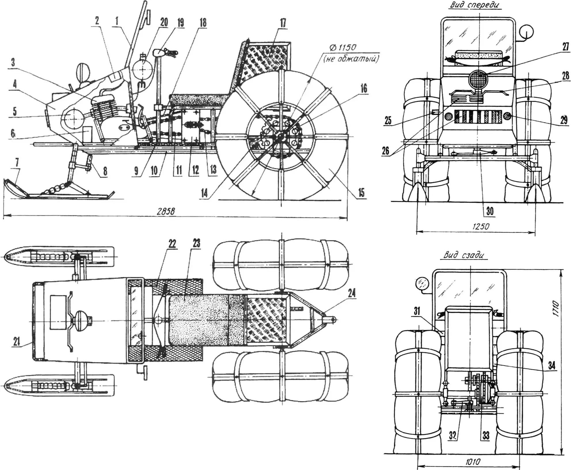
1 — windshield frame; 2 — relay-regulator; 3 — engine (from Izh-Yu-5 motorcycle); 4 — hood; 5 — muffler; 6 — battery; 7 — front support; 8 — transverse steering rod; 9 — steering shaft; 10 — frame; 11 — first stage transmission chain: 12 — intermediate reducer bracket; 13 — second stage transmission chain; 14 — chain tensioner; 15 — wheel; 16 — rear axle sprocket; 17 — luggage rack; 18 — chain housing; 19 — handlebar; 20 — fuel tank; 21 — bumper; 22 — footrest; 23 — driver’s seat; 24 — towing device; 25 — exhaust muffler pipe; 26 — ventilation grilles; 27 — headlight; 28 — hood handle; 29 — reflector; 30 — control rocker; 31 — instrument panel; 32 — handlebar arm; 33 — brake drum; 34 — fan housing.
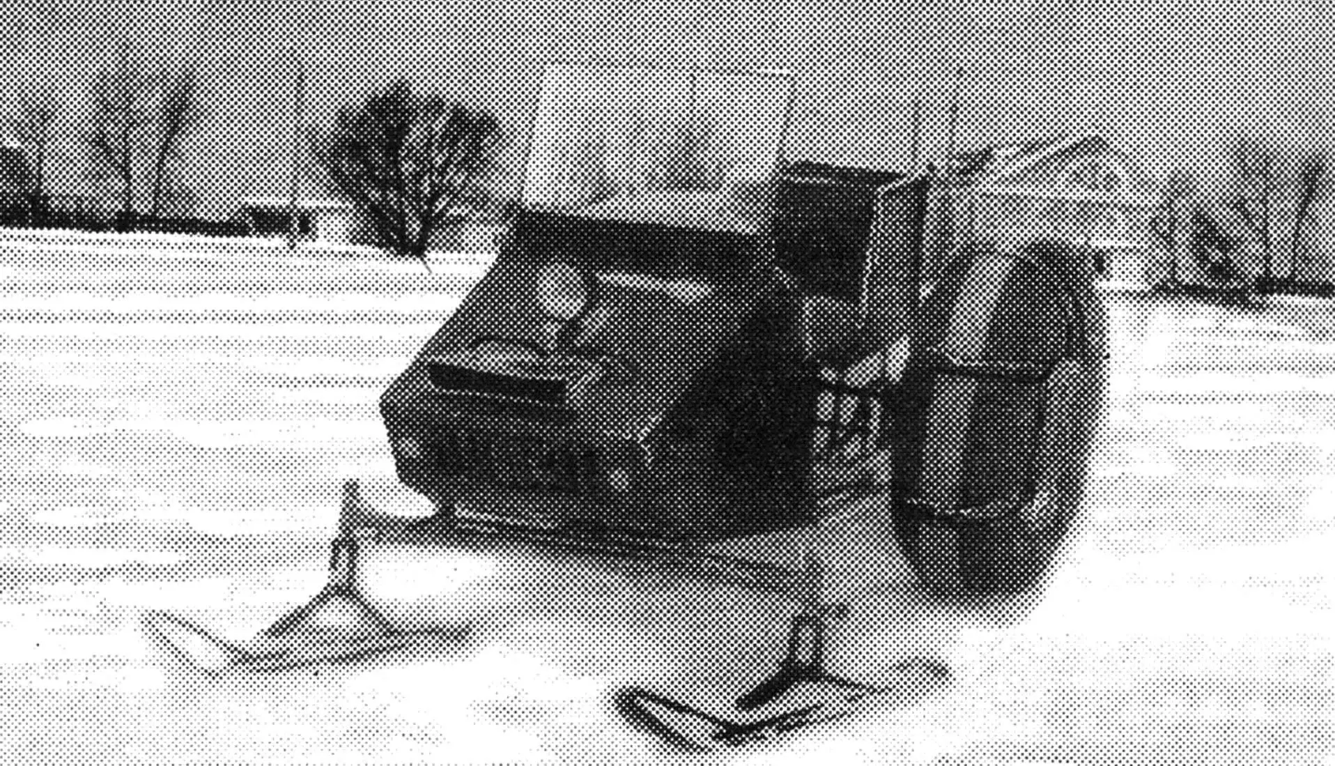
The snowmobile is open, single-seat, with front steering skis and rear drive wheels. The engine and most of the electrical equipment are located in front of the driver’s seat. Behind the seat is a fairly spacious luggage rack. I consider this layout advantageous. First, the axles are loaded evenly, and second, when riding, warm air from under the hood warms the driver.
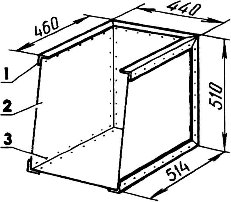
1 — frame (duralumin, angle 30x30x3); 2 — body panel (duralumin, sheet s2); 3 — rivet (duralumin, Ø3).
The snowmobile has no differential. This simplifies the design and improves snow performance. Speed on packed snow — up to 50 km/h. The machine can pull sleds with loads up to 200 kg behind it.
Now I’ll focus on the most important components and assemblies.
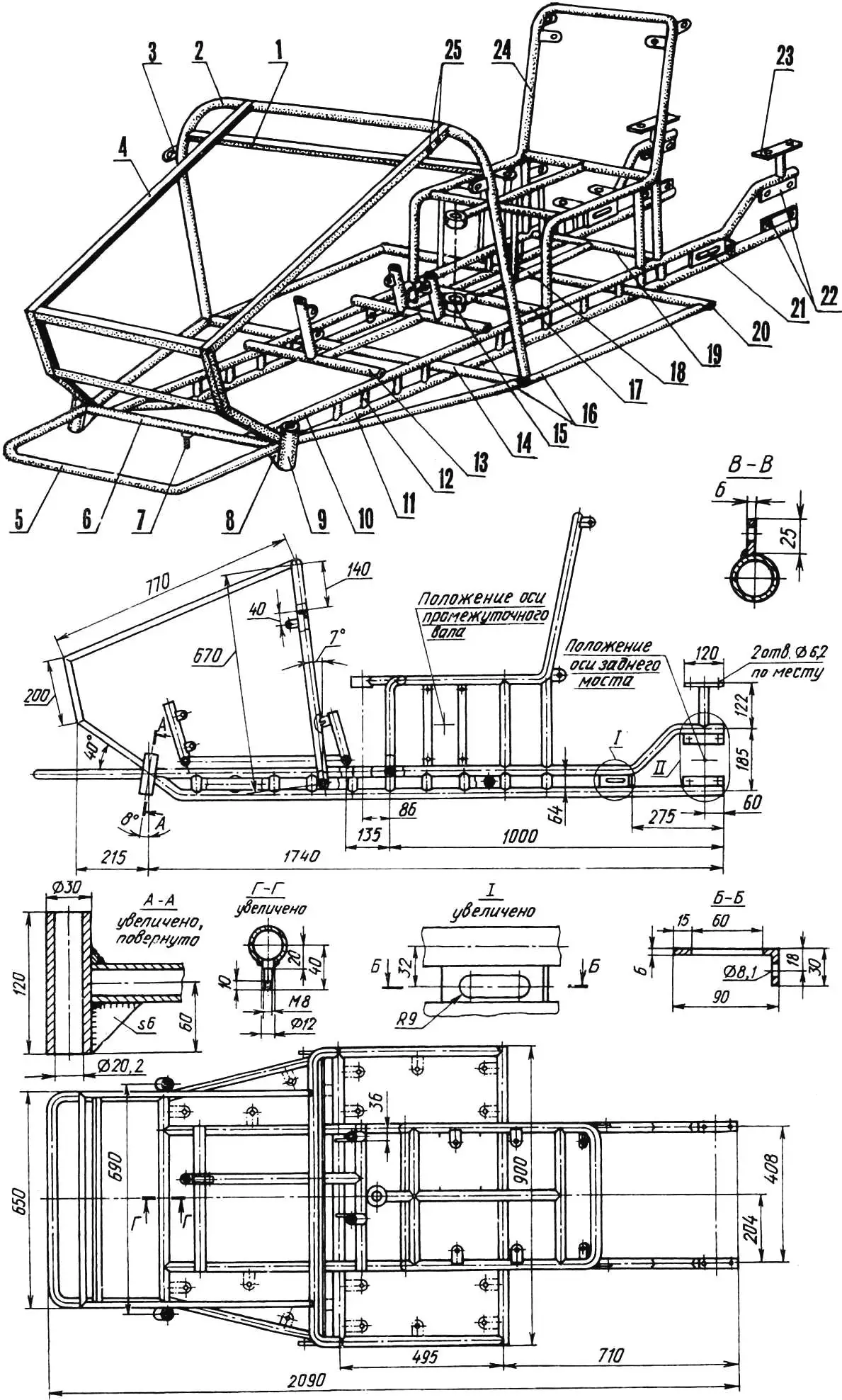
1 — fuel tank and instrument panel support (angle 20×20); 2 — hood arch (tube 26×2.5); 3 — hood mounting lug (strip 30×3, 2 pcs.); 4 — hood frame (angle 20×20); 5 — bumper (tube 32×2.8); 6 — front crossmember (tube 32×2.8); 7 — control rocker axis (screw M8); 8 — gusset (sheet s6, 2 pcs.); 9 — front axle mounting bushing (steel 20, 2 pcs.); 10 — upper longeron (tube 32×2.8, 2 pcs.); 11 — lower longeron (tube 32×2.8, 2 pcs.); 12 — crosspiece (tube 26×2.5, 20 pcs., arbitrary arrangement); 13 — engine frame; 14, 20 — floor supports (tube 32×2.8); 15 — steering shaft lower bearing housing (steel 20); 16 — floor limiters (tube 32×2.8, 2 pcs.); 17, 19 — middle and rear crossmembers (tube 32×2.8); 18 — longitudinal insert (tube 32×2.8); 21 — chain tensioner bracket (sheet s6, 2 pcs.); 22 — rear axle mounting strips (strip 25×6, 4 pcs.); 23 — luggage rack support (tube 26×2.5, strip 30×3, 2 pcs.); 24 — driver’s seat frame; 25 — holes for windshield frame mounting (4 pcs.).
The largest non-separable unit of the structure is the frame. It is made in parts, which are here named as the snowmobile frame, engine frame, and driver’s seat frame. I’ll describe them in that order.
FRAME of the snowmobile is assembled from water pipes. A hood frame made of steel angles is welded to it. For convenience of engine installation and removal, the frame can be removable (mine is exactly that). The engine hood itself, externally similar to the “Buran” one, is bent from an aluminum sheet and attached to the frame in four places with screws.
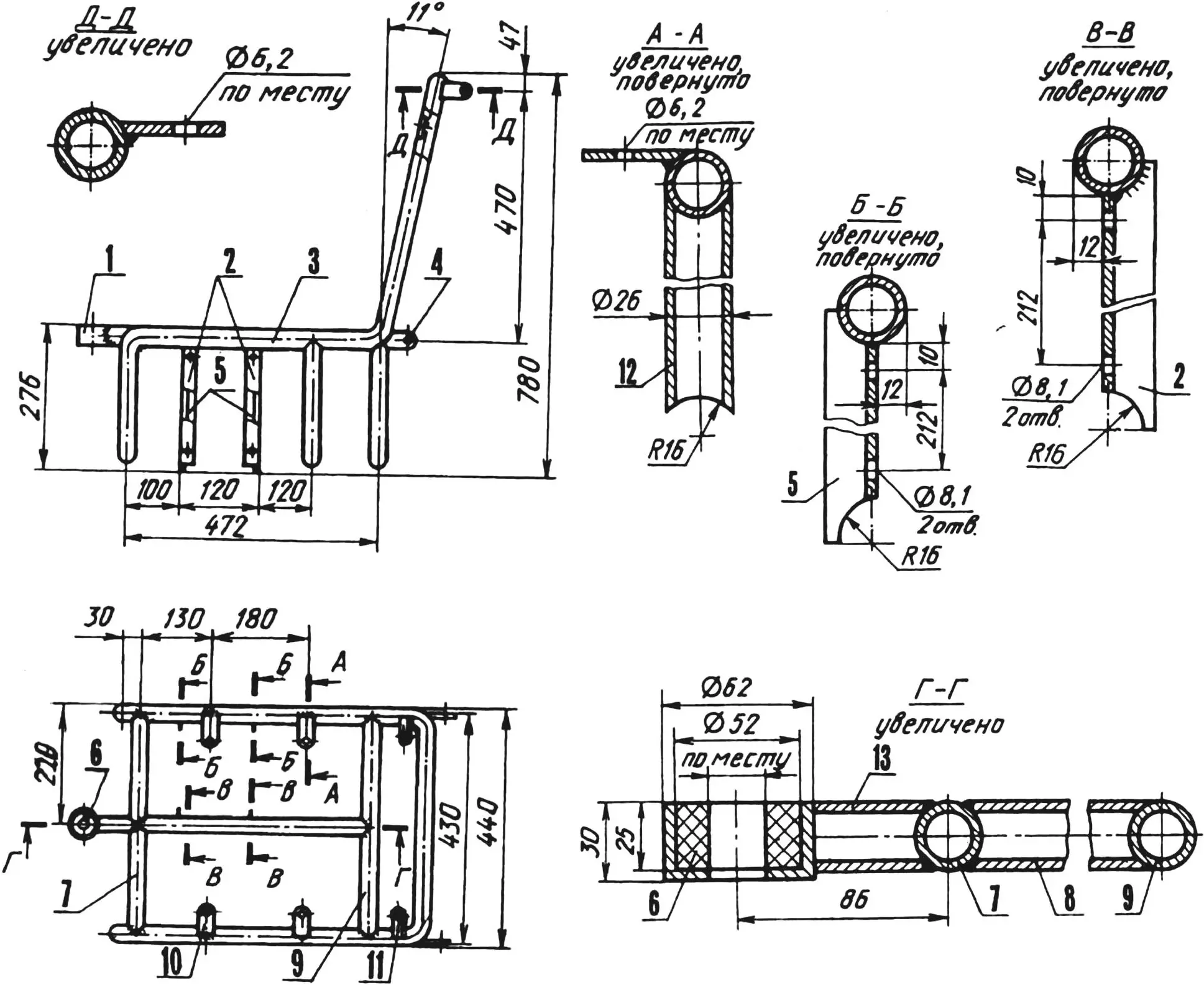
ENGINE FRAME is also made from water pipes. The dimensions given in the drawing and characterizing the mutual arrangement of lugs should be considered as approximate, since their adjustment is inevitable in accordance with the dimensions of the corresponding mounting units of a specific engine.
1 — holders (tube 32×2.8); 2, 5 — engine mounting lugs; 3 — crossbars (tube 32×2.8); 4 — traverse (tube 32×2.8).
The engine frame is attached to the snowmobile frame by electric welding with reinforcement of the welds with vertical gussets (not shown in the drawings).
DRIVER’S SEAT FRAME serves a triple purpose: in front, the upper steering shaft bearing housing is attached to it, on top — a seat with backrest, and below — an intermediate chain transmission reducer. The bearing housing is welded to the longitudinal insert of the frame; the seat and backrest (they have a wooden base) are screwed with screws to the corresponding hinges on the arch; the reducer is bolted to four vertical bracket-angles.
1 — steering shaft upper bearing housing (steel 20); 2,5 — intermediate reducer mounting brackets (angle 20×20, 2 pcs. each); 3 — arch (tube 26×2.5); 4 — luggage rack mounting hinge (strip 30×3, 4 pcs.); 6 — bearing bushing (rubber); 7,9 — crossmembers (tube 26×2.5); 8 — insert (tube 26×2.5); 10 — seat mounting hinge (strip 30×3, 4 pcs.); 11 — backrest mounting hinge (strip 30×3, 2 pcs.); 12 — support (tube 26×2.5, 4 pcs.); 13 — upper bearing bracket (tube 26×2.5).
ENGINE — motorcycle (from “Izh-Jupiter-5”) with forced air cooling. The fan is homemade, located on the engine on the right and driven by a rubber belt from a pulley on the generator armature. To install this pulley, the removable generator cover was drilled, and the bolt securing the armature to the flywheel was replaced with a longer one.
The engine starting system also underwent minor changes: the kickstarter was bent using a blowtorch so that when starting, there would be a full rotation of the crankshaft.
The snowmobile’s electrical equipment is motorcycle-type, with a battery. Designed for 12 V. The rectifier block is borrowed from an automobile generator. The relay-regulator R362B is also automotive.
TRANSMISSION of the snowmobile is a two-stage chain drive. The first stage chain (motorcycle) works between the engine and the intermediate reducer, and the second stage chain — between the reducer and the rear axle.
INTERMEDIATE REDUCER, as already mentioned, is located under the driver’s seat and is a simple structure consisting of a shaft and a block of motorcycle sprockets. The large sprocket (z=42) is taken from the rear wheel of a motorcycle. Its “native” hub was cut off and a new one welded on, into which a sealed bearing 203 is fitted on the right, and on the left — a hub with a small sprocket (z=16) and bearing 202.
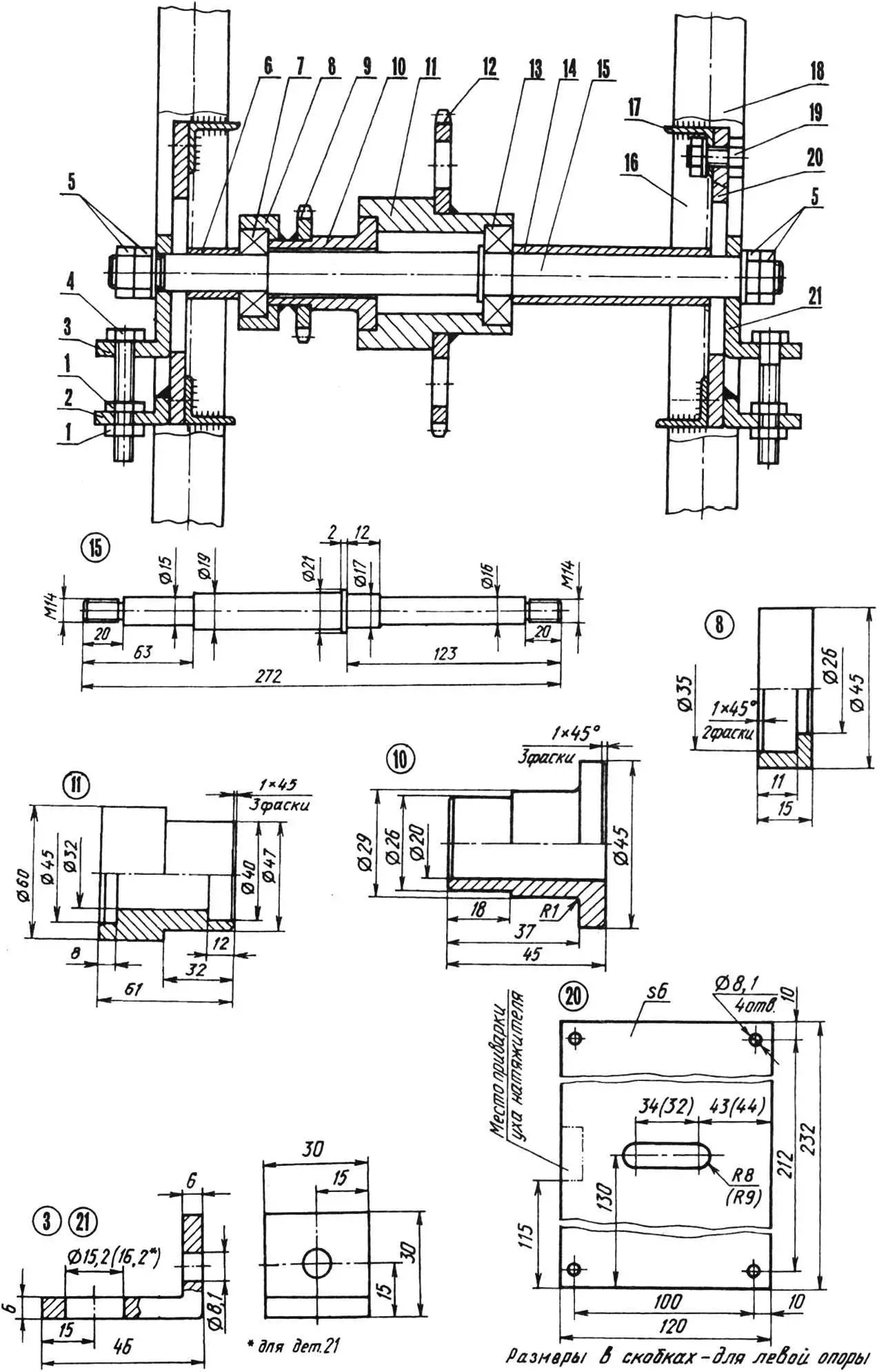
1 — M8 nuts (4 pcs.); 2 — fixed tensioner lug (steel 20, 2 pcs.); 3,21 — movable tensioner lugs (steel 20); 4 — tensioner M8 bolt (2 pcs.); 5 — M14 nuts; 6 — short spacer bushing (tube 20×15.2, L19); 7 — bearing 202; 8 — bearing 202 housing (steel 20); 9 — small sprocket (z=16); 10 — small sprocket hub (steel 20); 11 — large sprocket hub (steel 20); 12 — large sprocket (z=42); 13 — bearing 203; 14 — long spacer bushing (tube 23×17.2, L79); 15 — shaft (steel 20); 16 — snowmobile frame; 17 — reducer mounting bracket; 18 — seat frame; 19 — M8 bolt (8 pcs.); 20 — reducer support (steel 20, 2 pcs.).
The intermediate reducer shaft is located in slots of the supports and moves in them with the help of two tensioners. The exact position of the block on the shaft relative to the engine output sprocket is set by spacer bushings. If this position needs to be changed, one of the bushings must be shortened, and one or two washers added to the other.
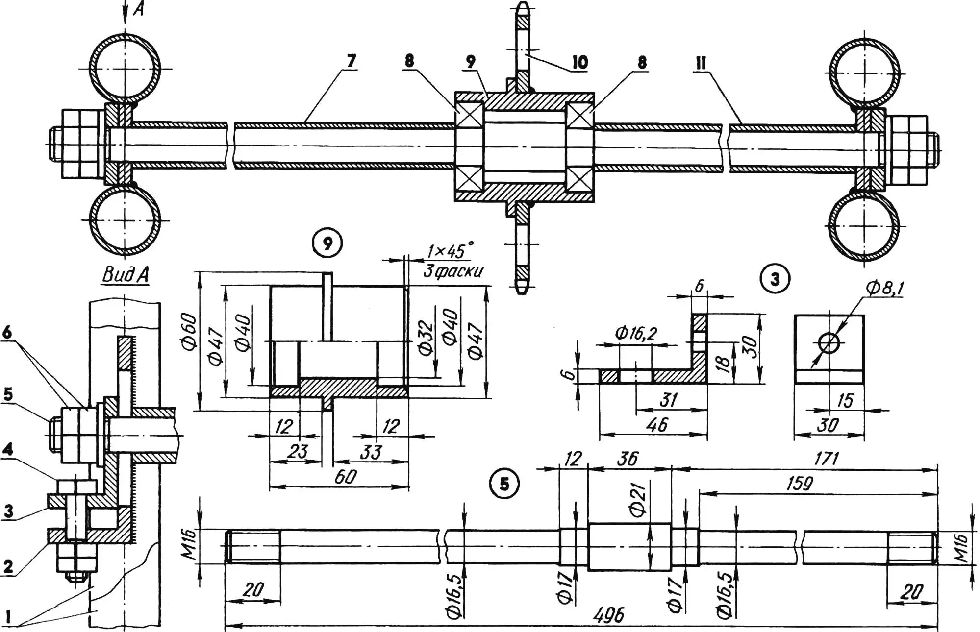
1 — frame longerons; 2 — tensioner bracket; 3 — movable lug (steel 20, 2 pcs.); 4 — M8 bolt (2 pcs.); 5 — shaft (steel 20); 6 — M16 nuts (4 pcs.); 7 — long spacer bushing (tube 23×2.8 L246); 8 — bearings 203; 9 — hub (steel 20); 10 — sprocket (z=42); 11 — short spacer bushing (tube 23×2.8, L128).
The second stage transmission chain is brought into working condition with the help of another tensioner located in front of the rear axle. The tensioner is a sprocket (z=42) on a hub with two bearings 203, which rotates on a shaft with spacer bushings. The shaft is located in slots of brackets welded to the frame.
REAR AXLE is made with a solid drive shaft. This simplified the design, improved cross-country capability, and had little effect on the snowmobile’s maneuverability — even with grippy bands, turning is performed normally. The shaft rotates in two bearings 207. Their housings, having leather seals, are welded to cheeks — plates made of sheet steel 6 mm thick, which have holes for mounting to the snowmobile frame. A disc with brake pads is screwed to the right housing with four M6 screws. The disc is cut from the housing of the driven sprocket of an “Izh” motorcycle. The brake drum is also motorcycle-type, only turned on a lathe on the outside (to a diameter of 240 and width of 50 mm) and on the inside (for another hub).
The rear wheel drive sprocket (z=60) is made on a lathe from a circle with a diameter of 350 and thickness of 10 mm. For this, the circle was turned on both sides to a thickness of 6 mm and marked with lines corresponding to the diameters of the pitch circle and the tip circle. (The calculation is not given here, as it is performed using known formulas.) Taking into account the chain pitch, centers were center-punched and 60 holes were drilled. The drill corresponded to the chain roller diameter. The resulting teeth were finished with a hacksaw blade and file.
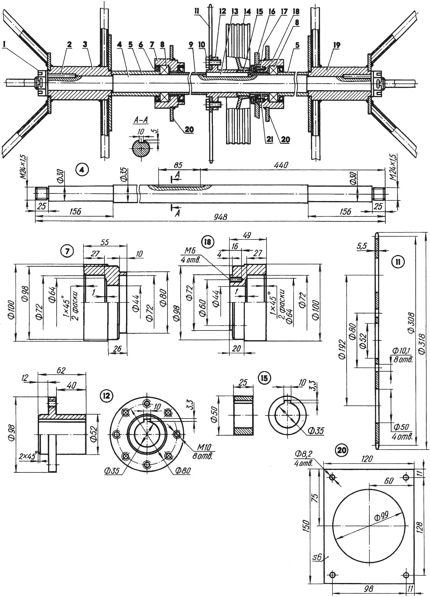
1 — M24x1.5 nut (2 pcs.); 2 — cylindrical key (St6, rod Ø6, L50, 2 pcs.); 3 — left wheel hub; 4 — shaft (steel 20); 5 — side spacer bushings (tube 45×4.5, L94); 6 — seal (leather, 3 pcs.); 7, 18 — bearing housings (steel 20); 8 — bearings 207; 9 — central spacer bushing (tube 43×3.5, L285); 10 — M10 screw (8 pcs.); 11 — sprocket (St5, z=60); 12 — sprocket hub (steel 20); 13 — prismatic key (St6, 10x8x85); 14 — brake drum (from Izh-Yu-5 motorcycle, turned); 15 — drum hub (steel 20); 16 — brake disc (from Izh-Yu-5 motorcycle driven sprocket housing); 17 — M6 screw (4 pcs.); 19 — right wheel hub; 20 — mounting cheeks (steel 20); 21 — distance bushing (tube 43×3.5, L36).
The sprocket is attached to its hub with eight M10x1 bolts. The hub on the shaft, like the brake drum, is fitted on a key. In addition, three more spacer bushings are fitted on the shaft.
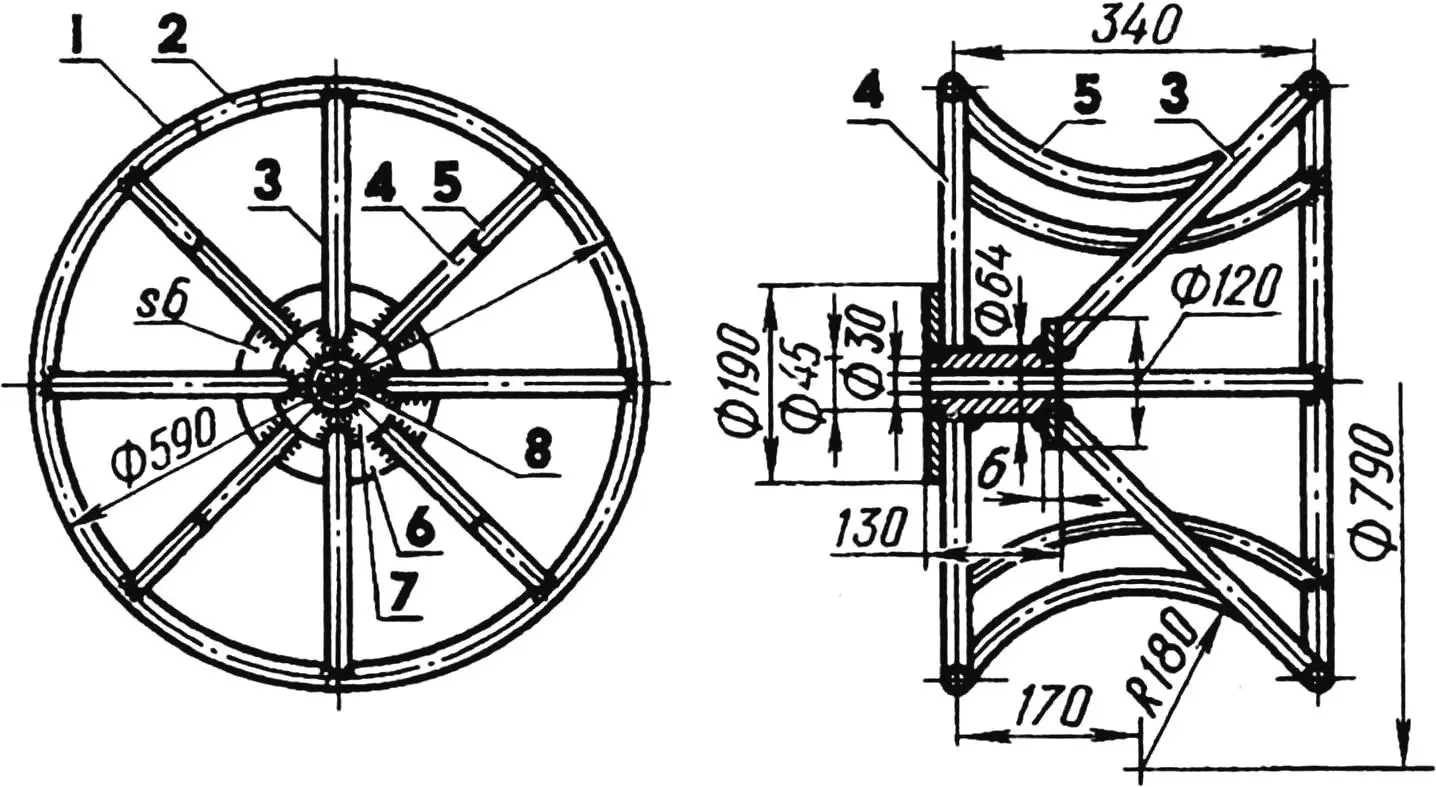
1,2 — rims (tube 20×2); 3 — inclined spoke (tube 20×2, 4 pcs.); 4 — straight spoke (tube 20×2, 8 pcs.); 5 — bed (tube 20×2, 8 pcs.); 6,7 — cheeks (sheet s6); 8 — hub (steel 20).
The spokes and rims of the wheel discs are welded from steel tubes. The disc design is quite clear from the drawing, so I won’t dwell on it. I’ll only focus on what’s not in the drawing. Eight M8 bolts are welded to each rim on the outside for mounting transverse bands — segments of conveyor belt 10 mm thick that pull the pneumatics to the rims. There are also longitudinal bands made from fire hose. The longitudinal and transverse bands are connected at their intersection points with special bolts. The ends of the bolts with nuts face outward and serve as ground- or, more accurately, snow-gripping lugs for the wheels.
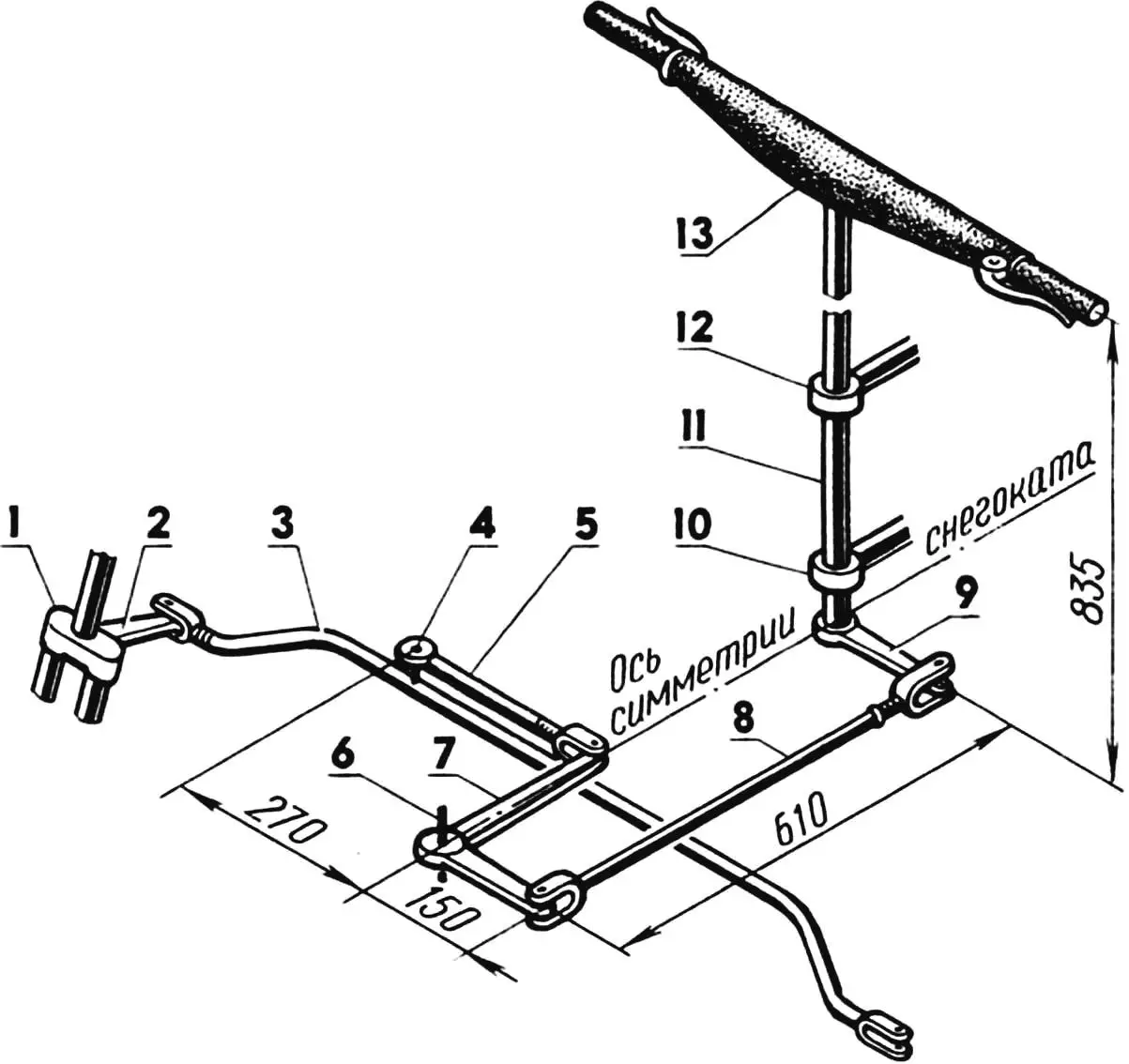
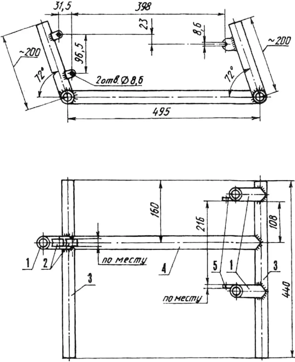
1 — right support fork (left fork conditionally not shown); 2 — fork arm; 3 — transverse steering rod; 4 — rod kingpin; 5 — link; 6 — frame kingpin; 7 — rocker; 8 — longitudinal steering rod; 9 — handlebar arm; 10,12 — steering shaft bearings; 11 — steering shaft; 13 — handlebar (from Electron motor scooter).
STEERING CONTROL. The steering shaft is a vertical steel tube 32 mm in diameter, rotating in two plain bearings with rubber bushings. A handlebar from an “Electron” motor scooter (with a “throttle” sector from a “Buran” snowmobile) is fitted on the upper end of the shaft, and a steering arm made from a bicycle pedal crank is welded to the lower end. A longitudinal steering rod going to the rocker on the snowmobile frame is attached to the arm. In turn, the rocker is connected by a link to the transverse steering rod of the front axle. The link and all rods here have tips with two degrees of freedom.
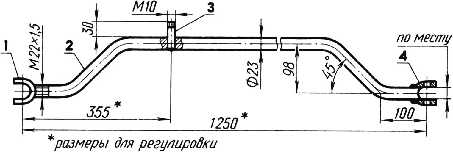
1 — adjustable fork (steel 20); 2 — rod (rod Ø23); 3 — kingpin (rod Ø10); 4 — non-adjustable fork (steel 20).
FRONT AXLE — easily removable, is a tube 42 mm in diameter with screws welded in the upper part for mounting to the snowmobile frame. Vertical sleeves reinforced with bands — strips of sheet steel 3 mm thick — are welded to the tube ends.
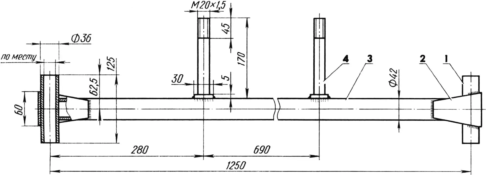
1 — sleeve (steel 20, 2 pcs.); 2 — band (strip 60×3, L220, 2 pcs.); 3 — beam (tube 42×5); 4 — mounting screw (2 pcs.).
Front forks borrowed from bicycles along with bearings are inserted into the sleeves. Steering arms (from bicycle pedal cranks) are welded to them at the rear, and at the bottom — joint bushings with homemade links and shock absorbers from a “Voskhod-2M” motorcycle attached to them.
SKIS of the snowmobile consist of steel frames and nylon bases, connected with rivets and tubes on the nose (for strength). The bases were obtained from a nylon tube with a wall thickness of 10 mm as follows: first, I cut blanks from the tube with an ordinary wood saw. To straighten them, I heated them along their entire length with a blowtorch, laid them between two thick boards, and pressed them with a weight. When the blanks cooled, I heated their noses again, bent them as needed, and cooled them with water. Skis with such a base have very good glide.
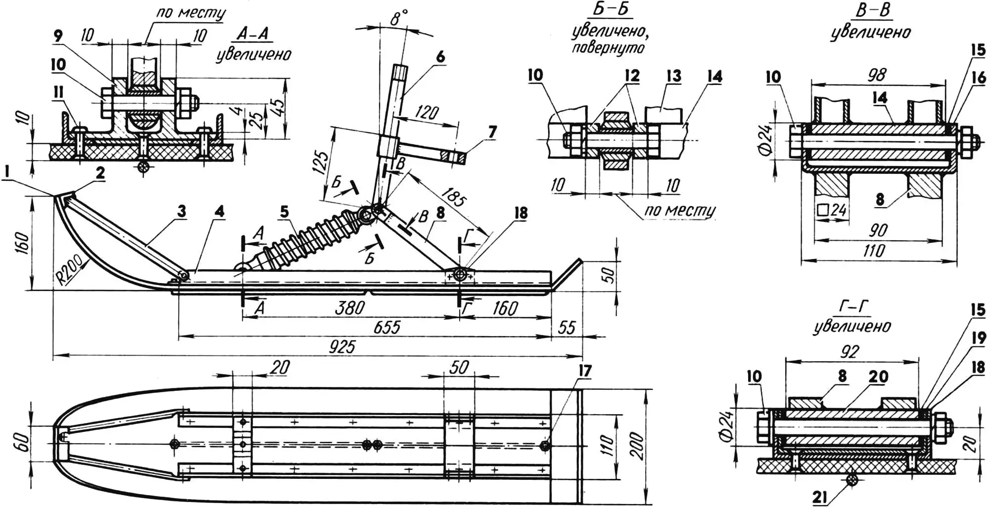
1 — ski base (nylon); 2 — crosspiece (angle 20x20x3); 3 — reinforcement (tube 15×1, 2 pcs.); 4 — frame (angle 20x20x3); 5 — shock absorber (from Voskhod-2M motorcycle); 6 — fork stem (bicycle front fork, cut); 7 — fork arm (bicycle pedal crank, cut); 8 — link legs (square 24); 9 — front bracket (steel 20); 10 — M12 bolt (4 pcs.); 11 — rivet (23 pcs.); 12 — shock absorber mounting lugs (steel 20); 13 — fork leg; 14 — joint bushing (steel 20); 15 — washers (brass, 4 pcs.); 16 — link collar (strip 24×4); 17 — M6 nut for edge mounting (4 pcs.); 18 — frame extensions (sheet s3); 19 — ski collar (strip 50×3); 20 — link bushing (steel 20); 21 — edge (rod Ø6, 2 pcs.).
The drawing shows that the skis have edges. Each consists of two rods 6 mm in diameter, screwed to the skis from below.
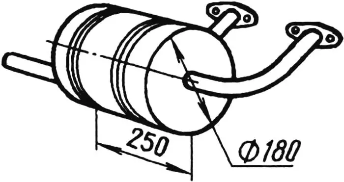
MUFFLER is welded from a steel sheet 1.5 mm thick. A mesh partition is inserted inside it to reduce exhaust noise.
BRAKE MECHANISM – foot-operated, with drive to the wheels. The pedal (it’s under the driver’s right foot) is borrowed from an “Electron” motor scooter. A two-arm rod made from a 7 mm diameter rod goes from it to the brake pads of the rear axle.
Of course, the design of my snowmobile is far from ideal. And I continue to improve it. I plan to install a reverse reducer instead of the intermediate transmission soon, and increase the width of the skis. And I also want to ride this machine in the summer, even though it has no differential. Of course, I’ll replace the skis with front wheels, and remove the ground-gripping lugs from the rear ones — for better maneuverability.
A. KLIMENKO
Recommend to read
 A SUBSTITUTE PIN
Carton steel doors or bars on the Windows to the concrete or brick walls specialists usually fastened with sharp pins. If you need to remove the box, the case is difficult to pull the... MICRO-BLERIOT
At the Moscow city competitions on indoor models in 1975, first place went to Evgeny Ermakov. His model is a copy of the "blériot XI" rubber engine showed in the three games great...
