The advantages of an outboard waterjet were already discussed in the article «Water instead of a propeller». Now we will tell you about its design. The waterjet installation we developed is intended for a wide range of enthusiasts. The waterjet is designed for a two-cylinder SM-557L engine, but can work with any other engine that develops similar power. So, in one of the latest versions, we used a power head from the «Vikhr» outboard boat motor, and the results were good. Engines of the scooter type or motorcycle engines can be used, provided they are equipped with a forced cooling system.
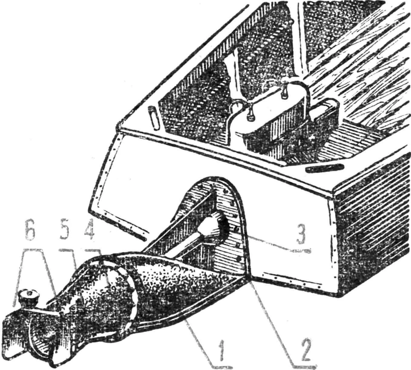
Fig. 1. General view of an outboard waterjet installed on a boat:
1 — water duct, 2 — flange, 3 — shaft line, 4 — nozzle, 5 — steering device suspension, 6 — steering plates.
The general view of the outboard waterjet device installed on a boat is shown in Figure 1. The propulsion unit consists of a cast aluminum water duct 1, made as one piece with flange 2 and shaft line 3. With the help of the flange, the entire system is attached to the transom of the vessel with through bolts through a rubber gasket that ensures watertightness of the connection. A removable nozzle 4 with a guide vane, also made of light alloy, is bolted to the stern flange of the water duct. The straightening vane is welded, with six blades made of 3 mm thick stainless steel. The water intake housing is shown in Figure 2.
Steering plates 6 are attached to the stern part of the nozzle using vertical hinges 5, which enable the vessel to turn. Reverse (reverse gear) is provided by shifting additional plates connected to each other by a breaking rod and installed on the same axis as the main steering plates.
The propeller shaft 3 (Fig. 3) is connected to the motor shaft through an elastic coupling 7 and has two support bearings: a rubber-metal bearing 9 — in the hub of the guide vane and a ball bearing — at the flange of the water intake.
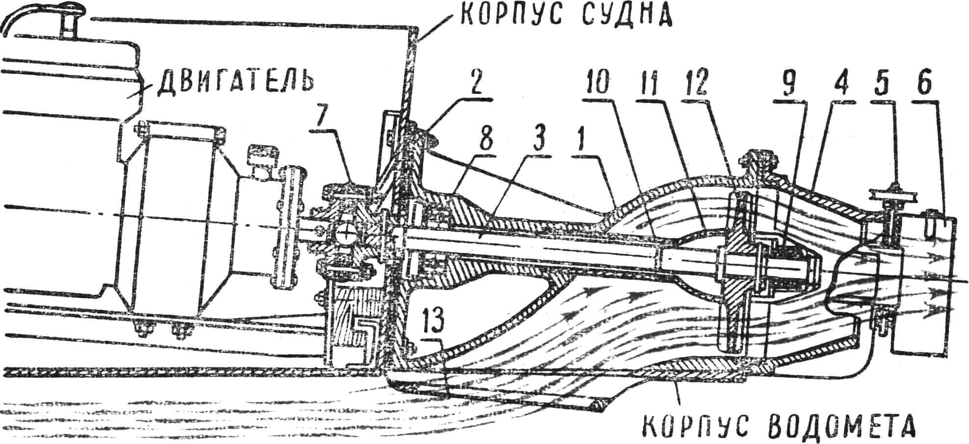
1 — water duct, 2 — flange, 3 — propeller shaft, 4 — nozzle, 5 — steering device suspension, 6 — steering plates, 7 — connecting elastic coupling, 8 — propeller shaft ball bearing, 9 — propeller shaft rubber-metal bearing, 10 — shaft protective housing, 11 — shaft fairing, 12 — impeller, 13 — water intake inlet.
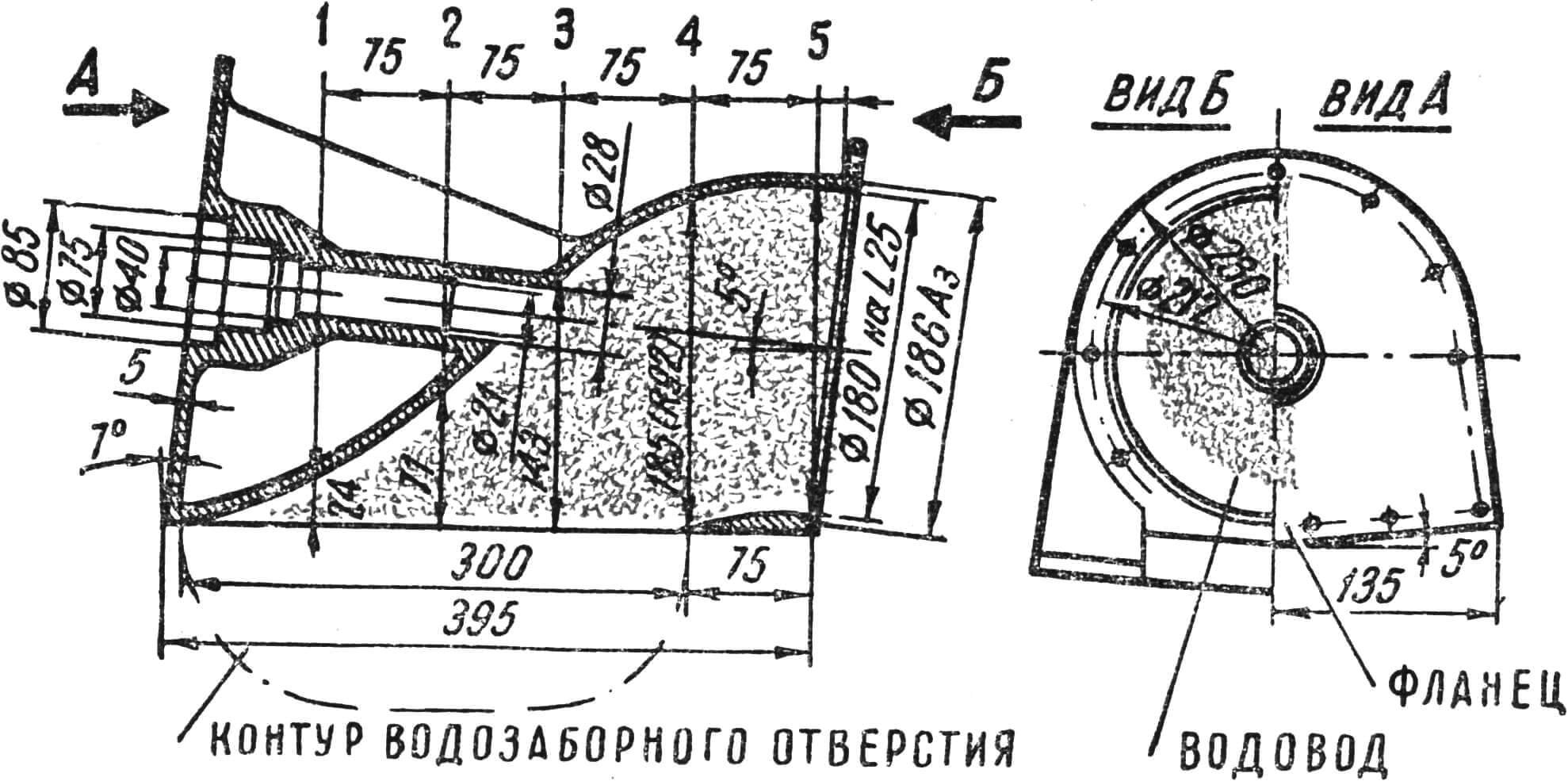
To protect against algae, the propeller shaft is covered with a light tubular housing 10, which turns into a fairing 11 on the rotor hub. The rotor 12 (four-blade impeller) has a diameter of 179 mm and a pitch of 130 mm. On the propeller shaft, it is secured with a cylindrical pin with a diameter of 6 mm, which ensures its safety (if the water duct becomes clogged, the pin is sheared). The water intake opening 13 is located immediately behind the transom edge of the vessel on which the waterjet is installed. To ensure reliable water intake, its rear edge is located slightly lower than the front one, thanks to which the waterjet can work even on hulls that have a «pickup» of stern lines.
Installation and dismantling of the waterjet are simple. The hole for the propeller shaft and most of the mounting bolts are located above the waterline. Therefore, after dismantling the installation, the hull does not need repair — it is enough to close the holes with sealed plugs.
In amateur conditions, the design we developed can be manufactured by welding from sheet steel. To do this, you will first have to cut flat parts according to the main projections (flanges, stiffening ribs), then turn the shaft line together with the ball bearing seat on a lathe and connect them into one piece, tacking in several places by welding (Fig. 4). The water duct should be made from two halves, with a split along the diametral plane. It is hammered out on a wooden block, after which the resulting blanks are fitted to each other and welded with a continuous tight seam. In this case, the chamfers on the parts must be filed so that the maximum cleanliness of the weld is ensured inside the water duct. The welded and cleaned water duct is carefully fitted to the flanges and stiffening ribs, after which it is welded in such a way that deformations are minimal. Slight warping is eliminated after welding by straightening.
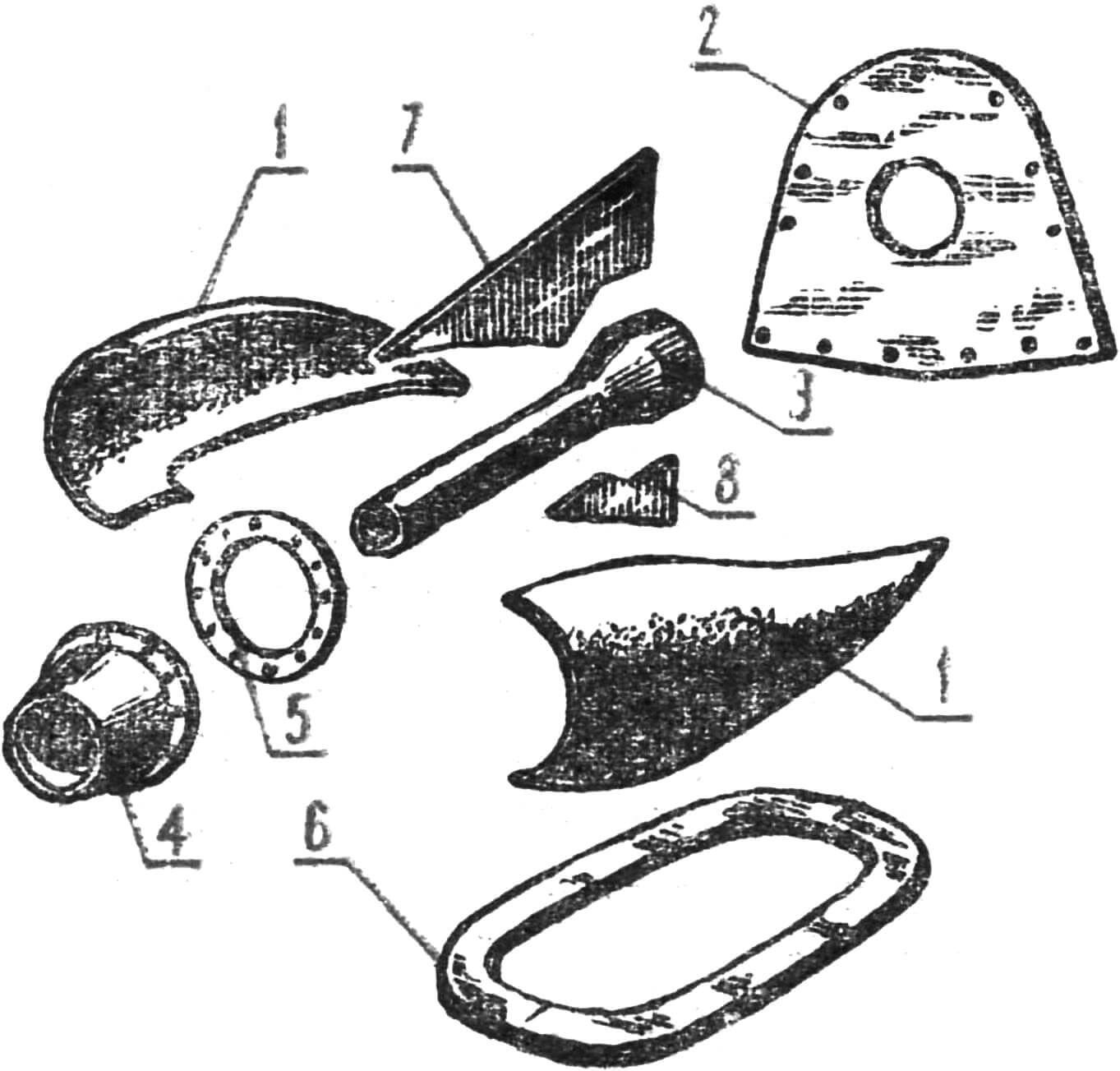
1 — water duct halves, hammered from 2 mm thick low-carbon steel, 2 — flange made of 5 mm thick steel, 3 — shaft line (turned part), 4 — nozzle (turned part), 5 — water duct flange, 6 — water intake lower flange, 7 and 8 — stiffening ribs.
During tests, our waterjet installation, mounted on a standard «Kazanka», showed the following results: thrust on moorings — 124 kg, speed with one person on board — 34 km/h, with four — 28 km/h. The motorboat was tested in a variety of conditions, including on very clogged water bodies, abounding in fallen trees, snags and reeds. Thanks to the protective housing and water intake grille, no clogging of the water duct was observed, the vessel freely overcame small shallows and «climbed» on the move over individual logs.
Thanks to the high traction characteristics of the outboard waterjet, the motorboat easily lifts a water skier weighing up to 90 kg and can tow him at sufficient speed.
On a planing vessel, the described waterjet installation is mounted along the lower edge of the transom and on the move touches the water only with its lower part. This provides the most favorable conditions for filling the water intake and at the same time does not create unnecessary resistance to movement. In the case of installing a waterjet on a displacement vessel, it must be mounted taking into account the latter’s draft. The lower plane of the water intake is located slightly below the operating waterline of the vessel, otherwise loss of power and reduction of thrust are inevitable.
The idea of creating an outboard waterjet turned out to be so obsessive that it was no longer possible to retreat and not think about it. One version was followed by others, failures were disappointing, but the goal was clearly outlined ahead. The result: after five years of work, we have before us an industrial prototype of an outboard waterjet, approved by the State Committee for Inventions and Discoveries under the Council of Ministers of the USSR (Fig. 5).
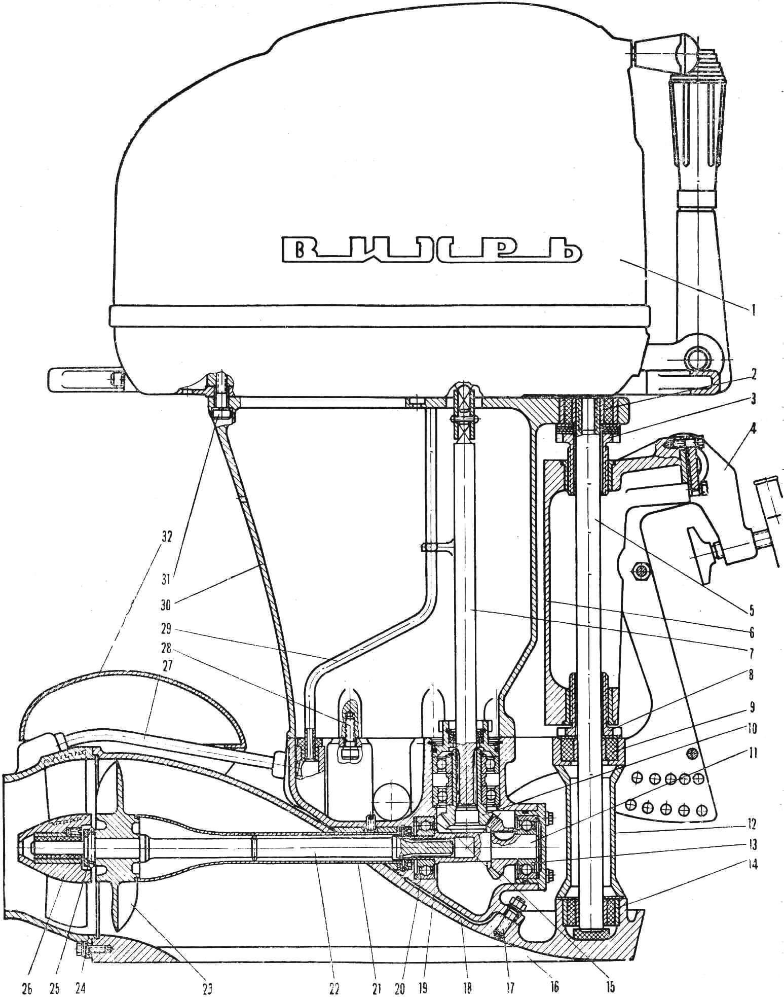
1 — power head (from «Vikhr» or «Neptun» outboard motor), 2 — lower unit suspension eye, 3 — waterjet depth adjustment device nut, 4 — motor mounting clamp to boat transom, 5 — swivel, 6 — suspension housing, 7 — engine vertical shaft (spring), 8 — nut, 9 — bushing, 10 — drive gear, 11 — driven gear, 12 — depth adjustment device housing, 13 — propeller shaft thrust ball bearing, 14 — swivel lower bearing, 15 — propeller shaft splined base, 16 — water intake opening, 17 — reducer housing to water duct housing mounting bolt, 18 — water duct housing, 19 — angular reducer housing, 20 — propeller shaft support bearing, 21 — propeller shaft housing, 22 — propeller shaft, 23 — impeller, 24 — waterjet nozzle, 25 — impeller mounting safety pin, 26 — propeller shaft rubber-metal bearing, 27 — tube supplying water from nozzle to cooling system, 28 — waterjet housing to lower unit housing mounting bolt, 29 — tube supplying water to engine jacket space, 30 — lower unit housing, 31 — lower unit to power head pan mounting bolt, 32 — reverse deflector.
Who hasn’t dreamed, while on a boat, of getting into the most secluded, remote places, crossing over snags and sharp stones without damaging the propeller? On an outboard waterjet, this is always possible. The immersion depth of the waterjet water intake is only 20 mm below the bottom of the boat. The controllability and maneuverability of the outboard waterjet turned out to be so effective that it amazed even the authors themselves, not to mention outside observers.
The outboard waterjet is not inferior in its characteristics to the best domestic outboard boat motors with propellers. It should be noted that it was the first in the practice of domestic and world shipbuilding to create a scheme for an outboard waterjet installation that ensures the operation of a boat practically without increasing the draft due to the propulsion unit.
Compared to outboard boat motors and foreign outboard waterjets, the minimum draft was achieved by using an axial single-stage waterjet propulsion unit, with torque transmission to the impeller through an angular reducer with a pair of bevel gears (Fig. 5).
The outboard waterjet consists of the following main units: an engine from the «Vikhr» or «Neptun» outboard boat motor 1, an angular reducer 10, a water intake 16, a pump part including the impeller 23 and the straightening vane, nozzle 24 and steering device 32.
Unlike conventional water intakes, the outboard waterjet water intake has two washers around the perimeter: lower and upper. The lower washer promotes flow formation at the water intake inlet and eliminates the possibility of air suction into the intake opening along the water intake housing. The upper washer is designed to reduce splash formation and washing of the hull by the water flow. This achieves a very noticeable reduction in water intake resistance.
The water intake housing has bosses for mounting the reducer using five M8 studs. The water intake can be cast together with the reducer housing. In amateur conditions, it is advisable to make it welded from 2—3 mm thick stainless steel.
The impeller blades are manufactured in accordance with Figure 5, finishing — using step squares on a special slipway.
The straightening vane can be made together with the nozzle housing or removable. In the first case, the blades are cast into the hub and nozzle housing; to increase the strength of the connection, the end edges of the straightening blades are made with a large number of teeth. For a removable straightening vane, the blades are attached to the hub and outer ring, which has a mounting diameter of 150 mm, by welding. A removable straightening vane is more convenient, as it allows for quick replacement or cleaning of the blades during operation.
Reverse of the outboard waterjet device is provided by a deflector hung on the nozzle. The rotation of the deflector, which changes the direction of the jet exiting the nozzle, is performed by hinged rods.
A feature of the outboard waterjet is the presence of a mechanism for adjusting the position of the propulsion unit (in height) relative to the bottom of the boat, which allows it to be used on boats with different transom heights without modifications.
By adjusting the position of the water intake opening plane in height, optimal operation of the waterjet propulsion unit can be achieved. The adjustment is made using two nuts screwed into the motor suspension swivel housing. The amount of movement is 25 mm, which allows the waterjet to be used on boats with a transom height from 380 to 405 mm. As test results showed, the most favorable results in terms of speed and thrust are obtained when the water intake nose is immersed 15—20 mm below the bottom of the boat.
Comparative speed characteristics of «Kazanka»-type boats with a «Vikhr» engine running on an outboard waterjet and the same motor but with a propeller are practically the same, and the speed reduction when the load increases occurs less intensively with the waterjet than with the propeller — due to flatter hydrodynamic characteristics. It is especially significant that due to the suction capacity of the water intake, the time for the boat with an outboard waterjet to reach planing is reduced; at the same time, maneuverability characteristics improve — turns, for example, can be performed even at maximum speed. In this case, the circulation diameter of a boat with an outboard waterjet is 1—1.5 hull lengths, that is, 3—4 times less than that of the same boat with a propeller version of the motor.
TECHNICAL SPECIFICATIONS OF «VIKHR» OUTBOARD WATERJET DEVICE
ENGINE engine type — two-stroke, two-cylinder, carburetor («Vikhr» or «Neptun»);
gear ratio from crankshaft to impeller — 0.95 (19/20)
WATERJET PROPULSION
impeller diameter in m — 0.143;
water intake diameter in m — 0.145;
impeller hub diameter in m — 0.053;
number of blades — 4 pcs., disc ratio — 0.9; impeller pitch in m — 0.130;
maximum impeller speed in rpm — 4850;
nozzle outlet cross-sectional area in m — 0.0115;
relative compression in m — 0, 788;
number of straightening vane blades — 5—6 pcs.;
straightening vane blade installation angle — 18°.
I. LAVROV, B. FAINERMAN
Recommend to read
 AND THROUGH THE SWAMP, AND SNOW
ATVs on tires of low pressure are becoming more comfortable. If ten years ago, enthusiasts of all-terrain vehicles created mainly of three-, four - and six-wheeled vehicle, devoid of... GLIDER FOR ALL: WHAT WILL IT BE?
Can you name at least one model class that is really available to everyone? Until recently the answer to this question could only be unequivocal: no. But the sport is evolving...
