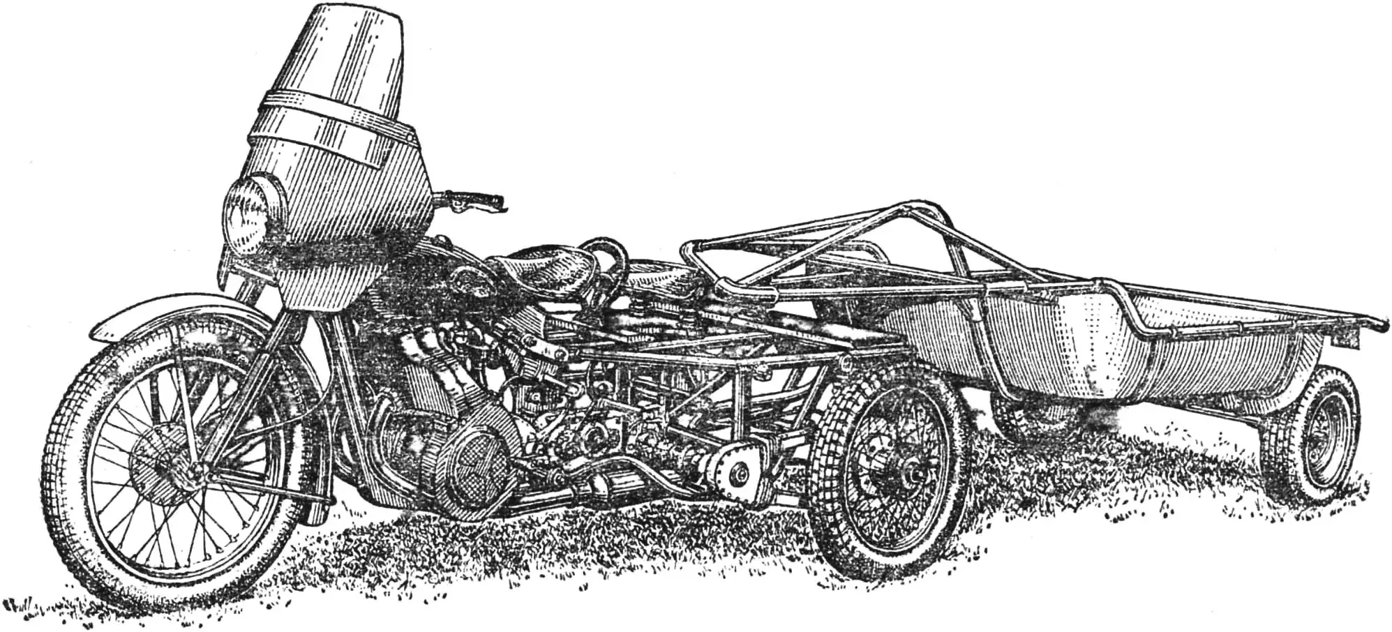
In recent years, with the growth of personal household farms, demand has increased for the Muravey cargo scooter; it is especially needed by rural residents. In 1983 alone, 12,000 of these machines will be sold. For the huge number of our villages, this is, of course, not much. By contrast, almost half a million motorcycles are expected to be sold this year. Perhaps here lies the reserve of missing cargo vehicles for homestead plots? Indeed, many amateur designers convert their machines into cargo tractors. D. I. Chernyshev from the town of Kasli in the Chelyabinsk region did the same. He turned his Izh motorcycle into a three‑wheel tractor with two driven rear wheels to use it in farm work and to haul vegetables and potatoes from the garden on a small semi‑trailer.
Any amateur designer is first of all interested in how much work is ahead and which parts and assemblies will have to be made from scratch so that, as they say, the machine will run. So I will list them right away: I assembled or manufactured the following main units — a reducer with differential in a single housing, the power drive to the rear wheels and the housings of their suspension, the sub‑frame, and the brake mechanism. At the same time, I used several parts from an S3B microcar: I took its engine cooling system, differential, cardan joints, springs, and friction dampers of the rear suspension.
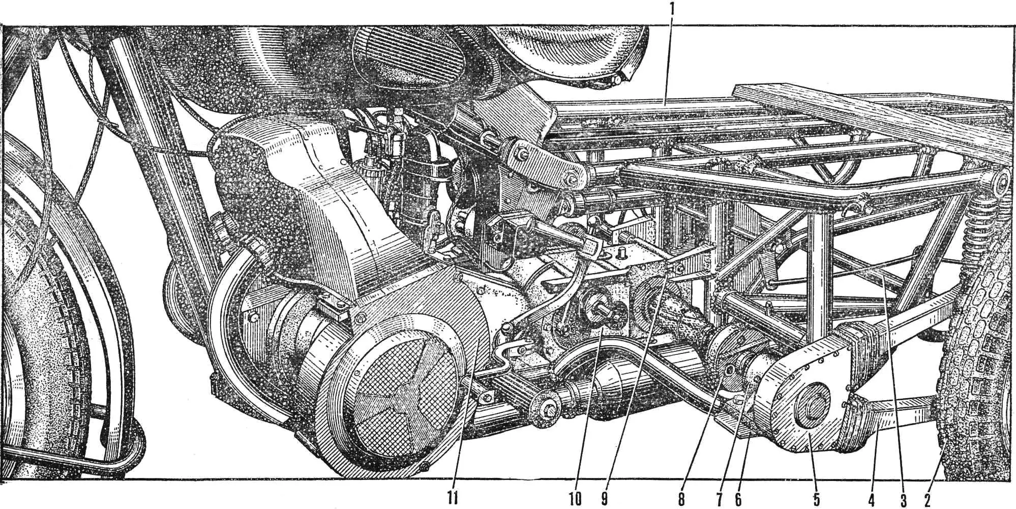
1 – frame, 2 – rear wheel, 3 – rear‑wheel axle, 4 – chain guard, 5 – drive sprocket housing, 6 – gusset plate of the support, 7 – support of the intermediate shaft, 8 – cardan shaft coupling, 9 – eye for mounting the reducer, 10 – “reducer–differential” block, 11 – motorcycle engine.
I would call the finished machine a mini power tractor, because its wheelbase is only 1850 mm, the track is 1100 mm, and its base is an Izh motorcycle. After the conversion, a three‑wheel layout was obtained, similar in scheme to the Muravey cargo scooter.
The engine remained stock, but I added forced cooling: I removed the left crankcase cover and replaced it with an S3B fan and shroud.
Power is transmitted from the engine to the rear wheels through the “reducer–differential” block.
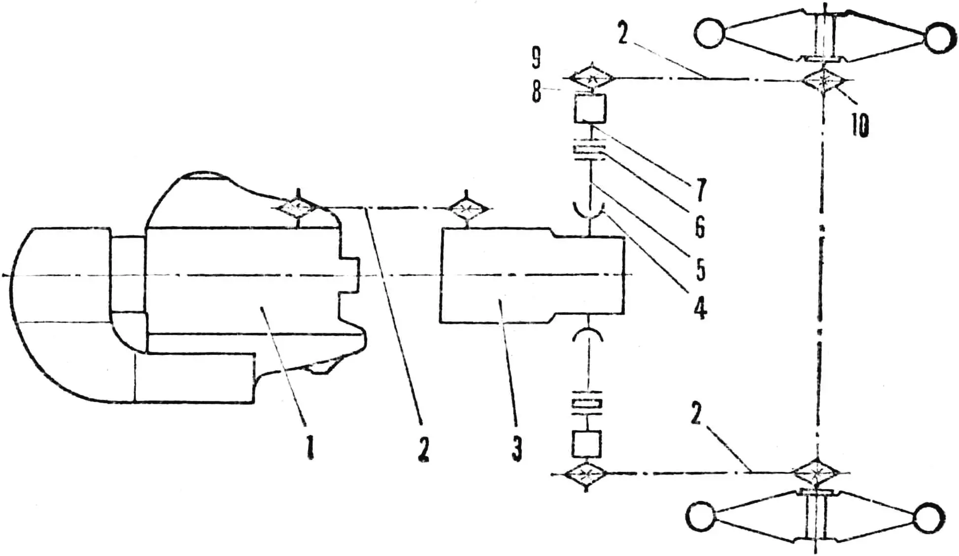
1 – engine, 2 – roller chain, 3 – “reducer–differential” block, 4 – cardan joint of the output shaft, 5 – cardan shaft, 6 – coupling, 7 – intermediate support, 8 – intermediate shaft, 9 – drive sprocket, 10 – driven sprocket of the rear wheel.
The new housing for the block was cast from duralumin by simple sand casting. In making the reducer, I used several gears and shafts from the Izh gearbox with its shifting mechanism, as well as the differential from the microcar. There are three working gears: two forward (two‑stage) and one reverse (single‑stage). Gear ratios are 1.14 for the higher road gear, 2.55 for the lower working gear, and 2.41 for reverse. Tractive effort from the engine is transmitted by a roller chain directly to the secondary shaft of the reducer: the first‑gear pinion has been removed from the intermediate shaft. For the chain drive, two 18‑tooth sprockets from the gearbox secondary shaft are used, giving a ratio of 1:1. Tractive effort from the reducer to the rear wheels is transmitted from the output shafts of the differential (with cardan joints from the S3B) through cardan shafts, couplings, intermediate‑shaft supports with their drive sprockets (also 18‑tooth), and roller chains. For safe operation and protection from dirt, the chains are enclosed in guards. The sprockets are also covered with housings and rubber boots. The bearings of the intermediate supports are mounted in special housings.
The shafts are keyed to their hubs. The rear wheels have standard driven sprockets with brake drums: the gear ratio between drive and driven sprockets is 2.33. All roller chains are also standard P‑4. The couplings are finger‑type, from an M‑72 motorcycle. To adjust chain tension, the design allows limited movement of the reducer block and the intermediate supports.
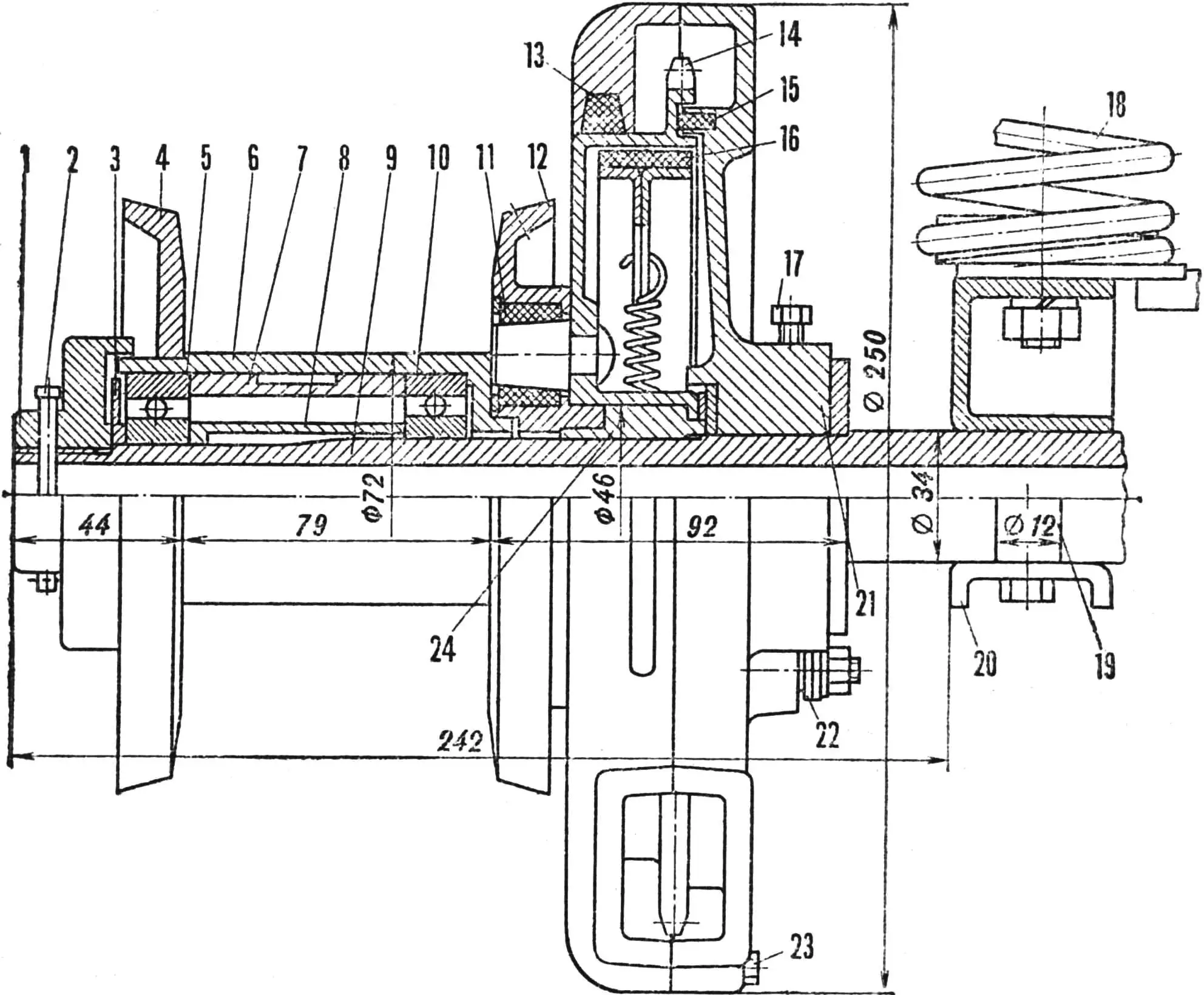
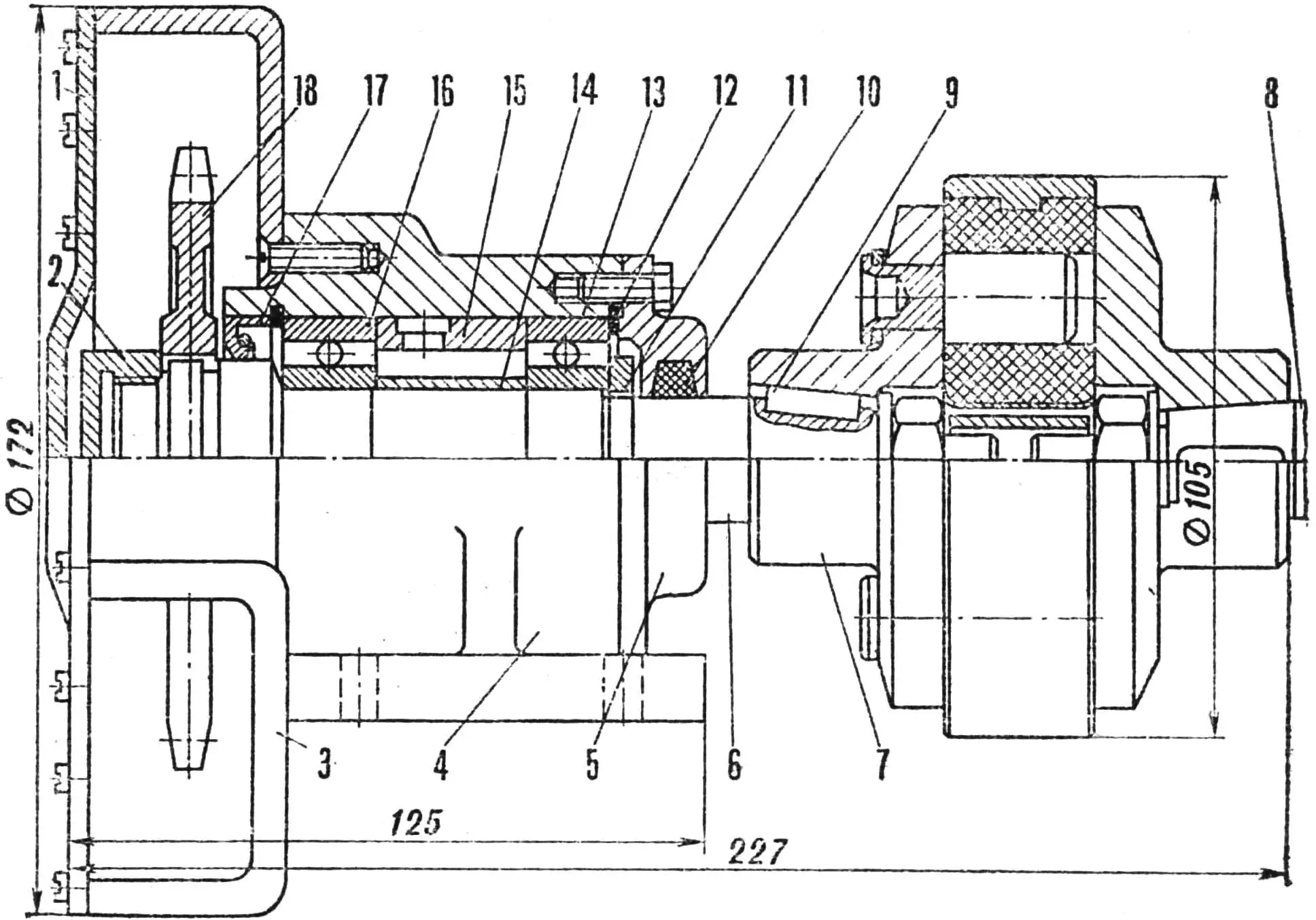
1 – shaft nut, 2 – cotter pin, 3 – adjusting washer, 4 – outer disk, 5 – bearing No. 305, 6 – hub, 7 – outer spacer sleeve, 8 – inner spacer sleeve, 9 – wheel axle, 10 – bearing No. 206, 11 – rubber bushing, 12 – inner disk, 13 – felt seal, 14 – driven sprocket, 15 – leather seal, 16 – brake shoe, 17 – M8 stop screw, 18 – suspension spring, 19 – spacer sleeve, 20 – suspension housing, 21 – sprocket housing, 22 – eccentric brake lever, 23 – housing fixing screw, 24 – sprocket hub (bronze).
Soft suspension performance is achieved thanks to the elastic mounting of the rear axle on microcar springs with friction dampers and rubber bump stops.
The suspension is cantilever, with triangular “arms” made from tubing. The pivot bolts pass through eyes on the sub‑frame, and the wheel axle is installed in the suspension housing and clamped against a stop by a fixing screw. The housing itself consists of box‑section parts — a base and a clamping plate — welded to the arms on one side and tightened with a bolt on the other.
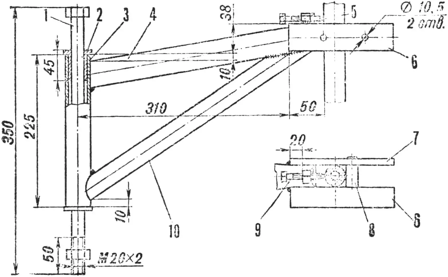
1 – sprocket‑housing cover, 2 – shaft nut, 3 – sprocket housing, 4 – bearing support housing, 5 – housing cover, 6 – intermediate shaft, 7 – coupling, 8 – cardan shaft, 9 – key, 10 – felt seal, 11 – locknut, 12 – ring, 13 – bearing No. 205, 14 – inner spacer sleeve, 15 – outer spacer sleeve, 16 – bearing No. 2505, 17 – seal, 18 – sprocket.
The driven sprocket of the rear wheel is mounted directly on the axle on a bronze bearing and is connected by pins (as in a coupling) to the inner disk of the wheel hub, in which matching windows are drilled for this purpose. In addition, both the inner and outer disks have holes for reinforced 5 mm spokes. The hub runs on two bearings, and the assembly is finished with a nut and cotter pin.
The tractor frame consists of two parts bolted together: the front from an Izh‑49 and a homemade rear sub‑frame. The latter is a space frame made from longitudinal and transverse beams and uprights. It is welded from tubing; a curved side beam acts as a support — it carries, on a gusset plate, the support for the intermediate shafts of the power transmission with their drive sprocket. Eyes and angle brackets for mounting the reducer block, the intermediate brake‑rod axle, the rear‑wheel suspension, the silencer, marker lights, the semi‑trailer hitch, and the body latches are welded to the frame.
The front fork of the tractor is stock. The front brake is hand‑operated; the rear wheels, with their standard brake drums, are braked by foot‑operated rods.
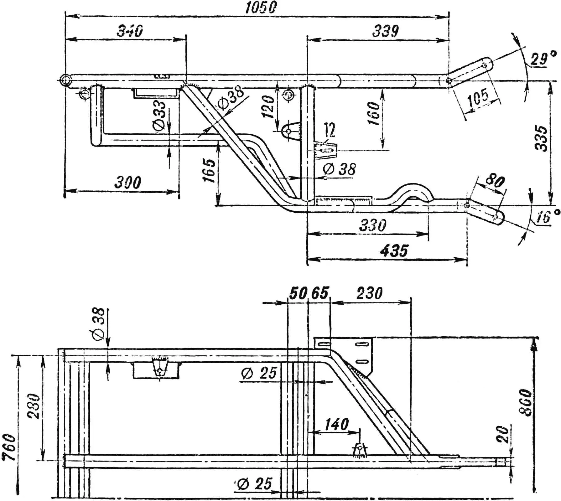
1 – suspension axle, 2 – bushing (bronze), 3 – support sleeve (tube 38×2), 4 – main arm (tube 38×2), blank length 340 mm, 5 – wheel axle, 6 – suspension base, 7 – clamping plate, 8 – stop, 9 – M8×60 screw, 10 – angle link.
A tipping cargo body with a payload of 200 kg can be mounted on the frame. The tractor can also tow a two‑wheel semi‑trailer carrying up to 600 kg. A special hitch joint is provided on the frame for connecting them.
“M‑K” advises
As reported by V. A. Melky, head of the Technical Inspection Department of the USSR State Automobile Inspectorate, amateur designers are not forbidden to use home‑built three‑wheel motorcycle‑tractors on their own homestead plots, but they are not allowed on public roads.
Given the widespread need in rural areas for light cargo transport, the USSR State Automobile Inspectorate has now approved technical requirements for motorcycle bodies built independently for sidecars, that is, instead of passenger “buckets”. Their payload may be up to 100 kg, but the total mass of the entire combination must not exceed the limit specified in the operating manual for that motorcycle type.
The body may be open or closed, with a lifting roof, with all sides folding down or only the rear one. However, overall dimensions are limited: external dimensions must not exceed 1800×550×300 mm. It is permitted to extend the sides when carrying “light” loads, but only so that the distance from the road surface to their top does not exceed 750 mm. Ground clearance also receives attention: its minimum value at full load must not be less than in the passenger configuration.
The materials for building the body are not strictly specified: any that provide adequate strength and reliability may be used. The body must be painted with durable, non‑washable paint. The sides, lids, and similar parts must be equipped with reliable latches. To secure the load, hooks and U‑bolts are provided, but they must not project more than 30–40 mm above the body panels. All edges and corners must be rounded with a radius of at least 2.5 mm to avoid injury in use.
The body must be mounted on the sidecar frame so that the distance from it to the motorcycle’s longitudinal axis does not exceed 350 mm and so that it does not interfere with control. The body must be attached at the same points as the passenger cabin.
Lighting equipment should preferably be factory‑made; homemade units must comply with the technical requirements “Signal lighting devices for motorcycles, motor scooters, mopeds and motorcycle sidecars” (OST 37.003.020‑78). These set out in detail the required illumination angles and visibility distances. Placement on a sidecar with a body must follow another standard (37.003.038‑77) — “Lighting devices for motorcycles, motor scooters, mopeds and motorcycle sidecars. Number, arrangement, colour, angles of visibility.” The devices are arranged as follows: a white position light and an amber turn indicator at the front; at the rear, a position light, stop light, and a non‑triangular reflector (all red); on the right‑hand side in the direction of travel, one or two amber reflectors. The latter must be mounted at a height of at least 250 mm above the road surface, and the other devices not lower than 350 mm.
A home‑built cargo body must be registered with the State Automobile Inspectorate. For this, the following must be submitted: an inspection report from the local branch of the All‑Union Voluntary Society of Motorists (VDOAM) confirming that the design complies with the technical requirements, sales slips and receipts from retail shops, commission shops, and other organisations that confirm the purchase of the relevant parts, assemblies, and materials. On this basis, a note is entered in the vehicle registration certificate authorising the operation of the presented body.
The technical requirements draw particular attention of amateur designers and those who will use such cargo bodies to the fact that carrying people, especially children, is prohibited. It is not allowed to change the design of the frames of trailers and motorcycles, their coupling components, or to manufacture frames‑chassis independently. Space must be provided for a first‑aid kit, a warning triangle, a tool kit, and a tyre pump.
“M‑K” 9’83, D. CHERNYSHYOV, Kasli, Chelyabinsk region.
A motorcycle and a car are different machines. First and foremost, in terms of comfort. But can the advantages of two-wheeled transport be combined with the convenience of a passenger car? It turns out they can. Such two-wheeled machines—autorollers or motocars—are sometimes seen on the streets. We suggest you build one of these designs yourself.
This vehicle is a scooter with an engine of about 50 cm³ displacement, which, unlike traditional two-wheelers, has a light plastic body with a folding top, a seat almost like in a car, and two additional small wheels that can be raised and lowered like landing gear on an aircraft.
Let’s get to work. We’ll start with the frame. Obviously, you can’t build it without a welding set. You’ll need steel tubes with an outside diameter of 34 mm and wall thickness of 2.5 mm, tubes 22 mm in diameter (same wall thickness), and a front telescopic fork from any moped or scooter. The frame is designed for wheels from a Riga-built mini-moped, but scooter wheels will work too. You’ll also need sheet steel about 2.5 mm thick.
First, draw the frame full size. This will let you cut the blanks correctly and accurately from the drawing and finally fix the main dimensions of the parts.
As the drawings show, the autoroller frame is backbone-type and consists of a welded two-tube L-shaped spine that also acts as the rear wheel fork. To each tube, 4 mm thick steel plates with longitudinal slots for the axle are welded. We recommend cutting the slots after the plates are fitted—this helps get the work more accurate.
Now join the rear wheel to the frame tubes, tighten the axle nuts firmly, and mark where the bends will be. For a small bend you don’t need to pack the tube with sand—a tube bender is enough. After fitting, the tubes are welded at two or three points.
Next, fit the wheel in the front fork and fix the fork to the floor with wooden battens in the position shown. In the same way, set the frame spine with the rear wheel. Temporarily secure the spine to the steering column with soft copper wire. Check the wheel alignment carefully—they must lie in one plane. If correct, tack the spine to the steering column in two or three places. After final fitting, weld all joints fully. At the front, the spine-to-column joint is reinforced with gussets cut from 2.5 mm steel sheet.
The rear engine mounting bracket is cut and bent from 3 mm sheet steel. Do this in place: first cut a cardboard template and only after fitting make the metal blank. Fit the front bracket the same way.
After machining, attach the bracket to the engine and fix it on the frame with wire. Alignment must be checked again—the cylinder axis must lie in the frame’s plane of symmetry, and the carburetor platform must be level. After tacking the brackets, do a final check and complete the welding with the engine removed.
The frame base is ready. Add the cross tube that serves as the pivot for the extra wheels and small pads for the driver’s seat. The frame is then fully assembled.
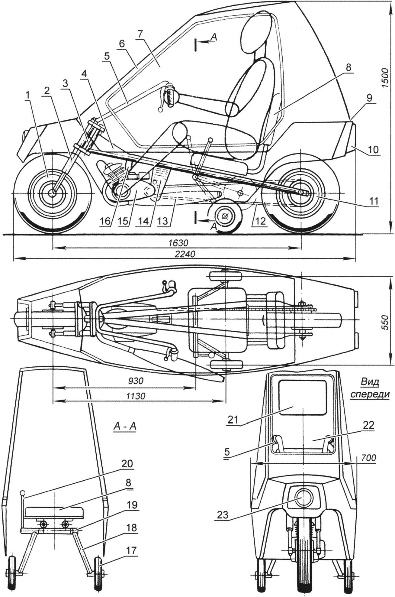
1 – front wheel (from mini-moped or scooter); 2 – front wheel fork (from any moped); 3 – frame steering column; 4 – reinforcing gusset from 2.5 mm steel sheet; 5 – handlebar (from mini-moped); 6 – folding glazed cab – “canopy”; 7 – block “glass” (Mylar film); 8 – driver’s seat (metal chair top, padded with foam and vinyl); 9 – hinge of folding cab (“canopy”); 10 – rear lights and stop lights (from motorcycle or scooter); 11 – rear wheel (from mini-moped or scooter); 12 – bushed roller chain (from two standard moped chains); 13 – muffler (from any moped); 14 – rear engine bracket (bent from 3 mm steel sheet); 15 – engine (Sh-58 or Sh-62 type); 16 – front engine bracket (bent from 3 mm steel strip); 17 – side support wheel; 18 – chassis strut (22 mm tube); 19 – support wheel pivot; 20 – chassis wheel raise/lower lever; 21 – rear window (Mylar film); 22 – front window (Mylar film); 23 – front headlight (from any moped)
For the extra wheels’ axle, choose a tube whose outside diameter allows it to rotate freely in the pivot. If you can’t find one, use a smaller tube or rod and compensate the gap with rings cut from plastic hose—they work well as plain bearings.
The chassis strut is made from 22 mm outside diameter steel tube. Weld a bushing to one end and a turned steel axle to the other. On the left strut, weld a short 10 mm steel rod with a thread for a plastic handle. This is the chassis control lever.
The extra wheels must lock reliably in both extended and retracted positions. The mechanism is straightforward; we suggest designing it yourself.
Chassis wheels can be from a children’s bicycle. Prefer rubber “balloon” or solid-rubber (not plastic) tires up to 200 mm in diameter.
The autoroller fuel tank is a 5 litre plastic or aluminium can. Fit a standard motorcycle fuel tap with sediment bowl and mount it at the rear of the body. Drill a vent hole in the can cap.
The body is plastic. The structure is built from 20×20 mm wooden battens.
The lower part of the body is like a small boat hull. Assemble the transverse frames from battens, then add the longitudinal battens per the drawing. Then skin the frame. Kitchen furniture plastic (sold in hardware stores) is a good option. Use epoxy for gluing the frame and skin. If you can’t find plastic, thin plywood or hardboard up to 3 mm is acceptable, or other options.
The upper part is built similarly. Glazing is transparent film of the kind used for model aircraft. Make window frames from 10×20 mm battens with spacers. Place the frame on the film, cut with a 20 mm margin, fold the film over and glue to the frame with BF-2 adhesive. Iron the joint with the iron set to “silk”. Then screw the frame into the window opening.
The window may not look perfect at first—Mylar is stiff and hard to tension. Use the iron set to “cotton” or “linen” and iron the film; it will tighten and flatten.
Final finishing is simple. With plastic skin, fill joints with epoxy filler (epoxy glue and talc) and paint with nitro primer then nitro enamel. With plywood or hardboard, level with filler, then cover with a layer of glass cloth and epoxy and paint.
Pay special attention to the controls. They are much like a moped’s. On the handlebar (from a Riga mini-moped) fit the throttle, front brake lever (right), and clutch lever (left). If the engine has a manual gear selector, mount it on the left of the handlebar.
The engine starter needs modification. At minimum, reposition the kickstarter lever on the splined shaft so it’s easy to kick from the seat. Better is a cord starter: fit a pulley on the splined shaft with two or three turns of nylon cord, run the free end to a convenient spot for a left-hand pull, and add a T-handle.
The last control is the chassis raise/lower lever—best under the driver’s left hand. The brake pedal for the rear wheel goes under the right foot.
For the first runs, leave the cab (“canopy”) off. Sit comfortably (chassis extended), put the gear in neutral, and start the engine. After warm-up, move off in first, then second. Retract the chassis only when the autoroller feels stable. Operating the extra wheels will feel odd at first but is easy to learn.
When using the autoroller, remember the engine runs cooler than on a moped. Ensure the cylinder cooling opening in the body is in the front wheel well, directly opposite the cylinder, and larger than the cylinder. If cooling is insufficient and the engine overheats, consider forced cooling. It’s not hard: remove the right crankcase cover and fix aluminium blades for a centrifugal fan on the flywheel/generator rotor. Make an air duct from bent aluminium sheet or from cloth and epoxy on a foam former, filled with plasticine or non-hardening putty.
«Modelist-Konstruktor» No. 6’2014, I. YEVSTRATOV, engineer
Recommend to read
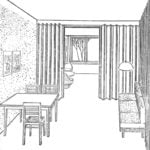 THE WALL IS “WALK” AROUND THE APARTMENT
One-room apartments of the inevitable universality of the dwelling. The only room is to serve as the living room, bedroom and office. To combine such heterogeneous requirements is...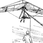 Hang glider pilot’s “desk”
Training on the simulator is part of a complex of organizational, methodological and technical measures of the Kaunas Hang Gliding Sports and Technical Club DOSAAF, aimed at improving...
