MULTIPURPOSE AND MULTINATIONAL

MULTI-PURPOSE AND MULTINATIONALFrench carrier-based aircraft BREGUET Br.1050 Alize. The need for double decked multi-role aircraft, capable of reconnaissance, and search and destruction of submarines, came the Navy of France with the deployment of the construction of new aircraft carriers. The order for the development of such aircraft placed on firm Breguet, and such a choice of the contractor was not accidental. In 1946 — 1952 Breguet has worked to develop a plane Breguet Br.960 Vultur and its anti-submarine variant VG.962 AM. It is quite logical that the new aircraft began to design on the basis of tested machines.


The new plane looks a little different from the original samples was a completely new development. The main changes concern the power plant and the layout of the fuselage. The design of the wing and tail has changed slightly.
 
The projected aircraft was in accordance with the firm numbered to another marking Breguet.966. But for some reason the new machine is assigned a sequence number 1050 and, accordingly, the name Breguet. 1050 (Br. 1050).
 
On the first sketches of the aircraft with the designation Breguet. 1050 still largely discernible the outlines of their predecessors. The tail is fully consistent with the Breguet Br.960 Vultur. The cockpit glazing was the same as the VG.962 ASM, only the canopy of the lantern consisted of four sections. Wing — F6 and F6 bis large cigar-shaped fairing where the retracted main landing gear, was released milongero the volumes under the fuel tanks. Also, the fairings provide additional margin of longitudinal and directional stability.
 
All the same, the main difference between the new aircraft and its predecessors consisted in equipping its single engine turboprop Rolls-Royce Dart instead of a combined power plant, consisting of TVD Armstrong-Siddeley Mamba and Rolls-Royce Nene. The vacant space in the fuselage allowed to post in this three-dimensional search radar antenna. In addition, the Dart engine had considerable potential for upgrading — particularly to increase capacity. In the future, instead of the Dart R. Da 6 rated at 980 HP involves the installation of advanced engines Dart R. Da 20 power of 1600 HP or Dart R. Da 21 1950 power HP Another advantage of the single-engine version was supposed to increase range by decreasing fuel consumption.
Before building the prototype of the Breguet firm has spent a considerable amount of aerodynamic experiments on models and layouts of the aircraft, true to scale 1:8, 1:2,5, 1:16 and 1:20. During the blowdown the aerodynamic configuration of the car was made a lot of changes. So, increased the size and changed the configuration of the tail, which was supposed to improve longitudinal and directional stability of the aircraft given the increase in capacity of the power plant, picked up the wing profiles, the configuration of the fairings of the nacelles, which stands out of the main chassis. Models also were selected surfaces, ailerons and flaps. All this work has allowed to avoid significant changes in the structure of the aircraft at the stage of prototype testing. Moreover — given the opportunity not to build it, and all the technical solutions to work on already assembled the second prototype HS.960 received by the time the marking of VG.965. On the plane already assembled a three-man cockpit and avionics, which subsequently was set on Breguet. 1050.

 
Anti-submarine Alize aircraft Br.1050 of the 210 squadron of the Indian Navy
 
With regards to the period of the financial capacity of the company, this solution will significantly reduce costs and stay within the allotted for the development of term — 4 years (order entered in 1955, and the first serial slopet took to the air in 1959). It should be noted that five cars with numbers from 01 to 05, built between 1956 and 1959, were actually pre-production aircraft, not prototypes (at least officially). At this time the aircraft was established followed by the name of Breguet. 1050 Alize.
 
The first pre-series car (No. 01) had the following differences from the prototype aircraft:
 
tailplane of increased area;
 
keel, the original oval shape was trapezoidal with rounded corners;
 
a long and spacious fuselage weapons bays in its lower part;
 
re-designed the cockpit for radar operator.
 
On the plane, in the lower part of the fuselage, just behind wing mounted radar antenna in the large radio transparent fairing for the work she produced, and at the end again retracted into the fuselage. This system, developed on the VG project.960 ASM, although weighted design was still preferable to inpatient, due to better aerodynamics was the resulting gain in speed and good directional stability in flight.
 
There was a problem of selection of the position of the engine. With this question, the engineers at Breguet faced when working on VG.960. The engine was not supposed to marry the fuselage to provide a good overview of the pilot. In addition, it was necessary to maintain the operational characteristics of the aircraft in terms of its deployment in a limited space of an aircraft carrier. Not immediately identified and the place of exhaust gases. For Breguet.1050-01 and 02 exhaust pipe took the exhaust to the right side of the fuselage, under the wing, but the hot air reflected from the flight deck, gave much trouble to the attendants. To eliminate this drawback by cars with numbers from 03 to 05 exhaust pipe from the engine is brought above the wing. This solved the problem and the right side exhaust pipe has become a distinctive feature of all serial Alize.
 
Pre-Alize (Br.1050-01-05)
 
VG. 1050-01 took to the air on 5 October 1956. First flight on the new machine was made by the test pilot of Breguet Yves Bruno. For several days the pilot has completed a series of flights in which the aircraft showed good handling in the air and on takeoff and landing. During flight tests, which took place almost to the end of 1957, significant deficiencies in the design and behavior of the aircraft have been identified. The only trouble is, manifested already in the first landings, was overheating of the wheels of the main landing gear, but the engineers overcame it soon, adding to the braking system additional a couple of CD’s.
 
In early 1957 the aircraft was tested in France, and in may flew to England, where at the air base Bedford where trained British pilots of carrier-based aircraft, were practicing take-off and landing using catapults and arresting gear. Tests in England lasted until November 15, 1957.
 
Later the aircraft was developing a new turboprop Rolls-Royce Dart R. Da 20 power of 1600 HP and a cooling turbine of more modern design. On VG 1050-01 was first established by the newly developed American radar APS 33 with retractable radio antenna in the fairing.
 
In 1960, the first of Alize transferred to the aviation school in Rochefort, where he later finished his career as a primary training aircraft pilots and radar operators of carrier-based aircraft.
 
VG.1050-02 made its first flight on 22 December 1957. The aircraft had conducted tests of the radar GTP and other electronic equipment. But the main problem, which was solved by plane, became leader of the test. One year of HS.1050-02 have flown more than 1,300 hours, which gave the opportunity to determine the reliability of the most loaded components and assemblies, ask them overhaul and assigned the resource. According to the results of machine maintenance ground technical staff have drawn up technical documentation.
 
Multi-deck aircraft BREGUET Br.1050 Alize
 
Multipurpose carrier-based aircraft BREGUET Br.1050 Alize
 
In December 1958 VG.1050-02 first of the family Alizé carried out a takeoff and landing on the deck of an aircraft carrier Arromanches.
 
VG.1050-03 was originally equipped with engine Rolls-Royce Dart R. Da 20. But even prior to the flight, the aircraft set Dart 21 (R. Da 21) with a power of 1950 HP and a new oil radiator. The engine was equipped with new four-bladed screw Breguet-Rotol BR.4, developed by one of the departments of the company Breguet.
 
The first flight took place on 19 April 1957. At the end of 1958 VG.1050-03 the same as the first Alize was flying over to England, where at the air base in Bedford conducted a new test cycle for the ejection take-off and landing using the aircraft braking system.
 
In December 1958 VG.1050-03 practiced taking off and landing from the deck of the English aircraft carrier HMS Eagle as opposed to the outdated and small French Arromanches, he was a truly modern ship.
 
Later on the plane, exploring the techniques and methods of work with the American radar APS 33.
 
VG.1050-04 immediately manned engine Dart 21 (R. Da 21). The construction of the aircraft was completed in may 1957, and on June 21 machine first took to the air. This aircraft was to be carried out strength and vibration tests. Later on the machine worked out the arms, tested the operation of the system of opening of the valves weapons bays simultaneously with the harvesting and production of radar antenna, determined by the handling characteristics of the aircraft in these flight regimes.
 
Breguet Br.1050 Alize
 
Breguet Br.1050 Alize
 
Breguet Br.1050 Alize:
 
1 – keel (original version); 2 – air brakes; 3 – the exhaust pipes of the engine; 4-antenna radio (original version); 5 —cabin Windows of the radar operator; 6 — air intake air-conditioning system; 7 — right engine hood; 8 — inlet of the turbine starter; 9 — radar in the released (operating) positions; 10 is a modified keel; 11 — modified the radio antenna; 12—sliding part of the canopy of the Navigator; 13 — castles hood; 14—fairing landing lights; 15 rocking of the flaps; 16—radar in the retracted position; 17—trimmers rudder; 18 — the rudder; 19 – antenna navigation system; 20—antenna radios; 21 — visor canopy; 22 — cooling air intake of the engine; the 23 four-bladed variable-pitch propeller; a 24-fold niches cleaned the wheels of the front landing gear; 25—antenna radios; 26– exhaust pipe; 27 — wing pylons; 28 — fold compartment weapons; 29 — the arresting hook in the retracted position; 30—foot pegs; 31 —the cockpit canopy in the open position; 32—sliding part of the canopy of the radar operator; 33—antenna tail warning system on the irradiation of the aircraft RLS of enemy; 34 — hydraulic cylinder; 35—brake hook to a released position; a 36 —fold compartment arms in the open position; 37—strut main landing gear; 38— pissing cleaning the main landing gear in the open position; 39—system antenna warning receiver of the plane of the enemy radar; 40— retractable ladder in working position: 41 —fold niches removed the front landing gear from the covered position; 42 —hour front landing gear; 43— hook ejection start; 44 — hatch styling retractable ladder; 45—flap access to the filling hydraulic components; 46—surveillance radars; 47 —docilely stabilizer; 48 —engine General Electric T-58:49 — accommodation hydroboil additional weapons bays; 50 – wheel main landing gear in the retracted position; 51—gearbox engine: 52 — transmission shaft; 53 is a transparent fairing of the landing lights; 54 – the hood locks; 55—hood nose compartment equipment; 56 Kil is larger; 57— the exhaust pipe; 58 — hood; 59—the variable-pitch propeller

 
At the end of 1958 VG.1050-04 and VG.1050-03 took part in the campaign against the English aircraft carrier HMS Eagle, in which fully tested the operation of Alize on the deck of an aircraft carrier.
 
VG.1050-04 became the first aircraft of this type, capable of carrying all provided for him a set of weapons. During testing, it set a radar CSF (DRAA 2A).
 
From February 1959, the aircraft was used in the test center aviation of France as a flying laboratory.
 
VG.1050-05 fully consistent with its predecessor — VG.1050-04. The only difference was a modified hydraulic release system of the radar antenna. The construction of the aircraft was completed in June 1957 and 1 August of the same year he made his first flight.
 
On this machine they worked out the ways of applying various anti-submarine weapons. Testing was completed in January 1959. A few months later, during testing on the deck of the aircraft carrier Arromanches aircraft lost speed and fell into the water. The crew were rescued, but the plane was lost.
 
Alize in a series of orders and delivery
 
The initial order received by the firm Breguet in new aircraft from his command Navy, made of 100 machines, however, given the reduction in the military budget, in 1958, the order was reduced to 75 units.
 
Suddenly interest in the new aircraft showed Indonesia and India, expressed a desire to purchase the Alize. Indonesia received the refusal of the French government, which feared the use of their aircraft in the conflict with the Netherlands — an ally of France. At the same time selling India twelve Alize was approved.
 
VG.1050 were interested and Navy of Brazil, which was needed carrier-based antisubmarine aircraft carrier Minas Geraes. In 1960, Brazil had carried out a comparative test of VG.1050 Alize and Grumman Tracker. Preference was given to the latter, which had more potential for modernization (by the way, the upgraded aircraft Tracker is currently still are in service with the naval aviation of Brazil).
 
Thus, the total number of serial Alize was 87 cars and 5 pre-production copies. The first production Sh.1050 was officially transferred to the Navy 31 March 1959, the last on 19 July 1961.
 
In the service
 
75 Alize passed to the aircraft fleet of France in 1959 — 1961, had a sequence number 1 — 61, 64,65, 68 — 70, 72 — 77, 80, 86 87. The new aircraft entered service with three flotillas: 4F, 6F and 9F. Earlier, the pilots of all three flotillas (squadrons) were flying outdated American aircraft Avenger.
 
At the end of the training squadrons flew to their places of permanent deployment, but in its place they practically were not — most of the time the squadron was located on one of the three aircraft carriers — the Arromanches, Foch and Clemanceau or. The first carrier was mainly used for practicing takeoff and landing using catapult staff and arresting gear.
 
In addition to its main tasks (exploration and undersea search pidok), short Alize in marine campaigns, they sometimes had to participate in special events. So, the machine of squadron 9F double-patrolling and monitoring the areas of the testing by France of nuclear weapons in the Pacific ocean.
 
In accordance with the plans of the aircraft fleet, aircraft, which were assigned to the squadron, carried out a retraining and training of new crews flying on VG.1050 Alize.
 
It should be noted that excessive amounts Alize (75 samofatov for the three squadrons in the state of 12 cars) allowed in case of mobilization in wartime quickly doubled the regular number of these aircraft on Board the carrier. For this reason, VG.1050 were involved in such tasks as communications, towing air targets and the training of technical personnel.
 
By mid-1972, squadron 9F rearmed for new equipment. In the composition of the 4F and 6F squadrons VG. 1050 Alize remained in service until the late 1980s, after which it was replaced by helicopters SA.321.
 
During the operation Alize has earned the respect and love of flight and technical staff. Pilots noted good handling, ease of placement in the cockpit and the strength of the structure. Technique praised the machine for ease of use and convenience of approach to the engine. The only thing that could be attributed to the shortcomings of aircraft — small engine response. It made pilots very carefully control the speed at takeoff and landing. The engine reacted to the loss of speed late. For this reason, was lost pre-Alize No. 05. It was believed that in the course of serial production of this disadvantage will be eliminated. But as it turned out, completely get rid of it failed.
 
The plane was easy to manage. Flight program for retraining on Alize took only 15 days (30 flight hours). After two export potatoe pilot allowed for independent departure. After a 15-day training, the crews continued flight training on aircraft carriers.
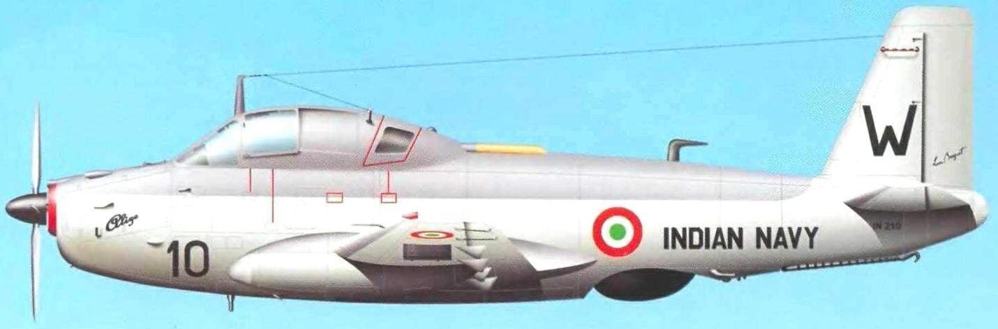
 

Indian Breguet 1050
 
Twelve Alize, which is a part of aircraft of the Indian Navy, IMAPI serial number 62 to 85. Alize the first of this batch (No. 62) first took to the air on 21 October 1960 and was solemnly transferred to India in January 1961. The remaining aircraft of France gave India in the next four months.
 
All aircraft intended for the Indian aircraft carrier Vikrant, which is India priobretu the UK in 1961. To the Indian phase of its service, the carrier was called Hercules (R11). The ship, built in 1945, belonged to the class of Glory (full displacement of the aircraft carrier — 19 500 tons maximum speed — 24.5 knots). In the air group, in addition to the squadron of four Alize, included fighter-bombers, Sea Hawk (10 cars) and four multipurpose helicopter Allouette).
 
The loading of the aircraft on the aircraft carrier was carried out in Malta, after which Vikrant has left the shores of India. All Alize joined the 300th and 310th anti-submarine squadrons.
 
In 1968, two VG.1050 Alize with the inscription on Board the “Indian Navy” was transferred to France in return two planes decommissioned from the Navy. Two Alize (#14 and # 18) from the aviation of the French Navy became the exhibits of the aviation Museum.
 
VG.1050 from structure 310 squadron took part in two short Indo-Pakistani wars of 1965 and 1971. Particularly active planes used in 1971. During this period, the aircraft carrier Vikrant was stationed off the coast of Bangladesh. The Alize was used for night attacks ground targets, minefields and patrols of coastal waters. During one of these sorties the crew Alize managed to sink a Pakistani submarine of the Daphne type, which also had a French origin. The boat was on the surface and was destroyed by bombs and rocket attacks. During the entire period of hostilities VG.1050 was performed in 70 sorties. Exposed these aircraft mines blown before the end of the war 11 ships. Bomb and missile attacks, the crews Alize, except the submarine managed to sink six gunboats, armed steamers, and boats, as well as eight commercial ocean-going vessels.
 
One of the Alize the Indians lost. Pakistani F-104 intercepted the Indian aircraft South-East of Karachi, where he was performing a patrol flight. From a direct hit by a rocket Alize exploded in the air.


On the basis of production aircraft was developed in two modifications, which have remained the same powerplant and fuselage, but there were significant changes in the composition of radio-electronic and other equipment and accordingly had to perform specific tasks. The first of these aircraft electronic intelligence and electronic warfare (EW). This modification involves the replacement kit regular electronic equipment.

The second modification — towing air targets.
 
However, further drawings did not get. It quickly became clear that any VG.1050 after minor modifications, performed by the squadron technical staff with the use of standard equipment, successfully able to perform these tasks.
 
So, to tow aerial targets for the aircraft were nominally the towing device, and a target was fixed on any pylon under the wing.
 
Experiments on the conversion of the anti-submarine Alize aircraft EW was carried out by car No. 44. With this purpose, the crew included the operator of the radar equipment and Navigator, and on the pylon under the right plane of the assembled container with the EW equipment. The experiments confirmed high efficiency of such aircraft.
 
Changing the variant weapons, the Alize can be used as a Director of the marine min For this in the standard VG.1050 downloaded six minutes (two in the bomb Bay, two on the pylons under the center and two on pylons folding wing panels).
 
As it turned out, the standard plane, and can perform other tasks without the creation of his new modification: in particular — to communicate and to transport goods and passengers. To this end, since the plane was shot electronic equipment, and vacant the compartment was used as a cargo. If necessary, up to eight passengers can fit in the cockpit. However, the crew was reduced to one pilot.
 
There was another drastic modifications to Breguet. 1050 Alize.
 
Br.1050 A. E. W.
 
In 1957, the Navy has considered using Alize as early warning aircraft (AWACS). In connection with the funding shortfall proposed use with minimal alteration of the structure. The work on improvement of this machine was conducted over two years and was completed in 1959.
 
Firm Breguet was offered two possible options of solving the problem. Both options involved the use of American radar APS-20 and navigation system AN/ASA.13.
 
In the first case, the radar antenna was prepagadas to place under the fuselage, as American aircraft Skyraider, which was already used in the naval aviation of the USA. This decision led to the reconfiguration of the chassis (had to increase the height of the uprights), replacement brake hook and units of ejection start.
 
In the second case, the radar mounted in a fairing on the back of the fuselage, just behind the cockpit. With this arrangement, the radar has been necessary to replace the single-fin empennage on posted dvuhkilevoe, since the first was completely dimmed by the Radome. Thus decreased the efficiency of the rudder and reduced directional and longitudinal stability of the aircraft.
 
Carrier-based aircraft Breguet Br.1050 Alize
 
Carrier-based aircraft Breguet Br.1050 Alize
 
It should be noted that at the upper antenna locations the plane could make a patrol at a lower altitude. While radar is better viewed airspace. Such placement of the antenna was considered more promising and it was decided to consider this proposal. However, all work on the version VG.1050 A. E. W. ended in the design phase. Not built even a life-size model. All agreed the lack of money. Firm tried to save the project and turned to the command of the Fleet with a proposal to remake a version of A. E. W. one of the serial machines. But the military did not want to sacrifice even one anti-submarine aircraft.
 
In 1962 work on VG.1050 A. E. W. resumed. The program was called Spirale. It was assumed that the aircraft would be twin-engined on the model developed in this time, the firm Sh.123.
 
Of the characteristics that were introduced into Br.1050 A. E. W., it is known that in accordance with the terms of the Fleet’s maximum takeoff weight was not to exceed 8.2 tons. Stock toppila precept was 2,800 liters.
 
The twin-engine project Alize
 
At the end of 1956, the Breguet firm has proposed its initiative variant of the twin-engine VG.1050. It was supposed to replace the engine in Dart, located in the forward fuselage, two engines General Electric T-58 with a capacity of 1050 HP each installed in the front of the fairings nish cleaning the main chassis.
 
American engines General Electric T-58 otlichish small size and less fuel consumption. However, the nose of the fuselage, freed from the engine, could be used for additional electronic equipment. Although the new plane was supposed to have higher capabilities for further upgrading, it is never built. A deeper study showed that the production and operation of the aircraft will be much more difficult and expensive.
 
It was suggested to build a twin-engine Alize mainly for export, but this plan was not implemented — in the way the creators of the machine again raised the lack of funding for the project.
 
Signs of the aircraft
 
French VG.1050 carried on the fuselage and the standard wing markings of naval aviation and large side numbers, legible from a distance. All this was applied at the factory.
 
To distinguish the planes last upgrade to the onboard serial number was added the number “100”. So Alize No. 37 after performing modifications and changes in the equipment carried serial number 137. After upgrading all the machines back to the original numbering.
 
Br.1050 Alize
 
Br.1050 Alize
 
Refer to drawings Br.1050 Alize:
 
1 — the landing lights; 2 — light alarm-released position of the nose; 3 — used; 4 — wheel front landing gear; 5—the shirt of the cylinder of the shock absorber; 6—polubil-CA; 7 — wheel; 8—pull and retract the front landing gear; 9—operational hatches; 10—folding console wing; 11 – LDPE; 12 — ANO; 13—Aileron; 14 — trimmers Aileron; 15 sections of the flaps; 16 cap filler fuel tank; 17 — stabilizer: 18—handlebar height: 19 — trimming of the Elevator; 20 – sliding part of the canopy operator: 21—sliding section of the canopy Navigator and pilot; 22 glass lantern; 23 the dashboard of the cab Milota; 24— control knob; 25 — pilot’s seat; 26 canopy; 27 – intake air-conditioning system of the cabin crew; 28 – instrumentation cockpit Navigator; 29—the co-driver seat; 30 — stick sealing lamp; 31 —sliding PA R t of the cockpit canopy; 32 handle the opening of the lantern; 33 — fold niches nose landing gear; 34 — hooks ejection system start; 35, the main pole; 36—fold additional weapons bays; a 37—line of folding wing; 38 console pylons; 39—traction control Aileron trimmer; 40 — rocking of the flaps; 41 maintenance hatches; 42 —brake hook; 43 radar; 44 protective case; 45 Kil; 46—rudder: 47— trimming the rudder; 48—left the bonnet in the open position; 49—motor mount; 50 engine; 51 —reducer of the engine; 52 stop; 53 — Parking lights; 54—radiation detectors; 55 console wing in the folded position

 
The aircraft sold to India, carried on-Board the designation “English” from IN201 to IN212. Each factory matched number registration number code.
 
No. 62 — IN201
No. 63 — IN202
No. 66 — IN203
No. 67 — IN204
No. 71 — IN205
No. 78 — IN206
No. 79 — IN207
No. 81 — IN208
No. 82 — IN209
No. 83 — IN210
No. 84 — IN211
No. 85 — IN212
 
the sign was applied to the inscription INDIAN NAVY, and the keel was rastopilsya additional letter code (e.g., IN bore 202 code W).
 
Design description
 
The fuselage is semi-monocoque design, the elliptical cross-section. Fuselage length of 13.86 m, the height is 1.94 m, width -1,71 M.
 
Technologically, the fuselage was divided into three sections: the nose (engine compartment), Central (compartment cockpit and weapons) and tail (cut the radar antenna). In the fuselage there were multiple sealed partitions, ensure the buoyancy of the aircraft during a forced landing on the water. Access doors and removable panels provide easy approach to the power plant, hosts, units, and equipment of REO.
 
In the forward section of the steel motorhome mounted turboprop Rolls Royce DART.21. Engine mount is attached to the second (power), sealed bulkhead.
 
In the lower part of the first power frame is attached to the node for installation of the nose landing gear. At the bottom of the bow section had a niche of cleaning the front landing gear.
 
The Central section was limited to two sealed power formers. The upper part of the section was occupied by the cockpit, designed for three people. The crew consisted of the pilot (located on the front left seat on the flight), Navigator-weapons operator (to the right of the pilot) and radar operator (pilot and Navigator). In flight, the crew members could move around the cabin. So, the Navigator could take the place of the operator and Vice versa. Behind the seats of the pilot and Navigator were installed on the equipment control and tracking radar indicators and screen. Cabin floor dividing the Central section of the cockpit and weapons bays, were power. This made it possible to abandon a large number of longitudinal strength members.
 
Weapons bays 5 metres in length was closed with two doors, driven by six hydraulic rams (three on each side). It housed bombing and torpedo weapons, as well as depth charges and mines. In addition, it was possible to mount two additional fuel tank.
 
In the tail section of the fuselage housed a retractable radar antenna and the section served as a basis for attachment of fin and stabilizer. In the lower part of the section was installed a brake hook. The power set of the tail section consisted of 16 frames and stringers. Retractable radar antenna with a diameter of 1.3 m viewscapes and retracted into the tail section through hydraulic drive. The antenna was attached to two steel hoops, which allowed to fix it in any intermediate position.
 
The wing cantilever, two-spar, trapezoidal shape. The wing span of 15.6 m, elongation — 6.8 m wing Profile — Breguet L20. Wing setting angle +2°30’ in anthropinou part and +1° in the terminal part of kripa. Technologically the wing was divided into three sections: a center section and two foldable console. Centropen wing had a wingspan of 6.6 meters and consisted of two half-planes. Two longitudinal members, sheathing panels and power wing ribs formed in centroplane part of the wing volume in which were placed four rubber-sealing fuel tank.
 
Wing folding, the drive of the folding mechanism — hydraulic. Control and position locking consoles were made from the cockpit.
 
Across the rear edge of the wing from the fuselage to the ailerons located three-position slotted flaps divided into four sections. The two inner sections were mounted on the wing center section and two folding consoles.
 
The flaps can be in three positions: “retracted” (0°), “takeoff” (35°) and “landing” (55°). The scope of the flaps of 4.1 m.
 
At the end parts of the wing mounted ailerons. Angles of Aileron deflection is 25°. Throughout their scope had automatic trimmers, operated hydraulically.
 
Strut main landing gear retracted into the center section in a cigar-shaped fairings. They turned forward. In the front part of the fairing housed the electronic equipment.
 
Centroplane bottom part of the wing could be installed twice, and folding consoles — six pylons for attaching various types of weapons.
 
Both folding consoles were installed rods with LDPE. On the right hand console — the main, on the left — the emergency (back-up).
 
The tail of the plane normal scheme, a trapezoidal shape. Keel dvuhkonturniy. The rudder — horn compensation. The height of the vertical stabilizer — 2.5 meters. Throughout the span of the rudder was located operated trimmer.
 
The horizontal tail consisted of the stabilizer and the Elevator. The scope of the stabilizer 5.8 meters, profile — type L. Breguet 14. Cross-V regulator — 0°. The installation angle +2°15‘.
 
On the first pre-series aircraft rudders height and direction were implemented without the use of servos and actuators, but since the VG.1050-04, control system mounted hydraulic actuators to reduce the load on the pedals and the control stick.
 
Landing gear normal scheme with nasal support — company Hispano-Suiza. All racks have the same wheel sizes 650×10”, while the main racks were installed in two wheels with pneumatic disc brakes and on the front is one of the freedoms neolentinus. The front Desk was cleaned about turning back, main pillar — turn forward. The system of harvesting and the landing gear is hydraulic, and the opening and closing of the flaps is carried out hydraulically.
 
The distance between the pillars the pillars was 4.9 meters, and the bow between the posts and main supports — 4,4 meters. Landing gear designed for a maximum landing vertical velocity of 4 m /sec.
 
The power plant of the aircraft had turboprop engines Rolls-Royce Dart R. Da 21 with the rotation speed of the rotor 15 000 rpm.min and a shaft power of 1950 HP, as well as from fuel and oil systems. The exhaust pipe of the exhaust air from the engine was right on the flight, above the wing.
 
The colour schemes of the aircraft Alize VG.1050 from 6F flotilla of the French Navy
 
The engine was completed with four-bladed metal variable-pitch propeller Breguet-BR 4-1000 Robot with a diameter of 3.35 meters. Change step was carried out at turn of the lever on the handle control engine (ORE) hydraulically.
 
The engine is mounted at four points on the steel tubular Motorama fixed on the power sealed bulkhead No. 5. The nodes of the engine mounts had the rubber cushioning. The engine supplied by the injection system methanol-water mixture, allows you to maintain engine power at high temperatures. It should be noted that this system is well proven in the tropics, supporting the frequency of rotation of the rotor within 14 700 rpm./min.
 
Control system for military engine variant differed from the “civilian” — it can maintain the turbocharger speed constant (15 000 rpm) regardless of the pilot operation of the engine, allowing more sharply to move ORES.
 
The engine was used in aviation kerosene grades of TR-0, TR-4 or TR-5, and mixtures thereof in any proportion. Total fuel capacity — 2100 litres. Four tank housed in the fuselage and four in centreplane of the wing. If necessary, you can make emergency (emergency) drain fuel from all tanks, except for parts.
 
Fuel consumption was 350 — 700 litres/hour.
 
The hydraulic system of the aircraft consisted of two separate systems — primary and secondary.
 
The basic system has provided cleaning and landing gear, flaps, antennas, radar, opening and closing of the valves weapons bays (bomb Bay), the operation of the folding mechanism of the wing, as well as the release of the brake hook.
The auxiliary system was carried out the emergency landing gear, flaps and brake hook, and emergency opening bomb Bay doors and emergency discharge glazing of the cabin crew.

 
Electrical system of the aircraft. It is based on the generator-starter, able to work both in generating and in old-turn mode. A backup electricity supply were two batteries connected in parallel to the generator. Alternating current for aircraft systems has supplied two Converter that converted direct current into single-phase alternating voltage of 110V and three-phase AC voltage of 36 V and a frequency of 400 Hz.
 
The radio equipment of the aircraft consisted of a radio with VHF, HF and MW bands. For communication between members of the crew used the onboard telephone (ТFАР).
 
Autopilot (SFENA) will relieve the crew of the aircraft in the long patrol flights while performing anti-submarine (ASM) task. The autopilot of the aircraft allows to maintain a predetermined altitude and course. In the operation of the autopilot could intervene as a pilot, and a Navigator or a radar operator.
 
The navigation system included communications with ground control (Bezu) and apparatus of determining location of the aircraft (Crouzet). The Crouzet system allowed not only to determine the position of the aircraft at any moment, but kept a record of changing its coordinates in the process of performing anti-submarine tasks, and Maritime patrol.
 
Alize was powered and other navigational equipment: a radio compass, a homing beacon and a short-range navigation system TACAN.
 
Search equipment of the aircraft include search and navigation radar DRAA 2A and a set of standard equipment, which was carrying anti-aircraft: radioacoustic buoys, interrogator — transponder (IFF), search radar, ARAR, different receiving antennas, located on top of the fuselage, as well as passive receiving antenna placed at the front of the fairings nish cleaning the main chassis.
 
The plane could carry in the bomb Bay to 14 radioacoustic buoys. Breguet Released.1050 Alize had problems with a set of special equipment, so during the year, the engineers had to finish and debug the operation of complex search equipment.
 
In the course of operation, all of the planes were modernized in the workshops of the naval aviation, during which providedas replacement part radioelektronnoi equipment.
 
Weapons could include: 160-kg depth bombs (three in the bomb Bay and two on the pylon under centroplane part of the wing), one aviation electro-acoustic torpedo caliber 127 mm, six rockets on the starting devices mounted on the folding wing consoles, and two upravlyaemye missiles Nord SS.11 on the pylons under the center wing.
 
For shooting missiles in the cockpit was mounted reflex sight. The bombs carried the Navigator-operator using his sighting system.
 
Performance characteristics anti-submarine aircraft Breguet.1050 Alize
 
Wing span, m…………………………………15,60
Length, m……………………………………………13,85
Wing area, m2…………………………….36,00
Height, m……………………………………………5,00
Normal takeoff weight, kg……………8200
Maximum landing weight, kg……7100
Empty weight, kg……………………………….5700
Maximum speed, km/h……………….435
Cruising speed, km/h……….250 — 380
The maximum flight range, km…..2500
The ceiling, m……………………6500
The flight duration, h………………….7
The rate of climb, m/s……………………….5,75

 
A. CHECHIN, N. Food reserve was

Recommend to read

  • SIZE STUSLOSIZE STUSLO
    This simple carpenter's device greatly facilitates the operation of sawing the bars or laths at a right or oblique angle, for example, in the procurement of parts framework. If you want...
  • THERE ARE CLAMP — THERE IS A WORKBENCHTHERE ARE CLAMP — THERE IS A WORKBENCH
    Virtually any stop can be turned into a joiner's workbench, if you use a removable focus of clamps and riveted to her "comb" of steel band (for example, saws).