Secrets of the red planet has long haunted scientists and space researchers. One of these mysteries were the satellites of Mars — Phobos and Deimos moving in unusual orbits. The nature of their movement, one of fantastic hypotheses, suggested their artificial origin. To help solve the mystery of the origin of one of the moons of Mars, Phobos, was the expedition of two automatic stations — “Phobos-1” and “Fobos-2”, created in NPO. Lavochkin carried out in the USSR in 1988-1989 To run the last station (August 12, 1988) was used the most powerful domestic booster “proton”, created in OKB-52 under the leadership of academician V. N. Chelomey, and the upper stage rocket DM No. 1L, developed at the TsKBEM (now RSC Energia).
OKB-52, now — KB “salute”, part of the State space scientific production center (Khrunichev) them. M. V. Khrunichev, has a glorious history. It is based on the aviation design team, headed by the famous aircraft designer V. M. Myasischev. Under his leadership, were created and were built as standard bombers M-4(103M) and experienced the M-50. Office based in the territory of one of the largest aircraft factories of our country, built in 1926, Here produced the first all-metal passenger aircraft. In the late 40-ies of the KB and the factory moved to the development and production of missile technology. This work was headed by General designer V. N. Chelomey. Under his leadership, was created cruise missiles for the air force and Navy. In the future, the CB was transferred to the armament of the strategic missile forces Intercontinental ballistic missile UR-100, which for many years was the basis of domestic nuclear capabilities. Its latest modifications are on duty and at the present time.
History booster (PH), now known as “proton” started in 1961, when OKB-52 was tasked with creating the carrier rocket heavy class, designed to deliver heavy duty weapons. New media, dubbed the UR-500 was created in two stages. He had to use the high-boiling components of rocket fuel — nitrogen tetroxide and unsymmetrical dimethylhydrazine. In the future it was planned to create a three-stage version, for use as space PH.
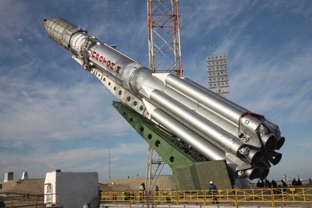
Before the launch at Baikonur
However, by the start of the project there was no engine with the required thrust operating on the data components of the fuel. At this time, the OKB-1, headed by Sergey Korolev, was created PH N-1, is designed for the lunar program. Her in KB-456, under the leadership of V. P. Glushko designed the RD-253. However, for security reasons, and insufficiently high specific impulse of this engine, which uses highly toxic fuel components were not used in the creation of N-1, but its driving performance is good enough for a combat missile UR-500.
The Government decree on the establishment of the UR-500 came out at the end of April 1962 and was assigned to create a missile for three years. In may this year, the CB finally adopted the structural scheme of the carrier, which includes a block layout 1st stage parallel arrangement of the fuel tanks. This design provided the transportation of the rocket from the factory-from-gotovtes at the launch site by rail. This condition limited the length of the rocket blocks of approximately 20 m and a diameter of 4.1 m.
In 1964, it completed the construction of the launch complex at the Baikonur cosmodrome. It established full-scale model of the UR-500, which showed the leaders of the state. During the preparation for flight tests.
However, after the change of leadership of the country, the fate of the UR-500 was not clear. Apparently, this was mainly caused by the changes in military concepts that do not involve the use of heavy duty weapons. It became apparent imminent decision to halt work on a “palisade”. However, at this point, the President of the Academy of Sciences of the USSR M. V. Keldysh who understood the need to create severe PH for space research, fully supported the continuation of work on the UR-500. And thanks to his perseverance, the rocket managed to defend, but not as a war but as a space.
Funds were allocated for the development of a three-stage variant of PH, called UR-500K, which was supposed to use in the works under the lunar program. Crucial to continue work was the first launch of the UR-500, held on 16 July 1965, when the orbit was launched heavy research satellite “proton”. Its name was subsequently transferred to the rocket.
Flight testing two-stage version ended a year later. For him there were three run and brought into orbit of two artificial Earth satellite (AES) weighing of 12.2 T.
In 1968 he launched the artificial satellite “proton-4” weight 17 so This was the first launch of three-stage variant PH, known officially as the “proton-K”.
To a three-stage version went easily enough. It was as follows: in the second stage increased the volume of the fuel tanks, changed the truss design transfer compartment, connecting it with the 1st stage; 3rd stage was formed by shortening the original version of the 2nd stage, it was installed a sustainer liquid rocket engine (LRE) instead of four; management of 1st and 2nd stages were carried out by the swing of the main engines mounted on the hinge brackets, and 3-stage — deviation additional four-chamber steering engine. All boosters of the steps was built on the most advanced scheme with afterburning of the generator gas. It is possible to obtain very high performance for engines operating with high-boiling propellants. Three stages were connected in series, their design is made mostly from aluminum alloys. The separation of the 1st and 2nd stages have been on a “hot” scheme and 2nd and 3rd — “semi-hot”.
So, in a very short time the media was created to fulfill the first phase of the lunar program (lunar flyby). However, PH itself could not ensure the removal of useful cargo on the flight path to the moon. In September 1965, S. P. Korolev submitted several varieties of the UR-500K to complete this task. Was selected using a 4-tier missile blockade, which was created for the rocket-space complex N1-LZ, and a simplified version of the ship LZ, named 7K-L1. This project is called the UR-500K-L1. Within its framework 10 Mar 1967 20 Oct 1970, spent 11 unmanned launches. The results of the flight tests were issued a negative opinion on the reliability of the complex UR-500-L1. The program was discontinued, especially in July 1969, American astronauts visited the moon.
However, four-stage variant of the rocket has been very successful for launches of space vehicles (SPACECRAFT) to the planets of the solar system. It was a space station of a new generation: “Luna-24 14,15…”, “Mars-2…7” and “Venera-9… 16”, “Phobos-1, Phobos-2” and others. With their help, have been resolved important scientific and technical tasks to study the planets of the solar system. In addition, this variant PH was the only national means of launching into geostationary orbit of the satellite type “rainbow”, “Screen” and “Horizon”, providing communication services, and retransmission of television programs. At the same time the three-step option was used to launch all space stations (from “Salyut-1” and ending with “Mir”) as well as the transport of logistics vehicles.
Currently, “proton-K” is used to start blocks of the international space stations and commercial communication satellites. It is one of the most reliable carriers in its class. During the period from the start of testing to April 1998 produced 251 run (in the three-stage version — 28, four-speed — 223). Of them emergency, because of the failure of the media was only 19.
The carrier rocket “proton-K”:
1 — fairing; 2 — antenna; 3 — cylindrical adapter unit D; 4 — tapered adapter unit D; 5 — instrument compartment 3 tier-PH; 6th — PH telemetry antenna; 7 — fuel Bay 3 tier-PH; 8 — the tail section of the 3rd stage; 9 — braking solid rocket 3rd stage; 10 — transitional compartment; 11 — brake solid-propellant 2nd stage; 12 — cell 2nd stage; 13 — skirt; 14 — propulsion system 2nd stage (RD-0210 and RD-0211); 15 — farm 2-th stage; a 16 — screen; 17 — farm 1st stage; 18 — upper head of the Central unit 1st stage; 19 — spacer; 20 — front compartment side of the block; 21 — oxidizer tank; 22 — fuel tank; 23 — the rear compartment Central unit; 24 — spars and plate; 25 — starting bearing; 26 — the rear compartment of the side block; 27 — RD-253; 28 — tie; 29 — autostick; 30—RD-0214; 31 — the fairing head unit; 32 — fairing fuel; 33 — fairing oxidizer 34 — fairing;
The first stage PH U R-500K consists of a Central block (CB) and located symmetrically around it six mounted units. The Central unit includes a transition compartment, oxidizer tank and tail section. In turn, the transitional compartment consists of farm and spacers. Farm connects 1st stage with the 2nd and provides free exit of gases when starting the engine of the 2nd stage. It is formed by a steel frame of channel section and the crosspieces, fastened to it by bolts. Each cross is made of two steel struts. The lower ends of the crosspieces are connected by bolts to the top frame spacers with riveted construction. Its bottom frame flange joint it is attached to the tank oxidizer.
Oxidizer tank is a welded, supporting structure. It consists of cylindrical shell, reinforced frames, and two spherical heads. Inside it are mounted six longitudinal damping partitions for damping oscillations of the oxidant, the systems of simultaneous emptying tanks (SOB) and monitoring stations (RMS). Top and bottom mounted atomizer gas pressurization of the tank and drain-relief valve. In addition, the tank has a manhole for access into the manufacture and installation of systems. Outside the bottom of the closed heat shield out of foam and fiberglass. On the bottom the bottom there is a flange for fixing the expenditure of the pipelines (going to each engine), highways filling and draining of the oxidizer.
Tail section — conical shape, riveted construction. It consists of frames and plating, which externally reinforced with longitudinal stringers. In addition, there are 12 longitudinal side members, perceiving traction engines and the load from the starting poles. The side walls are mutually connected plates, each with openings for filling and drainage of the neck. On the lower ends of the plates located starting support for installation and fixing of the rocket on the launcher. Inside the compartment there is a valve for piping, and at its lower end, a closed heat shield, mounted autostick. Through automatic docking gas communications, pneumatic and electrical connectors all of the steps to launch complex. At startup after undocking connection speed missiles, autostick closed by special covers. The piping pneumatic-hydraulic system and a cable network laid outside the Bank and closed three garrote: in the third control plane is the fairing headunit, left fairing oxidizer, and the right side — fuel.
Side blocks (BB) are identical in construction and each consists of a front compartment, fuel tank and tail section, which is fixed to the engine. The front compartment, riveted construction, has a conical shape and serves as an aerodynamic fairing of BB. There are hatches for the installation and maintenance of equipment. The upper part of the compartment is made removable. The outside is covered with insulating materials. Fuel tank is welded, consists of a smooth cylindrical shell section design, heavy frames, and two spherical heads. Inside it is equipped with sensors GSS and RMS, and four longitudinal damping partition. Tail section — riveted construction. His body form the frames, a set of stringers, two slabs that serve as the base for steel traverse motor mounts, and plating. The outside compartment is closed heat shield, which protects communications and units of the engine from heat when it is working.
The side blocks are attached to the Central five zones. The two lower have a fixed connection, the other is movable. One of them is a bolt connection of the extreme of the traverse engine mount with two spars of the tail section of the Central Bank. The second zone is at the top of the tail section of BB. It is formed by 12 nodes consisting of lugs on the tail section of the Central Bank of fangs, the tail section of BB. Fangs are included in the eyelets from the bottom (direction of thrust) and fixed with bolts. Each Fang thrust force of engine is transmitted from traverse his suspension through the corresponding plate, and lugs attached to the power to frame the tail section of the Central Bank.
The rest of the belt have a connection type “thorn-groove”, allowing longitudinal movement and thrust, locking the BB in the radial direction. They perceive lateral force. Two such belt fasten tanks of fuel and oxidizer tank, and the third connects the upper part of the front compartment of BB with the upper bulkhead of the oxidizer tank. Between the BB in the area caudal compartments located fairings, designed to reduce the aerodynamic impact on the engine by their rejection.
The propulsion system of the 1st stage consists of six independent propulsion rocket engine RD-253, developed by NPO “Energomash”. For thrust vector control engines suspended on bearings traverse in the area of the critical section and can deviate by up to 7.5 degrees by using a hydraulic drive. Earth engine thrust of 150 tons, specific impulse — 280, the pressure in the combustion chamber to 150 atmospheres.
The second stage cylindrical shape. It consists of a transition, the fuel and the tail section. The transitional compartment — riveted construction, connects the 2nd level with the 3rd. Its body is constituted by frames, stringers and plating. In the upper part of the housing are four channels for the exhaust gases when you start the steering engine 3-tier and the lower part are six braking rocket engine solid fuel (SRM) breeding stages, closed fairing.
The fuel compartment is a single unit of tanks of fuel and oxidizer separated by an intermediate bottom. Shell tank smooth, welded from three sections, and the shell of the oxidizer tank consists of four sections of waffle design, made by mechanical milling. All the bottoms of the spherical shape, welded to the shells butt with frames. Inside tank of fuel is a consumable oxidizer tubing, and inside the two tanks installed sensors systems GSS and CPS.
The rear compartment consists of a housing (skirt), power cone and a protective screen. The skirt is joined by two parts — upper and lower. Upper — riveted construction consists of a set of stringers, frames and plating. The lower part is a farm, similar design as the farm transition compartment 1-th level, with one difference — no ring frames. Crosses the lower part of the skirt connected to the frame farm 1st stage centering pins and explosive bolts. Power cone riveted construction used for fastening the motor to the farm, and transfer thrust propulsion rocket engine to the fuel compartment. The cone consists of plating, frames and stringers are located outside of the plating.
Propulsion system 2nd stage form four similar and Autonomous rocket engines: three RD-0210 and one РД0211. They developed in kbkha in Voronezh under the leadership of S. A. Kosberg. For flight control, as in the 1st stage, they could deviate with the help of hydraulic actuator up to 15 degrees. The thrust of each rocket engine is 58 tons, specific impulse 326 S. On the outer surface of the 2nd stage padded, closed three gargrota, pneumatic-communication and cable network. Their purpose and location similar to gargrota 1st stage. The engines of the 2nd stage run before the start off the engines of the 1st stage. As soon as their desire exceeds the residual engine thrust 2nd stage, there is a rupture of the explosive bolts connecting the farm gears, and the jet engine 2nd stage brake and push the 1st tier.
The third stage of cylindrical shape. It consists of an instrument, fuel and the tail section. Instrument compartment riveted construction is constituted by frames, stringers and plating. In it are mounted the devices, systems, control, stabilization and aiming. Access to them through hatches.
The fuel compartment is structurally similar compartment 2nd stage. The difference lies in the fact that its oxidizer tank has shells. He’s educated middle and lower dniami, United welding on frames, which gives it a lenticular shape. Sides of the fuel tank is welded from two sections of the waffle design. The bottom the bottom is cone-shaped and perceives stress thrust rocket engine attached to it. In the upper part of the oxidizer tank mounted horizontal damping partition, and inside the fuel tank is mounted sloping consumable pipeline oxidant. In both tanks mounted sensors and the RMS levels of SOB.
Tail section — riveted construction serves to accommodate four-chamber steering engine and brake mounting four solid propellant motors. Its body consists of skin, two connecting frames and stringers. To the caudal compartment by means of centring pins, and explosive bolts fit in the 2nd stage. Pneumatic and hydraulic communication stage are in three gargrota, similar to the 1st and 2nd steps.
Propulsion system (PS) of the 3rd stage consists of the sustainer rocket engine RD-0212 and steering engine RD-0214. Sustainer rocket engine is a modification of the rocket engine 2nd stage. The four chambers of the steering liquid rocket engines can be deflected by the actuator to 45 degrees, providing control and stabilization. The separation of the 2nd and 3rd stages is due to the thrust of the steering engine 3-tier that run off at the sustainer rocket engine 2nd stage and braking it located on it SRM. At the end of the active portion of sustainer rocket engine of the 3rd stage switches off and only works the steering engine. This principle allows you to more accurately achieve the desired end speed. The separation of the payload is performed after turning off of the steering expander and subsequent inclusion of the four brake SRM.
If PH is used in a three-stage variant, the payload is attached thereto via a transition compartment. He docked with the upper frame of the instrument compartment of the 3rd stage in aid of the centering pins and of explosive bolts, blowing which is separated payload.
The head unit (it consists of the booster unit D, the payload and the corresponding fairing) when using four-directebanking option is attached through cylindrical and conical adapter booster. Conical adapter with centering pins and bolts connected with the upper frame of the instrument compartment 3-tier. The separation of the upper stage 3 stage occurs at the junction of the cylindrical and conical adapter booster. In this case the conical adapter stays together with the 3rd degree. Fairing is reset to its initial period of operation of the 2nd stage.
The carrier rocket “proton-K”
The basis for the design of the booster unit D and its modifications DM, which is characterized by the presence of the Autonomous management system, is libacovea compartment of conical shape, located a large base up. It is the reference frame used for mounting the head fairing, the payload of the farm through which is attached to the instrument compartment of the Autonomous control system (block DM) and the block to the cylindrical adapter. In the compartment is mounted a spherical oxidizer tank (liquid oxygen), and in the lower part of the farm that is attached toroidal tank of fuel (kerosene). Sustainer rocket engine RD-58M (draft 0.86 t) is mounted on a gimbal in the inner layer farm in the Central hole of the torus tank. Such layout allowed to reduce the length of the unit and to control the flight at the rate and pitch deviation of the engine, and roll the special rotary nozzle using the exhaust of the turbopump unit. Also the unit comes with a multiple device launch, providing up to seven inclusions LRE.
Currently Khrunichev im. M. V. Khrunichev, works on modernization of the PH “proton-K”. Upgraded carrier received the name “proton-M”. It is supposed to increase the mass of payload output from the base orbit to 22 tons, into geostationary — up to 3 T. This is achieved by forcing all propulsion rocket engine and the installation of more perfect management system. Develop new upper stage “Fregat” and the fairings with a diameter of 5 m for KA large size.
V. MINAKOV, engineer
Literature
1. “News of cosmonautics”. No. 10, 1998, p. 27.
2. Putnicki Yu. V., etc. Domestic boosters. —SPb., Ed. center gmtu, 1996.
3. Rocket and space Corporation Energia after S. P. Korolev. Under the editorship of Yu. p. Semenov. — Publishing house RKK Energiya, 1996.
4. S. P. Korolev and his cause. Light and shadow in the history of Astronautics (Selected works and documents). Under the editorship of B. V. Rauschenbach. — M., Nauka, 1998.
5. Umansky, S. P. boosters. Spaceports. — M., “Restart Plus”, 2001.
6. Filin V. M. and others Rocket and space Corporation Energia after S. P. Korolev. — Publishing house of RSC Energia, 1994.
Recommend to read SUPPORT CLAY Medical bubbles, and especially the opened vial is very fragile, and spill their contents sometimes very simple. To avoid this, use a "tortilla" of clay: recessed in her glass bottoms of... ELECTRONIC “MATCH” They say you can't save much on matches, and yet... A simple and practical electronic "match," the description of which we offer to readers' attention, will free you from the need to...
Scroll back to top
 This slogan was the basis of the life and work of one of the founders of Russian space engineer Friedrich Arturovich Tsander, who developed the 20-ies of the last century one of the first projects of the spacecraft for flight to Mars. However, he was not only a dreamer — in the early 30-ies took an active part in the development of the first domestic liquid-propellant rocket engines and rockets in the famous gird.