“Manual labor — to the shoulders of machines!” — under this headline, materials from the All-Union Conference of VISKHOM named after V. P. Goryachkin were published in our magazine (see “M-K”, 1982, No. 8). With the speeches of its participants about the importance and necessity of developing small-scale mechanization means, the editorial board opened a correspondence “round table”, and at the same time we invited readers to send drawings and diagrams of their machines and asked them to share their experience of building, manufacturing, and operating them.
We give the floor to Viktor Alekseevich Chirkov, an amateur designer from the Moscow region town of Lotoshino. He has already accumulated considerable experience in creating small-scale mechanization means and today introduces readers to his latest development — the MT-5 mini-tractor. It seems that novice designers will find useful some considerations of V. A. Chirkov about designing and assembling such machines, using serial units and parts in them.
CHOOSING A TRACTOR
In the Non-Black Earth Zone of Russia with its difficult-to-work soils, the use of a mini-tractor seriously increases the productivity of the farmer. In many villages of our district, motoblocks and baby tractors assembled by enthusiasts work annually on household plots. But often their builders find it difficult to answer the question: why did they settle on this or that scheme of their tractor? Here, in my opinion, one should start from what purposes the future machine is intended for and how many people will use it.
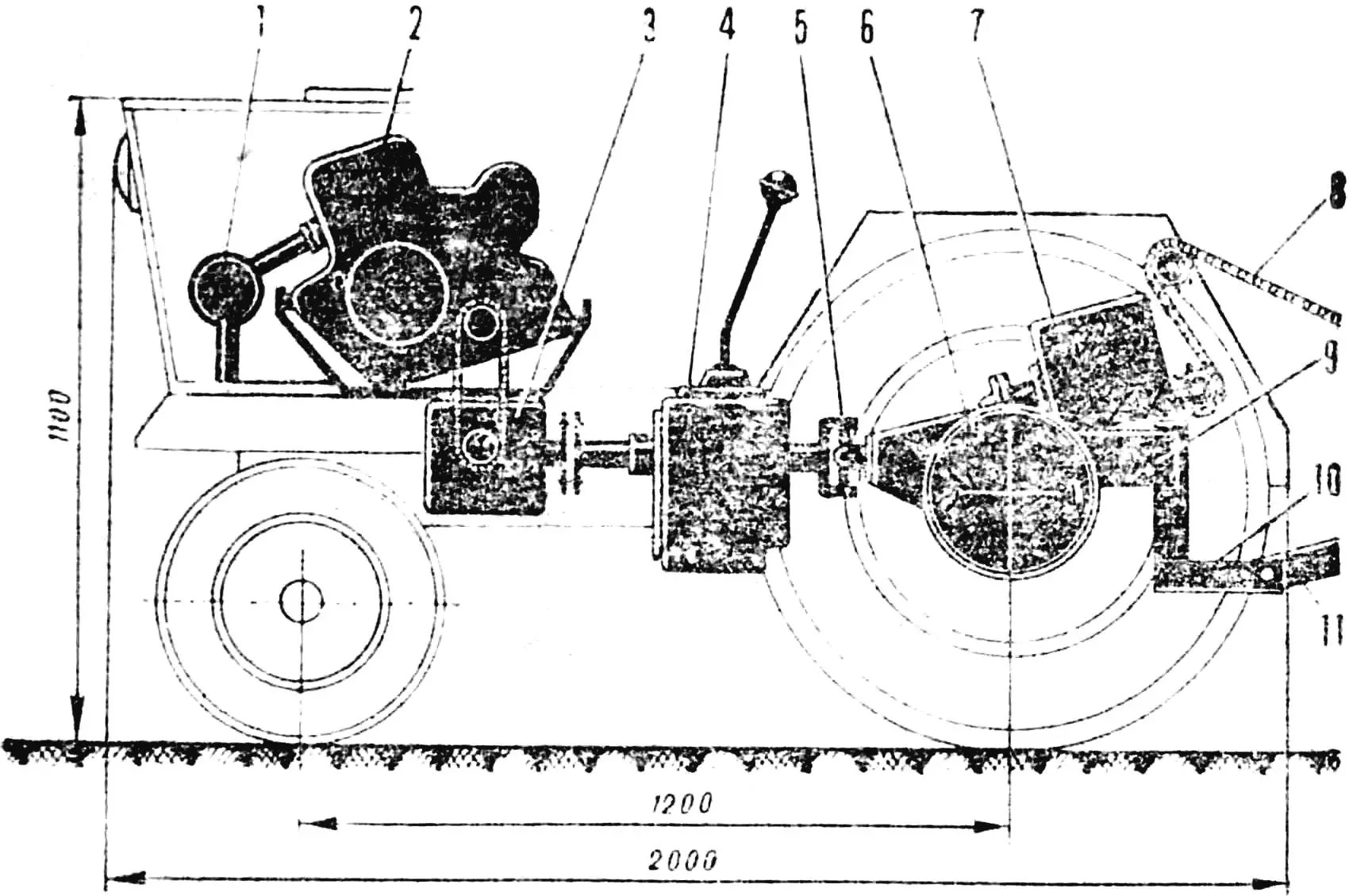
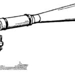
1 — muffler, 2 — engine, 3 — angular reducer, 4 — gearbox, 5 — cardan joint, 6 — rear axle, 7 — implement control reducer, 8 — implement lift chain, 9 — tractor frame, 10 — subframe, 11 — agricultural implement frame.
For individual use, one should design motoblocks — single- or two-wheeled with engines from “Vyatka”, “Tula-200” or motorcycle engines of the same power with forced air cooling, say, taken from the SZA motorized wheelchair.
A mini-tractor is more of a collective means of soil cultivation. It is preferable to assemble it from the most common automotive and motorcycle units and parts. The engine power here needs to be greater than that of motoblocks: Izh engines, from K-750, will do. The difficulty of cooling such an engine is overcome by installing a water pump or a pump with the simultaneous use of an automotive fan. Such an agricultural unit will provide prompt processing of several plots. Low-power homemade tractors of the “Vladimirets” type are also not out of the question. This will already be a public-use tractor — for a gardening cooperative.
ORIENTATION — ON SERIAL UNITS
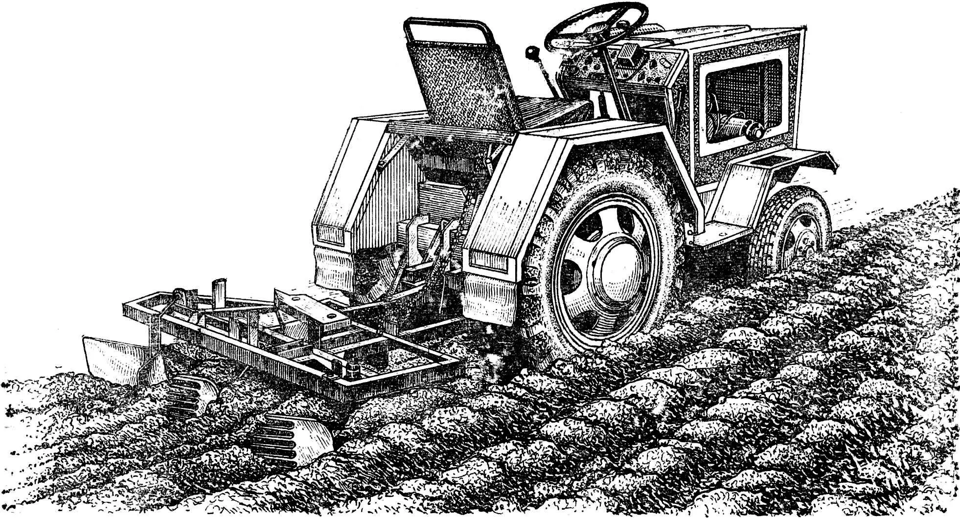
My MT-5 fits the second such type. MT means mini-tractor, and 5 indicates that this is already the fifth model, so much in it, as they say, has been brought to condition. It is assembled mainly from units and assemblies produced by industry. I tried to arrange it so that access to all units and assemblies would not be difficult, of course, with the provision of safety requirements: all rotating mechanisms are closed with easily removable covers and panels.
I installed an engine from IZH-56 P with an “air blower” for cooling from the SZA motorized wheelchair (I didn’t have a water cooling system then). The rear axle is from “Volga”, only shortened. The gearbox is from GAZ-51. The steering column and seat are from UAZ. There are two reducers. One with a ratio of 1.3:1 had to be installed to change the direction of force transmission from the engine to the gearbox at an angle of 90°. The other — with a ratio of 15:1 — for controlling mounted agricultural implements: lifting, lowering using a chain drive.
The front axle is homemade, made of water pipes, of the “swinging pendulum” type, like on wheeled tractors, and the fenders, hood, and frame for mounted implements are made of metal angles and sheet scraps. The front wheels with hubs and tires are taken from SZA, the rear ones — from MTZ-52 (its front ones).
The MT-5 has the necessary set of forward and reverse gears and neutral. Speed from 0.5 to 40 km/h. Track width 0.9 m with expansion if necessary (for example, for hilling potatoes) to 1.3 m.
ASSEMBLY: ORDER IN REVERSE
Amateur builders often complain about the troubles that assembling structures causes them, meaning numerous modifications and alterations. Most try to copy someone’s samples. However, it is more rational to focus on the chosen system, and use the parts that are available. The work will go both faster and cheaper — you will only have to purchase the necessary minimum, and, importantly, there remains room for creativity.
Assembly usually starts with the frame, front end, engine installation, etc. I, however, advise starting with the rear axle first. You need to put all its parts in place, connect it to the gearbox, fasten the flanges. Before tightening the mounting bolts, turn the gears several times, adjust their free play, and also make sure that the gearbox is installed without distortion — strictly along an imaginary center line passing through the connecting parts of the tractor.
Let’s connect the reducer or the engine itself to them. Let’s do this, as they say, “in the air” — on supports, positioning them so that all units are in the same horizontal plane. Having achieved the absence of shaft runout, we will fasten the bolts on the connecting couplings and flanges. It remains to decide where the front axle will be located, how it will be attached to the frame, and install it in the intended place.
Now proceed to the operation that is usually done first — marking the frame (chassis), but already “in the open”, “in place”, and to its manufacture. A different assembly usually leads to “drift” of mounting locations, to “failure” of dimensions, which entails repeated movement of units.
When you have already installed the power and running units on the frame, it is necessary to test the entire structure. Let the engine run idle for some time, for which lift the rear wheels above the ground on trestles.
Finally, mark the locations, and then secure the steering control units and parts, engine and gearbox control, clutch, protective covers, fenders, hood, seats.
I have repeatedly recommended this assembly order to amateur designers who turned to me — their feedback has always been positive.
HOW TO MOUNT A PLOW
Another typical difficulty is failures with installing agricultural implements on the tractor. In my opinion, the reason often lies in not quite the right choice of the location of the hitch device. For example, where should the plow be located? After all, plowing, as is known, is an operation that requires the engine to deliver high power. If the plow is shifted more than necessary toward some wheel or is located behind it, the hitch will begin to drift toward that wheel. And two or three plows, which, with their appropriate arrangement, could bring the acting forces into some balance, the mini-tractor will not pull.
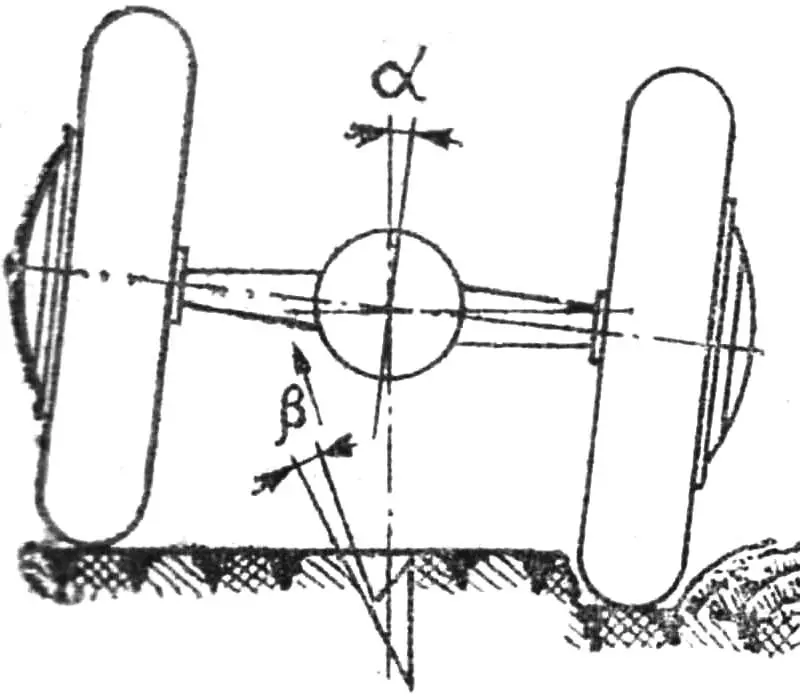
α — installation angle due to MT-5 roll, β — share tip rotation angle.
The solution is as follows. First, reduce the track width to 90 — 100 cm — this is the maximum for plowing. Second, shift the plow mounting toward the center so that the wheels on its side run in the furrow. The tractor in this case acquires a certain angle of inclination. For example, on the MT-5, the right wheels are in the furrow. Therefore, before plowing, I install the plow with the same deviation from the vertical to the right, so that during operation it takes a vertical position. Accordingly, its share tip in this case must be turned 1—2°, but already to the left. Then the “resistance” of the earth will take up all the gaps, turn the machine back (again to the right) and the implement will be in the longitudinal plane of the tractor. Third, the need to maintain a certain ratio between the distance from the tractor subframe of the mounted plow installed on the frame and the height of the subframe and frame connection point above the ground has been identified. It should be no less than 3:4, otherwise the plow spontaneously jumps out — rises from the furrow without penetrating the soil. On the MT-5, this led to the frame length exceeding a meter, and the height of the connection point above the ground, on the contrary, decreased to 30 cm.
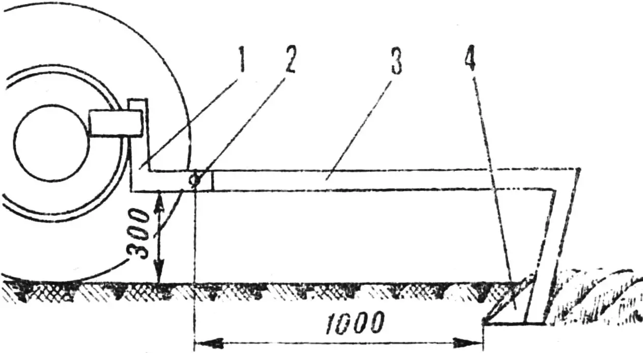
1 — tractor subframe, 2 — connection point, 3 — plow frame, 4 — plow.
A few more words about the rational use of a mini-tractor with various agricultural implements. When growing, for example, potatoes in the spring, I perform plowing of the plot with simultaneous harrowing of the soil using the MT-5. The harrow is hung on a special bracket on chains immediately behind the plow and can be lifted simultaneously with it. Since the right wheels of the tractor run along the previously made furrow and take part of the plowing behind the right rear wheel, I also install a sweep cultivator for repeated partial loosening of the “damaged” strip. I make the bed cuts with three hillers at once. On the next pass, one of them is already used as a guide. During this operation, a cultivator has to be placed behind the rear wheel again. I plant potatoes, if I may say so, “in a semi-mechanical mode”, that is, the tubers are placed manually in the furrow made by the outer hiller, and on the next pass it is covered with earth from both sides by two others, and the outer one again leads — opens a new furrow.
I also hill the beds with three tools at once, and I increase the MT-5 track width to 130 cm and the wheels run between the beds (the distance between them in my garden is 65 cm). I dig up the harvest with a horse plow — right-hand moldboard, so I start work from the left side of the plot from the leftmost bed, moving the earth and exposed tubers to the right onto the still untouched neighboring bed. This has its advantages: when harvesting potatoes, it is easier to dump the earth from top to bottom, back into the just-made furrow. At the same time, the garden is leveled.
«M-K» 2’83, V. CHIRKOV
Recommend to read
 PIPE RESONANCE
In the magazine we told about the methods of choosing the parameters of the resonant pipes ("modelist-Konstruktor" No. 9 for 1995) for highly accelerated engines. Fulfilling the wishes... SIGHT – CHAMPIONSHIP
The magazine "M-K" in the last few years has published a number of interesting patterns with rubber motor, with an unusual decision nodes, and technological methods of their creation....
