Motorists know that cars sometimes suffer breakdowns that make towing them on a rope either prohibited (steering or braking system failures) or impossible (certain transmission or running gear damages).
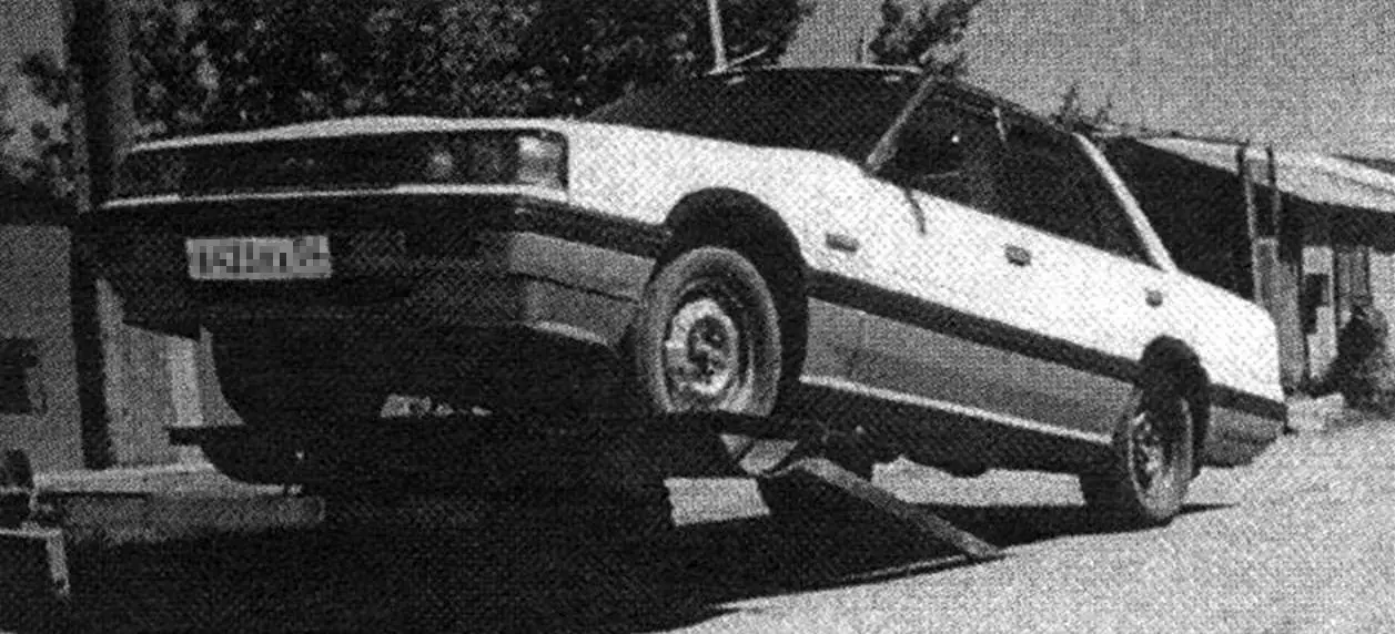
For such cases I made a tow dolly. The broken car is loaded onto it partially — only the front or rear axle is rolled up. Any passenger car can be placed on the dolly and transported at speeds up to 30 km/h.
The dolly frame is rectangular, measuring 700×600 mm. Its longitudinal beams (side members) and the “rays” of the triangular drawbar are made from steel channel No. 6.5, 65x36x4.4 mm, with parallel inner faces of the flanges. The joints of these parts are reinforced above and below with 6‑mm steel plates welded on. The frame crossmembers (traverses) are made of channel No. 5 (they fit between the flanges of the side members). At the junction point of the drawbar “rays” I welded to their end a 10‑mm steel plate 70×70 mm with a central hole 28 mm in diameter for the shank of the ring‑type hitch.
I chose a ring‑type hitch because, according to traffic regulations, the towing vehicle must have a load capacity at least 1.5 times greater than that of the towed car. Such vehicles are usually equipped with a towbar or a special towing eye.
The shank and the ring were made from a single piece of 27‑mm steel bar about 550 mm long. One end of the shank was turned down to 24 mm over a length of 40 mm and threaded. The other end was heated halfway in a forge, bent into a ring on a 65‑mm mandrel and welded. A 10‑mm thick steel washer with an outside diameter of 50 mm was slipped onto the shank tight against the ring and welded on.

1 — ring with shank (steel, Ø27 bar); 2 — front plate (steel, sheet s10); 3 — thrust plate (steel, sheet s10); 4 — spring (Ø44×8, L70); 5 — M24 castellated nut; 6 — winch (i = 40); 7 — drawbar (channel No. 6.5); 8 — frame side member (channel No. 6.5); 9 — vertical posts (channel No. 12); 10 — disc (steel, sheet s6); 11 — turntable unit (split rim of a ZIL‑130 wheel); 12 — rotating platform (steel, sheet s6); 13 — ramp (channel No. 12, L1500, 2 pcs.); 14 — traverse (channel No. 5, 2 pcs.); 15 — U‑bolt from a Moskvich‑412 spring, 2 pcs.; 16 — axle with wheelset; 17 — upper platform (steel, sheet s6); 18 — inner stop (steel, Ø20 bar, 2 pcs.); 19 — outer stop (steel, 50×50 angle, 2 pcs.); 20 — wheel cradle (steel, sheet s6, 2 pcs.); 21 — connecting pin (steel, Ø24 bar, 2 pcs.); 22 — hinge lugs (steel, 34×4 tube, 4 pcs.); 23,24 — rear and front beams (channel No. 6.5); 25 — ring (“sliding bearing”)
The towing hitch is spring‑damped. It is equipped with a damping unit with a normally stretched spring with an inner diameter of 28 mm, wound from 8‑mm wire. The spring on the shank is slightly compressed between a thrust plate welded inside the drawbar channels and a stop washer with a cottered M24 nut. The thrust plate was first made from a cardboard template cut to fit in place.
On the sides of the front part of the drawbar I welded brackets for safety chains, and on top — a steel plate with holes for mounting the winch.
To the side members, through holes drilled in their flanges, I attached with U‑bolts from a Moskvich spring a tubular axle about 1 m long with a pair of wheels. To prevent axle deformation, I placed steel shims between the axle and the side members and tack‑welded them to the U‑bolts. Next to them I welded additional stops to prevent lateral axle shift.
At first I mounted decommissioned helicopter wheels on the dolly — they suited it perfectly, but later, unfortunately, were lost. I had to adapt wheels from an agricultural stubble cultivator, although this significantly increased the dolly height because of the large tire diameter.
On the frame I installed a load platform consisting of a turntable unit and two transverse cantilever beams with wheel cradles between them for the wheels of the towed car.
Assembly of the platform had to start with installing on the frame a pair of tall transverse pads made of channel No. 12, which increased the car loading height. This was undesirable but necessary to ensure the platform could turn without the cradles touching the dolly wheels.
I made the turntable from a split rim of a ZIL‑130 truck wheel (the rim consisted of a bead ring and a split wedge ring‑flange). For this I set the flange ring horizontally on low blocks with the sharp edge upward, slightly widened the split and fitted the bead ring onto it. From 10‑mm smooth steel bar I bent a ring (“sliding bearing”) and welded it with a continuous seam to the flange. The sharp edge of the flange protruding above the ring was cut off with an oxy‑fuel torch. Then, from 6‑mm sheet steel, I cut a disc to the outer diameter of the ring and welded them together around the entire circumference. After turning the assembly over, I set the disc on the crossmembers and welded it too. On top of the bead ring I welded a rotating platform 620×620 mm made of the same 6‑mm sheet. (Before each tow, the rubbing surfaces of the turntable were lubricated with used engine oil.)
On the rotating platform I mounted two transverse cantilever beams 1800 mm long made of channel No. 6.5 (this size includes the distance between the outer sidewalls of the tires of a Volga car). The rear beam was installed with the flanges facing down to reduce the loading height of the broken car, and the front beam was set on its side, on the flange. The clear distance between the beams is 480 mm. Their ends are connected by 50×50 angle sections that act as outer stops. The inner stops are made of 20‑mm steel bar, spaced so that the front wheels of a Zaporozhets car can fit between them.
Between the outer and inner stops I welded wheel cradles made of 6‑mm sheet steel, first curved on rollers to match the outer diameter of Volga tires.

To load the broken car onto the dolly I made from channel No. 12 two ramps 1500 mm long (practice has shown that it is better to make them from channel No. 16 or even No. 18 and install them with the flanges facing up, using them as wheel troughs). The rear ends of the ramps were cut on a bevel, and the front ends were hinged to the channel of the load platform. The hinge lugs are made from pieces of 34×4‑mm tube. The hinge pins are made from 24‑mm steel bar. One end of each pin is bent and serves as a handle‑stop, the other is drilled for a cotter pin. The ramps can move along the pin within the width of the cradle to match the track width of the broken car. During transport the ramps are bolted to the “rays” of the drawbar, for which matching holes are drilled in both.
To pull the broken car onto the dolly I mounted on the drawbar a winch from a panel truck with a gear ratio of 40:1. The winch cable is a 10‑mm steel rope 5 m long with a hook at the end. During transport I keep the hook engaged (for safety), slightly slackening the cable.
“Modelist‑Konstruktor” No. 10’2001, V. Baranov, Novosibirsk
A motorcycle and a car are different machines. First and foremost, in terms of comfort. But can the advantages of two-wheeled transport be combined with the convenience of a passenger car? It turns out they can. Such two-wheeled machines—autorollers or motocars—are sometimes seen on the streets. We suggest you build one of these designs yourself.
This vehicle is a scooter with an engine of about 50 cm³ displacement, which, unlike traditional two-wheelers, has a light plastic body with a folding top, a seat almost like in a car, and two additional small wheels that can be raised and lowered like landing gear on an aircraft.
Let’s get to work. We’ll start with the frame. Obviously, you can’t build it without a welding set. You’ll need steel tubes with an outside diameter of 34 mm and wall thickness of 2.5 mm, tubes 22 mm in diameter (same wall thickness), and a front telescopic fork from any moped or scooter. The frame is designed for wheels from a Riga-built mini-moped, but scooter wheels will work too. You’ll also need sheet steel about 2.5 mm thick.
First, draw the frame full size. This will let you cut the blanks correctly and accurately from the drawing and finally fix the main dimensions of the parts.
As the drawings show, the autoroller frame is backbone-type and consists of a welded two-tube L-shaped spine that also acts as the rear wheel fork. To each tube, 4 mm thick steel plates with longitudinal slots for the axle are welded. We recommend cutting the slots after the plates are fitted—this helps get the work more accurate.
Now join the rear wheel to the frame tubes, tighten the axle nuts firmly, and mark where the bends will be. For a small bend you don’t need to pack the tube with sand—a tube bender is enough. After fitting, the tubes are welded at two or three points.
Next, fit the wheel in the front fork and fix the fork to the floor with wooden battens in the position shown. In the same way, set the frame spine with the rear wheel. Temporarily secure the spine to the steering column with soft copper wire. Check the wheel alignment carefully—they must lie in one plane. If correct, tack the spine to the steering column in two or three places. After final fitting, weld all joints fully. At the front, the spine-to-column joint is reinforced with gussets cut from 2.5 mm steel sheet.
The rear engine mounting bracket is cut and bent from 3 mm sheet steel. Do this in place: first cut a cardboard template and only after fitting make the metal blank. Fit the front bracket the same way.
After machining, attach the bracket to the engine and fix it on the frame with wire. Alignment must be checked again—the cylinder axis must lie in the frame’s plane of symmetry, and the carburetor platform must be level. After tacking the brackets, do a final check and complete the welding with the engine removed.
The frame base is ready. Add the cross tube that serves as the pivot for the extra wheels and small pads for the driver’s seat. The frame is then fully assembled.
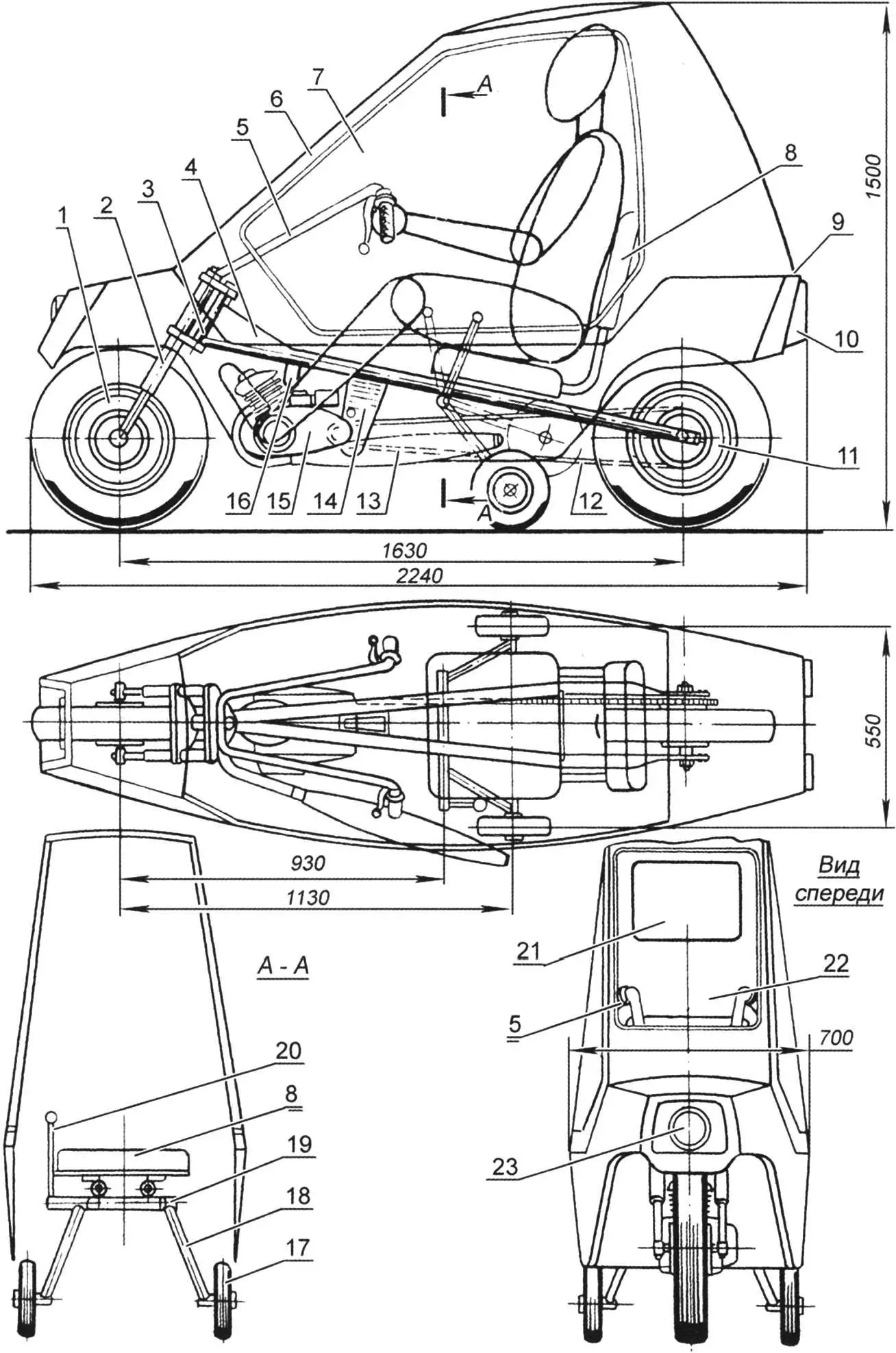
1 – front wheel (from mini-moped or scooter); 2 – front wheel fork (from any moped); 3 – frame steering column; 4 – reinforcing gusset from 2.5 mm steel sheet; 5 – handlebar (from mini-moped); 6 – folding glazed cab – “canopy”; 7 – block “glass” (Mylar film); 8 – driver’s seat (metal chair top, padded with foam and vinyl); 9 – hinge of folding cab (“canopy”); 10 – rear lights and stop lights (from motorcycle or scooter); 11 – rear wheel (from mini-moped or scooter); 12 – bushed roller chain (from two standard moped chains); 13 – muffler (from any moped); 14 – rear engine bracket (bent from 3 mm steel sheet); 15 – engine (Sh-58 or Sh-62 type); 16 – front engine bracket (bent from 3 mm steel strip); 17 – side support wheel; 18 – chassis strut (22 mm tube); 19 – support wheel pivot; 20 – chassis wheel raise/lower lever; 21 – rear window (Mylar film); 22 – front window (Mylar film); 23 – front headlight (from any moped)
For the extra wheels’ axle, choose a tube whose outside diameter allows it to rotate freely in the pivot. If you can’t find one, use a smaller tube or rod and compensate the gap with rings cut from plastic hose—they work well as plain bearings.
The chassis strut is made from 22 mm outside diameter steel tube. Weld a bushing to one end and a turned steel axle to the other. On the left strut, weld a short 10 mm steel rod with a thread for a plastic handle. This is the chassis control lever.
The extra wheels must lock reliably in both extended and retracted positions. The mechanism is straightforward; we suggest designing it yourself.
Chassis wheels can be from a children’s bicycle. Prefer rubber “balloon” or solid-rubber (not plastic) tires up to 200 mm in diameter.
The autoroller fuel tank is a 5 litre plastic or aluminium can. Fit a standard motorcycle fuel tap with sediment bowl and mount it at the rear of the body. Drill a vent hole in the can cap.
The body is plastic. The structure is built from 20×20 mm wooden battens.
The lower part of the body is like a small boat hull. Assemble the transverse frames from battens, then add the longitudinal battens per the drawing. Then skin the frame. Kitchen furniture plastic (sold in hardware stores) is a good option. Use epoxy for gluing the frame and skin. If you can’t find plastic, thin plywood or hardboard up to 3 mm is acceptable, or other options.
The upper part is built similarly. Glazing is transparent film of the kind used for model aircraft. Make window frames from 10×20 mm battens with spacers. Place the frame on the film, cut with a 20 mm margin, fold the film over and glue to the frame with BF-2 adhesive. Iron the joint with the iron set to “silk”. Then screw the frame into the window opening.
The window may not look perfect at first—Mylar is stiff and hard to tension. Use the iron set to “cotton” or “linen” and iron the film; it will tighten and flatten.
Final finishing is simple. With plastic skin, fill joints with epoxy filler (epoxy glue and talc) and paint with nitro primer then nitro enamel. With plywood or hardboard, level with filler, then cover with a layer of glass cloth and epoxy and paint.
Pay special attention to the controls. They are much like a moped’s. On the handlebar (from a Riga mini-moped) fit the throttle, front brake lever (right), and clutch lever (left). If the engine has a manual gear selector, mount it on the left of the handlebar.
The engine starter needs modification. At minimum, reposition the kickstarter lever on the splined shaft so it’s easy to kick from the seat. Better is a cord starter: fit a pulley on the splined shaft with two or three turns of nylon cord, run the free end to a convenient spot for a left-hand pull, and add a T-handle.
The last control is the chassis raise/lower lever—best under the driver’s left hand. The brake pedal for the rear wheel goes under the right foot.
For the first runs, leave the cab (“canopy”) off. Sit comfortably (chassis extended), put the gear in neutral, and start the engine. After warm-up, move off in first, then second. Retract the chassis only when the autoroller feels stable. Operating the extra wheels will feel odd at first but is easy to learn.
When using the autoroller, remember the engine runs cooler than on a moped. Ensure the cylinder cooling opening in the body is in the front wheel well, directly opposite the cylinder, and larger than the cylinder. If cooling is insufficient and the engine overheats, consider forced cooling. It’s not hard: remove the right crankcase cover and fix aluminium blades for a centrifugal fan on the flywheel/generator rotor. Make an air duct from bent aluminium sheet or from cloth and epoxy on a foam former, filled with plasticine or non-hardening putty.
«Modelist-Konstruktor» No. 6’2014, I. YEVSTRATOV, engineer
Recommend to read
 SHOULDER TIE
In the closet or the wardrobe of any design there are shelves or brackets, hangers for placement and headwear, and outerwear, and shirts. But ties — no special device, except that the... JUMPING IN THE SKY
In the late 1960-ies started to combat service in the Mediterranean and in the Atlantic, the new classes of ships of the Soviet Navy — anti-submarine cruiser "Moskva" and "Leningrad". To...
