Research by scientists and beekeepers’ experience show that with adequate quality feed and careful management, flying honey producers tolerate wintering well even in severe frost. For a weakened bee colony in cold weather, the trouble is less the low temperature than high humidity, when frames and the inner surfaces of hives grow mold, and the increased thermal conductivity of humid air around the bee cluster and damp walls threatens greater heat loss — with all the heavy consequences that follow.
Measures I have applied for several years involving electric heating in winter allow comfortable conditions to be created and maintained, preserving bee colonies of any strength. In essence, this is a system of convective hive ventilation (SKVU — the term is supported by the national patent office). I am glad to share my developments with readers of Modelist-Konstruktor, among whom (see Nos. 5’73, 6’81, 12’87, 12’92, 10’93, 12’95, 12’96, 5’97, 6’97 and 10’97 of the journal) there are many keen beekeeping enthusiasts.
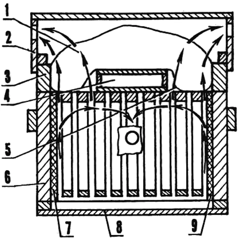
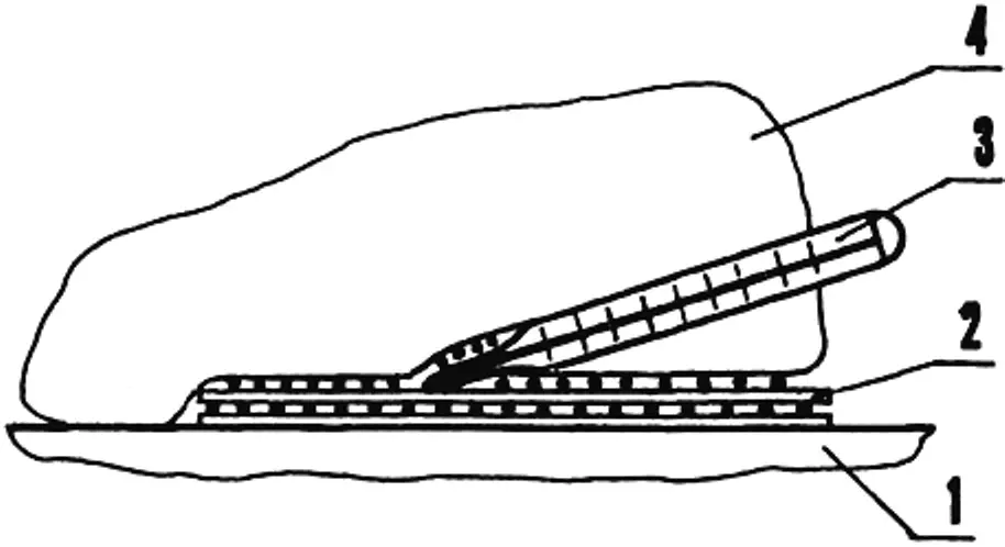
1 — insulation; 2 — roof; 3 — inner cover; 4 — feeder; 5 — canvas (holstik); 6 — body; 7 — large heater; 8 — bottom board; 9 — small heater.
The principle of SKVU is easy to grasp using a bee hive as an example. Warm air rising from the electric heaters upward by convection moves in the direction roughly indicated by the arrows, through the canvas, insulation, and holes in the roof (or through the upper entrance) to the outside. As it moves inside the hive, this main flow generates smaller convective flows. Together they provide effective ventilation. And this — with minimal energy cost.
Given comfort requirements, one even has to limit the electric heater power. Recalculated per one bee “street” (frame row), it must not exceed 1.5 W. For example, on my apiary, where each colony tolerates frost easily in a body (eight or nine 435×230 mm frames), the total power of two heaters placed at the edges of the winter cluster is only 8.6 W.
Splitting the already modest power into 6.8 W and 1.8 W is, in my view, a successful technical solution. First, it greatly simplifies the whole design (heater size hardly depends on the number of frames in the hive); second, it improves the microclimate in the colony (cluster splitting during winter thaws is avoided, because bees can actually move toward the stronger heat source). Third, the energy flux from the radiator spreads over the entire side surface (rather than from a point source), ensuring effective condensate removal. In the end, SKVU truly becomes a system that guarantees favorable wintering (outdoors, in each individual hive) for nuclei and colonies of any strength — as confirmed by many years of practice.
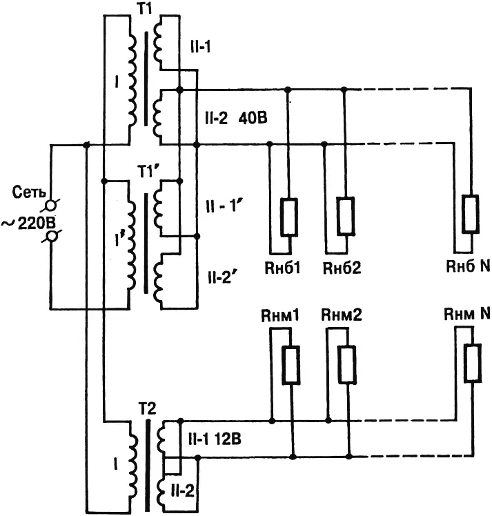
To power thirty large heaters (one per colony), I recommend using two standard 190 W transformers TP190-5, stepping voltage down from 220 V to the required 40 V. That even leaves a power margin (only 204 W needed instead of 380 W), which during continuous operation over a six-month “heating” season proves very handy. The parallel-connected secondary windings, each wound with 1 mm wire and rated for 1.57 A, can deliver almost 6.3 A to the load. That greatly exceeds the current drawn by thirty 6.8 W heaters (5.1 A), providing another assurance of reliability for the large heat-source system.
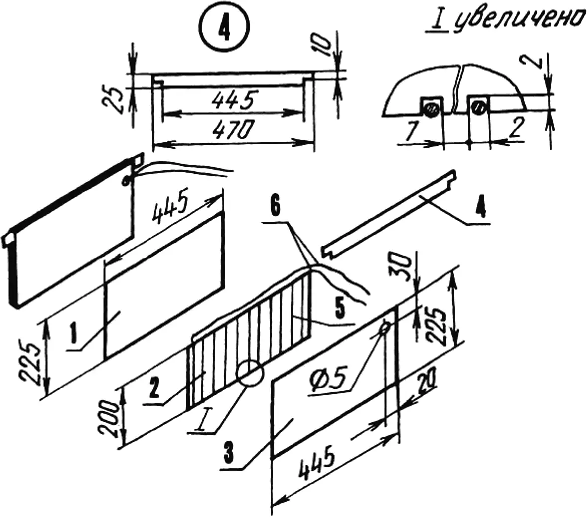
1 — housing panel; 2 — base frame with grooves; 3 — front panel; 4 — corner brackets; 5 — heating winding (Ø 0.4 mm wire, 11.5 Ω per meter); 6 — leads (0.35 mm² stranded copper in vinyl insulation);
parts 1…4 are fiberboard s4; on the small heater parts 1 and 3 are swapped.
What about the small heat sources? With simple calculations from school physics, it is easy to find that powering thirty 1.8 W heaters requires a step-down transformer of 54 W capable of delivering 4.5 A at 12 V. Among those produced domestically, a 100 W unit with two parallel secondary windings (each: 1.8 mm wire, 5.09 A at 12 V), chosen with margin on electrical ratings, fits best. In SKVU such a transformer will run with more than twofold current reserve in the load!
The heater construction is shown in the figure. High-resistance wire is laid in the slots of the base frame, the ends are secured and flexible leads are soldered on. Matching panels are mounted on both sides and everything is nailed together with 20 mm nails, after pulling the leads through a 5 mm hole and attaching the brackets. Off-hive wiring uses insulated wire sized for the consumption current. For 5.1 A this corresponds to 1.9 mm diameter.
The number of turns of the high-resistance heater winding is simpler and more reliably found experimentally. You need an ohmmeter and a frame mock-up. The 600 mm size is approximate and depends on the heater being fitted; its design resistance (235 Ω) is found as voltage divided by current.
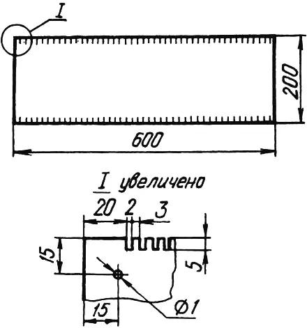
Before winding, lay out the future heater wire on the floor so that its sections do not touch anywhere, and use the ohmmeter to pick the right length from the readings (approximately equal to or slightly above 235 Ω). Place the cut length on the frame mock-up (turns must not touch), secure both ends. Connect the heater blank to the power supply and measure the current. If the value is below the design 0.17 A, reduce the number of turns; if higher, increase it. The tuned winding parameter (51 turns in my case) can be used as the baseline for all further steps.
Make the base frame, cut 3 mm deep slots with a hacksaw, and distribute the winding as evenly as possible. If several radiators are needed, it is best to cut slots with a clamped stack of 6—7 blanks. Lay the tuned high-resistance turns on the frame and assemble the heater.
The calculation procedure for powering the small heat sources and their assembly technology are analogous to what is described above.
Because when building any heater of this design it is not always possible to meet all recommended parameters exactly (different wire diameter and resistance, different load circuit voltages, etc.), it is sensible to apply correction based on the maximum permissible temperature regime.
After the heater winding turn count is determined, make a frame to check heating temperature of the high-resistance wire (the mock-up frame can be used). Keep the distance between slots as small as possible — but so that after laying the winding its sections (at minimum allowable pitch) do not touch. Lay the design number of high-resistance turns in the frame slots and secure the ends. Assemble a simple test setup, connect the heater under test at +20 °C ambient to the power supply, and run the tests.
After 2—3 hours, when the thermal regime can be considered steady, read the thermometer. It must not exceed +40 °C (in my case the temperature was steadily +28 °C), so that with such a heater in the hive eggs laid by the queen do not die from overheating.
1 — heat-resistant insulating base; 2 — frame mock-up with heating winding; 3 — thermometer; 4 — heat-resistant insulation.
When preparing bees for wintering, place the finished heaters at the edges of the nest. From October until the first cleansing flight my SKVU is on, and it switches off only when shaded ambient air is above +5 °C. After the cleansing flight until May 10 the mode changes: the system turns on only when the temperature around is below +25 °C.
Finally, another feature of SKVU use. During wintering the lower and upper hive entrances are fully open!
Energy capability of the system.
A colony of medium strength consumes about 20—25 g of honey per day in the first half of winter. From late February, when brood appears, consumption nearly doubles. With honey energy 3.15 kcal/g and average daily use of 25 g, planned energy expenditure is about 79 kcal.
Total heater power for one colony, as noted, is 8.6 W. Per day they release 173 kcal of heat. But the heaters on my apiary run from mid-October to early May — about 200 days. Over that time, using only 42 kWh of electricity, they deliver (per colony) 34,600 kcal. For bees to release the same heat over the same period they would need to consume almost 11 kg of honey.
Comparing current prices for honey and electricity, the beekeeper’s gain is, as they say, absolute!
Modelist-Konstruktor No. 8’99, A. CHEREVATENKO
Recommend to read
 CORNICE-INVISIBLE
Beautiful curtains on the Windows, decorate the room, provided if they are still hanging nicely. We offer the industry new discreet eaves "String" of wire or cable are not all satisfied,...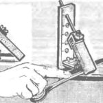 TOUCHSTONE-SNIPER
To execute various works required and various sharpening a cutting tool — so, Turner must change the cutters when switching from one operation to another. However, in everyday life, few...
