Usually, a bicycle is used for five to six months a year, and the rest of the time it sits idle waiting for the new season. But if you equip it with simple devices and supports, you’ll get an excellent exercise machine.
Instead of handlebars, the bicycle-exercise machine has a bottom bracket unit installed (without frame tubes). The bearings from the headset are pre-extracted, and the front fork is tightly tightened with a clamping cone, which prevents it from turning.
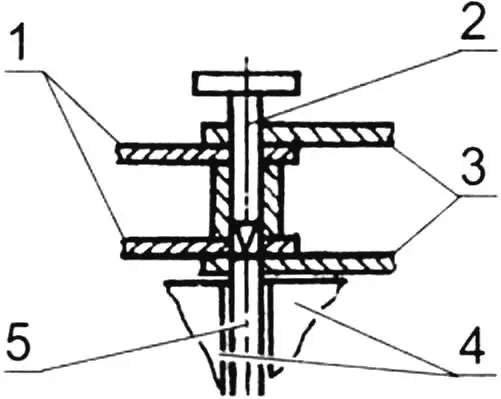
1 – inner plates; 2 – punch; 3 – outer plates; 4 – vise jaws; 5 – axle
The left crank of the standard bottom bracket unit is replaced with a crank with a sprocket connected by a chain to the upper sprocket with the same number of teeth. On the ends of the shafts of the foot and hand bottom bracket units on one side, additional through slots (flats) are cut using an abrasive wheel so that the cranks can be rotated 180° and secured with a wedge. The pedals on the hand cranks are replaced with bushings, and the foot cranks are equipped with toe clips that allow not only pushing but also pulling the pedals upward.
For reliable chain tension, a fixing bushing is fitted onto the handlebar stem. Its length and the length of the hand drive chain depend on the type of bicycle and are determined on-site.
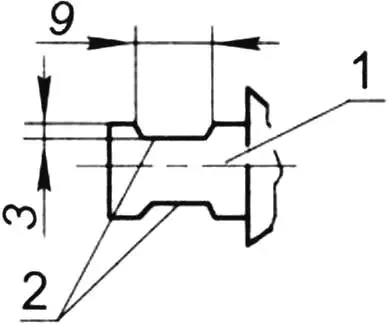
1 – bottom bracket shaft; 2 – flats (slots)
Chain links are disassembled in the following sequence. Placing the chain on vise jaws spread 4-5 mm apart, we drive out the required axle with a 3 mm diameter punch, but not completely, so that it remains in the lower outer plate. Slightly bending the upper plate, we disconnect the chain and remove (or add) links. We connect the links in reverse sequence, striking the protruding axle with a hammer until it fully enters the outer plate on the other side.
To make the exercise machine stand steadily on the floor, a support stand in the shape of an isosceles triangle is used, assembled from half-inch steel pipe. The ends of the pipe are flattened and bent, with holes drilled in them to fit the diameter of the rear wheel axle. A longitudinal stop made from a segment of the same pipe is welded to the stand.
A foot support is attached to the front fork under the crown with an M6 bolt. Rubber tubes are fitted on both ends of the support.
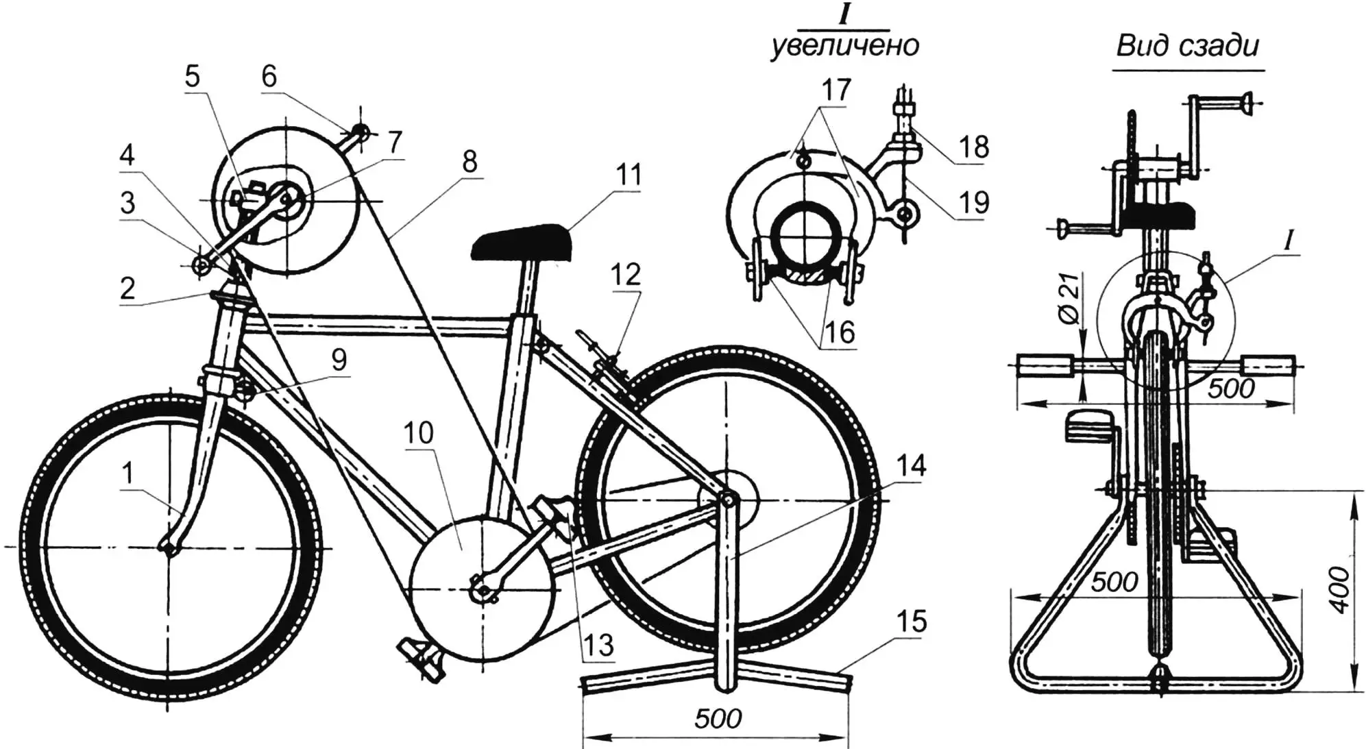
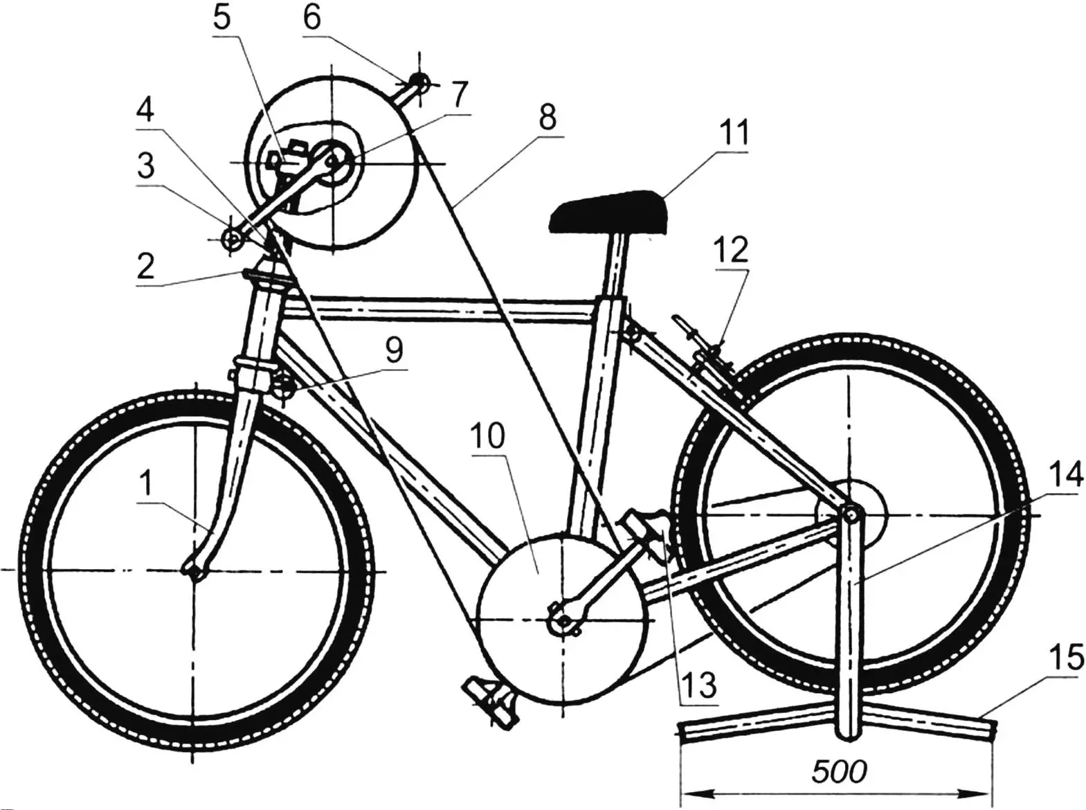
1 – front fork; 2 – clamping cone; 3 – handlebar stem; 4 – fixing tube; 5 – extension clamp; 6 – hand crank; 7 – hand bottom bracket unit; 8 – hand drive chain; 9 – footrests; 10 – additional sprocket; 11 – seat; 12 – brake; 13 – toe clip; 14 – support stand; 15 – stand stop; 16 – brake pads; 17 – brake levers; 18 – adjustment screw; 19 – cable
The brake pads from the rear wheel hub of the bicycle are extracted to allow reverse rotation. The exercise machine is equipped with a rear hand brake, the rubber pads of which are pressed against the rim to create the required load on the pedals – “track resistance.” This is achieved by rotating and fixing the adjustment screw, through which a metal cable passes, installed on one of the brake levers. As the pads wear, the screw is slightly tightened, restoring the load.
Sitting in the saddle and placing the legs from below under the support on the front fork, we slowly move the torso back-down and return to the starting position – thus “working” the abs. By rotating with the hands and (or) feet the corresponding handles and pedals, you can successfully develop the muscles of the arms and (or) legs. If you reposition the left cranks 180°, then by making back-and-forth oscillating movements with the hands and feet, like a rower, you can train the large back muscles. And if you show ingenuity and improve the exercise machine, this will allow you to load other muscle groups as well.
Vladimir GAVRILOV
Recommend to read
 THREE-WHEELED COMPANION
Mushroom pickers, fishermen and tourists have seen many times on the narrow paths of the forests of the Moscow region a strange structure that appeared as silently and as noiselessly...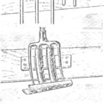 HANGER FOR TOOL
If you list only the major tools used on the farm or garden plot, and we get a decent list: shovels, rakes, forks, hoes, crowbar, cleaver. And even little things — hammers, pliers,...
