No one will argue that a velomobile is good for your health. And for lovers of technical creativity it is doubly useful, as it provides invaluable experience before building more advanced designs.
The velomobile described here was designed and built in the workshop of the Young Technicians’ Station in our city together with club members. It should be noted that the idea of creating it came to me much earlier, so I had prepared the materials and most of the spare parts (in particular, the wheels) myself, at my own expense. However, both the wheels and the materials were mostly taken from abandoned bicycles, so the costs were not that high.
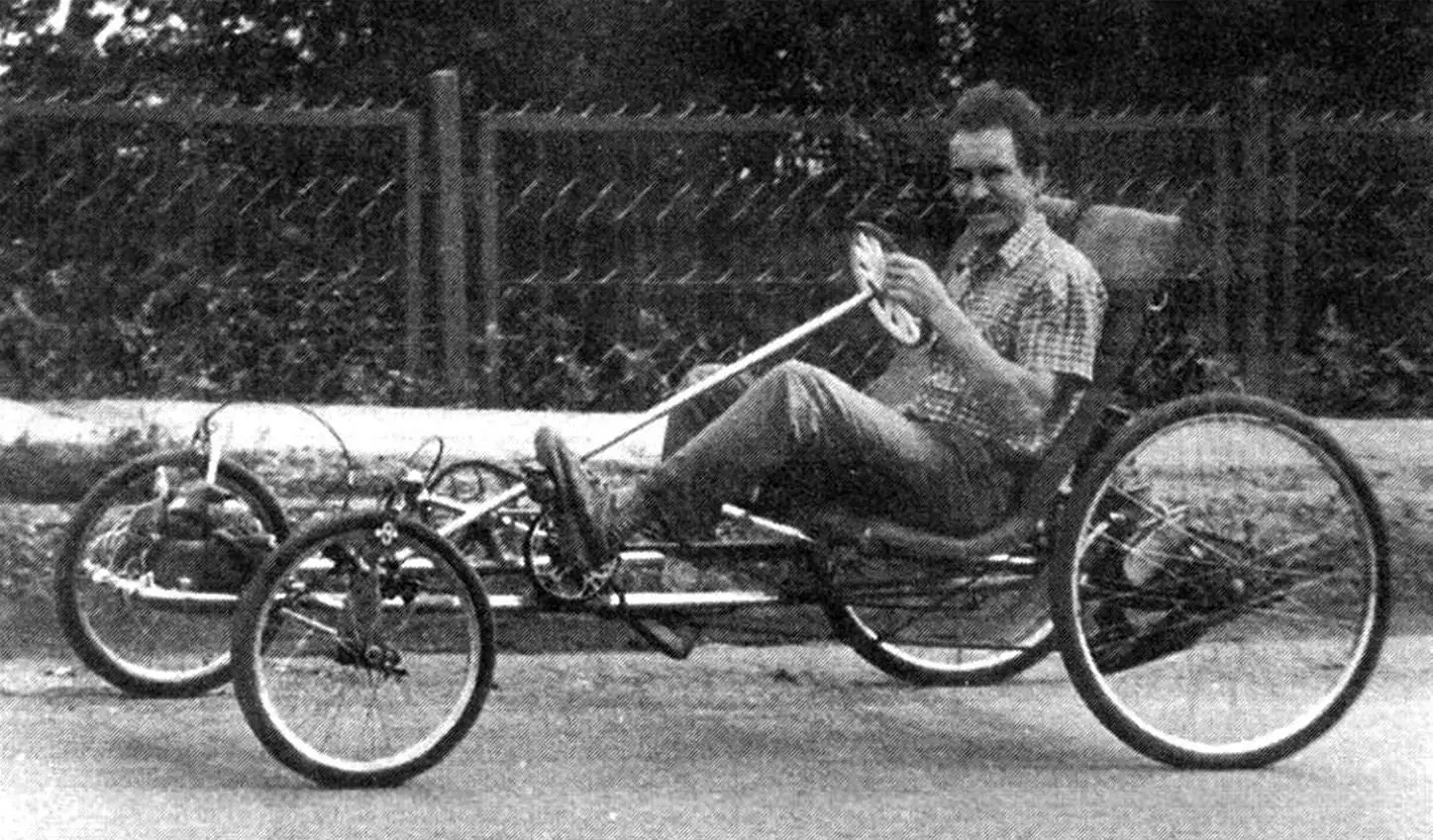
The velomobile is a two-seater, four-wheeled vehicle. The front wheels are steering, the rear wheels are driving. The crew has two pedal drives, one for each wheel.
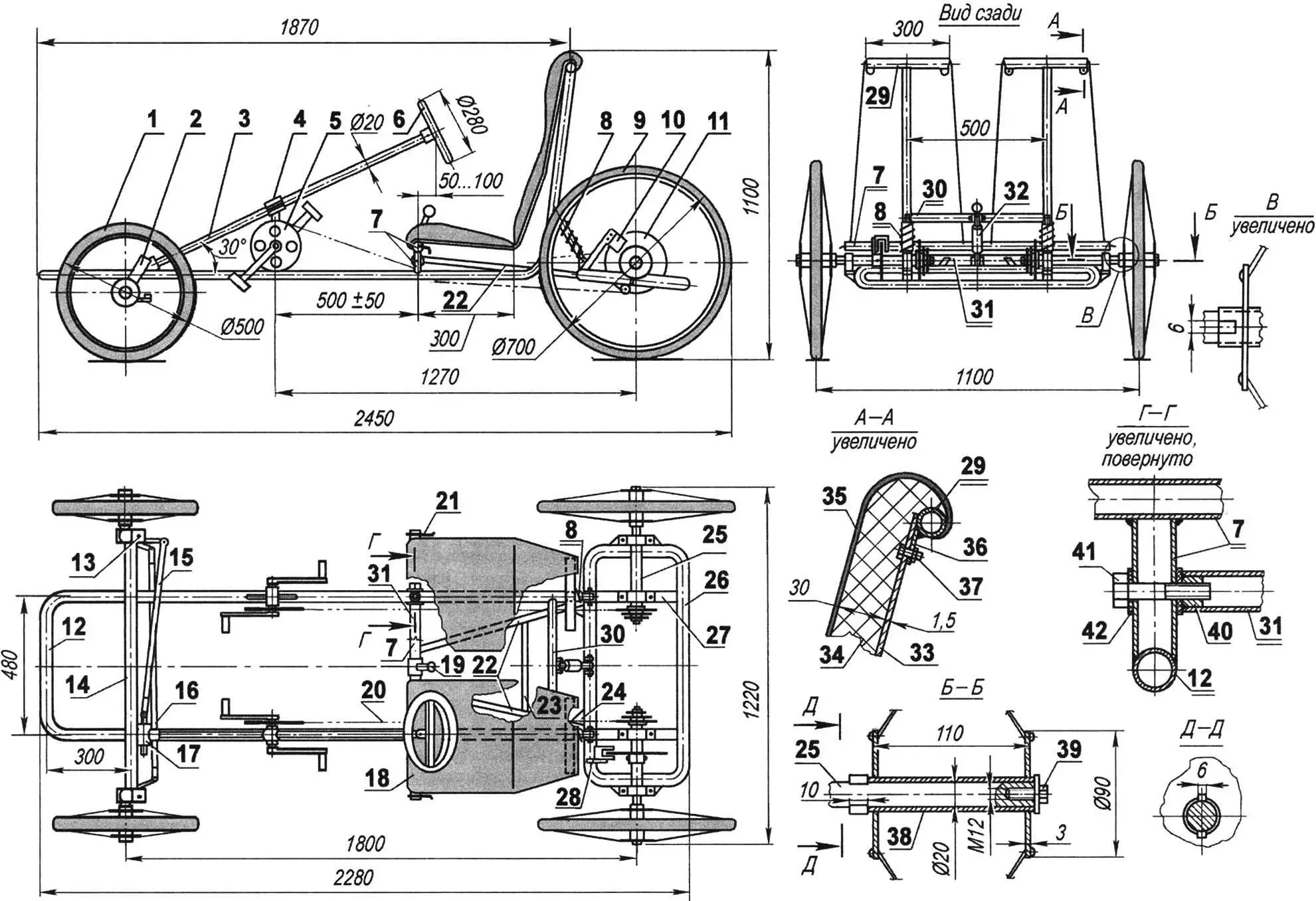
1 — front wheel (from a KAMA bicycle, modified); 2 — steering knuckle; 3 — steering shaft (duralumin tube Ø20); 4 — support post with steering shaft bushing; 5 — pedal unit (from a road bicycle, 2 pcs.); 6 — steering wheel; 7 — portal (steel tube Ø40); 8 — rear suspension springs (from a Karpaty moped, 2 pcs.); 9 — rear wheel (from a Ural bicycle, 2 pcs.); 10 — hand brake caliper; 11 — hand brake disc; 12 — frame; 13 — steering knuckle; 14 — front axle beam; 15 — transverse steering tie rod; 16 — inter-wheel steering tie rod; 17 — steering gear (pinion and rack); 18 — seat; 19 — hand brake lever; 20 — drive chain (from a road bicycle, lengthened, 2 pcs.); 21 — gear shift lever (from a touring bicycle, 2 pcs.); 22 — longitudinal rods of the rear axle subframe (angle 35×35, 2 pcs.); 23 — cross member of the longitudinal rods (steel, round 10); 24 — gusset (2 pcs.); 25 — rear wheel drive (2 pcs.); 26 — rear axle subframe; 27 — bearing shelf of the half-shaft (angle 35×35, 2 pcs.); 28 — hand brake caliper bracket; 29 — seat back traverses (2 pcs.); 30 — rear cross member; 31 — subframe rocking axle; 32 — shock absorber (from a Verhovina moped); 33 — seat base (duralumin, sheet s1.5, 2 pcs.); 34 — seat pad (foam rubber, sheet s30, 2 pcs.); 35 — cover (capron fabric, 2 pcs.); 36 — seat base mounting bracket (steel, sheet s1, 4 pcs.); 37 — seat base fastener (M6 bolt, 4 pcs.); 38 — hub sleeve with rear wheel flanges; 39 — M12x30 screw with washer for fastening the rear wheel; 40 — M10 threaded sleeve (2 pcs.); 41 — axle tip (M10 bolt, 2 pcs.); 42 — washer (capron s3, 4 pcs.)
The frame of the velomobile is welded, with a twin-longeron layout. However, both longerons and the front cross member are made as a single part, bent from a 40 mm outer diameter tube taken from the handrail of a decommissioned city bus. The ends of the longerons are bent upwards and, together with the welded-on traverses, serve as supports for the seat backs.
A rear cross member is welded between the seat back supports; it serves as the upper support for the suspension units (springs and shock absorber) of the rear axle.
The front support for the seats themselves is a low portal resting with its posts on both longerons and also tying them together. In the middle of it a hand brake lever is mounted, and at the ends of the crossbar are the gear shift levers.
The rear axle has a rather unusual design. Its basis is a closed subframe welded from the backrest hoops of metal beds. On its sides, in bearings, are mounted the half-shafts of the driving wheels with a three-speed block of drive sprockets.
A parking brake disc is mounted (welded) on the left half-shaft. The service brakes are caliper type and act on the front wheels. The subframe is connected to the frame (more precisely, to the portal) by means of a rocking axle and two inclined arms made of equal-angle section No. 2.5.
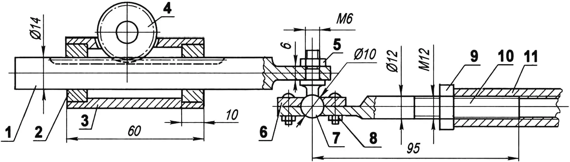
1 — rack; 2 — bushing (bronze); 3 — housing of the mechanism; 4 — pinion; 5 — M6 nut; 6 — cover; 7 — ball stud; 8 — M4 bolt (4 pcs.); 9 — M12 lock nut; 10 — threaded tip; 11 — tie rod (tube Ø16)
The front wheel suspension is independent, on springs. The springs are placed in the bushings of the steering knuckle axles. The suspension travel is small and it damps only small road irregularities. Therefore, to soften blows from larger bumps, additional bump stops made of soft rubber (thick washers) are installed on the axle on both sides of the bushings.
The rear wheel suspension is “semi-independent”. The subframe is suspended on springs (from a Karpaty moped) with a hydraulic shock absorber from a Verhovina moped. The wheels of the vehicle are different: the front ones are from a KAMA bicycle, the rear ones from a Ural bicycle. But both are modified: their hub sleeves were replaced with longer ones (twice as long).
It should be noted that assembling a wheel is not an easy task, and a special jig was made to facilitate this operation. A circle with a diameter equal to the wheel rim was cut from a sheet of plywood, and four support posts were fixed along its circumference at a height equal to the part of the hub protruding beyond the rim. Then a new (lengthened) hub was fixed with a bolt and spacer in the center of the plywood circle, and the wheel was fitted with spokes: first the spoke was inserted into a hole in the hub flange, then its end into a hole in the rim and lightly tightened. After installing all the spokes, the wheel was removed from the jig and the spokes were finally tensioned while checking that there was no “figure of eight” warp.
The front wheels are steerable. The steering system is homemade. It consists of a steering wheel, a tubular shaft and a rack-and-pinion steering gear with a transverse tie rod. The rack and the tie-rod end are connected by a ball joint. The other end of the tie rod is connected to the steering arm of the right wheel knuckle, and from it another, inter-wheel steering tie rod goes to the left wheel. Caliper service (running) brakes are also mounted on the front wheels.
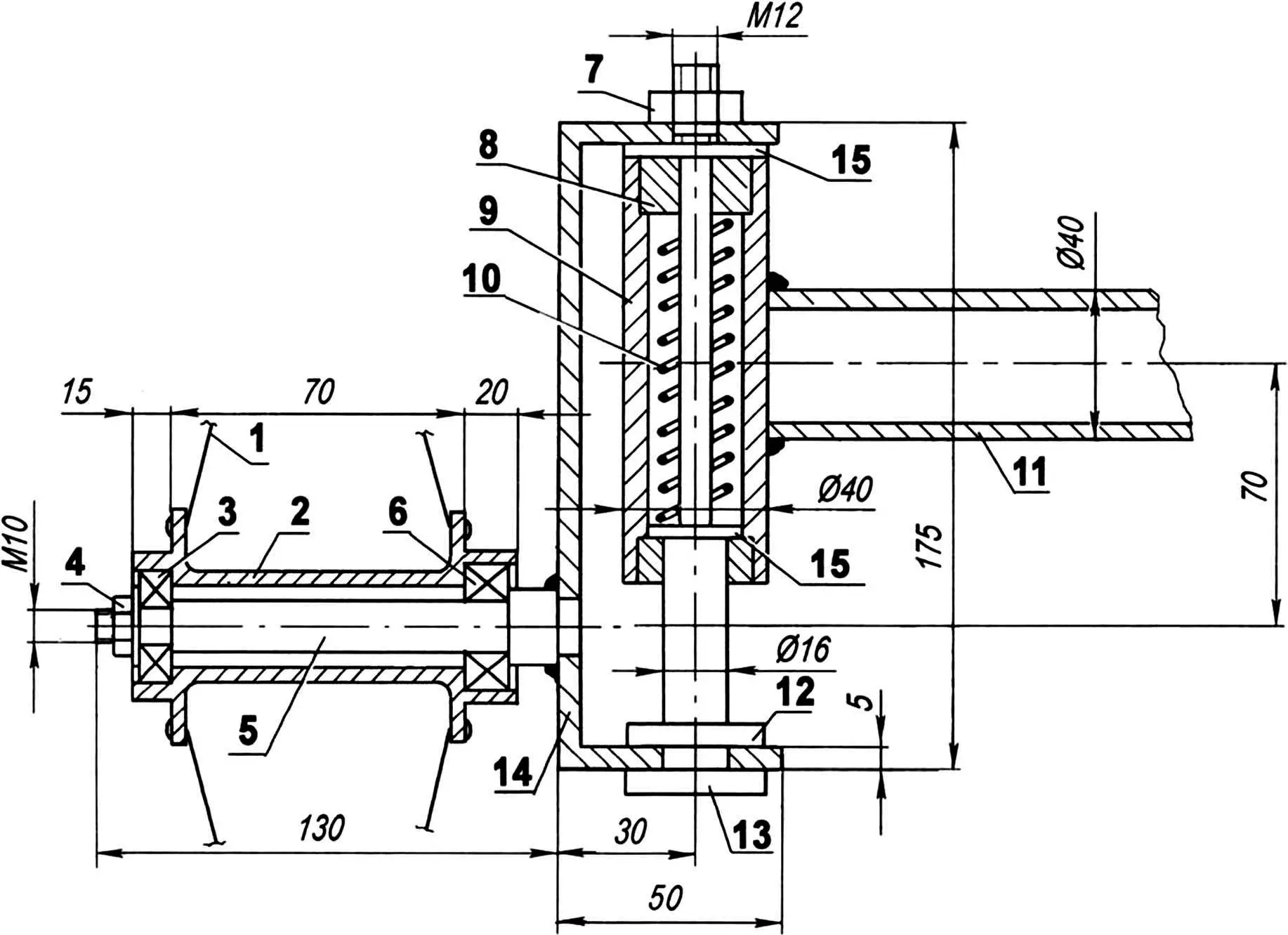
1 — wheel spoke; 2 — hub sleeve; 3 — bearing No. 201 (2 pcs.); 4 — M10 nut with washer; 5 — axle; 6 — bearing No. 202; 7 — M12 nut; 8 — bushing (bronze, 2 pcs.); 9 — bushing of the front axle beam; 10 — spring; 11 — front axle beam; 12 — bump stop (rubber washer s5); 13 — axle; 14 — bracket; 15 — washers
The velomobile is driven by pedals. Both the driver and the passenger have their own independent three-speed drives. Three gears are quite sufficient for travelling over any rough terrain. However, it should be admitted that with an unladen weight of 55 kg it is rather hard for one person to pedal uphill even in the lowest gear.
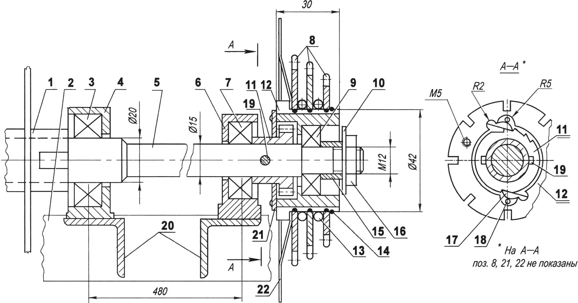
1 — rear wheel hub sleeve; 2 — rear axle subframe; 3 — bearing No. 203; 4 — bearing housing No. 203; 5 — half-shaft; 6 — bearing housing No. 202; 7 — bearing No. 202; 8 — sprocket block; 9 — bearing No. 201; 10 — dust shield washer; 11 — ratchet; 12 — sprocket block housing; 13 — spacer ring; 14 — circlip; 15 — locking sleeve; 16 — M12 nut; 17 — pawl; 18 — return spring; 19 — pin; 20 — bearing shelves; 21 — cover; 22 — bump stop
The pedal units were cut out as assemblies from the frames of old road bicycles and welded to the longerons at a convenient distance from the seats. The three-speed sprocket blocks on the rear half-shafts are homemade; only the sprockets themselves were taken from a touring bicycle. The chain tensioner-shifter is also homemade.
The crew seats are homemade. Their bases, attached at four points to the frame elements, are made of 1.5 mm thick duralumin sheet. A foam mat is laid on the base and covered with a bright capron fabric cover.
On long trips I usually took a polyethylene rain cape with which I covered other necessary items placed in the luggage compartment. The luggage compartment was a net stretched between the longerons and the front axle beam in the nose part of the vehicle (not shown in the drawing but clearly visible in the photograph).
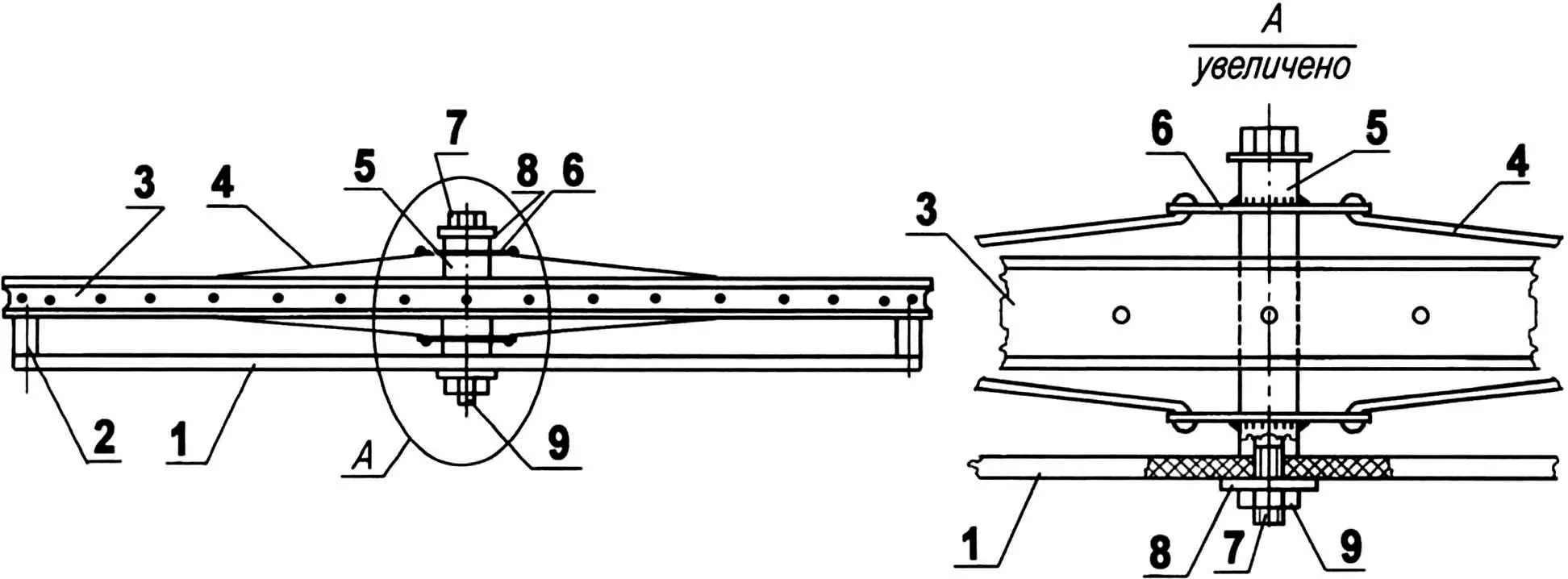
1 — base (plywood s10); 2 — distance bushing (4 pcs.); 3 — wheel rim; 4 — wheel spoke; 5 — hub; 6 — hub flange (2 pcs.); 7 — M10 bolt; 8 — washer (2 pcs.); 9 — M10 nut
I should also note that to connect various elements of the frame and suspensions into a single structure I used a household welding machine, and most of the small rotating parts (axles, bushings, etc.) were turned on a small school lathe.
I admit that in addition to business trips I used the velomobile for two seasons (in the warm time of the year) for commuting to work and back home. On weekends I also took trips into the countryside with my wife or brother.
After two years of operation, an engine D-4 was installed on the velomobile, namely on its rear left wheel, and another “life” of the machine began as a “motomobile”. It is this version of the velomobile, converted into a motor crew, that is shown in the photograph.
“Modelist-Konstruktor” No. 7’2008, A. MATVEYCHUK
Recommend to read
 GHOSTS IN THE ROYAL SERVICE
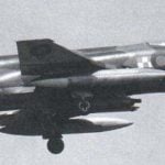
In the beginning 1960-ies to the leadership of the British Navy faced the problem of replacement fighter aircraft "sea vixen" (Sea Vixen) more modern machine. First, the sailors wanted...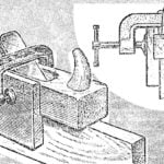 WILL HELP GUIDE
The production of almost any wood product begins with the receipt of smoothly planed boards. And for quality it is important that their plane was not only smooth, but also are mutually...
