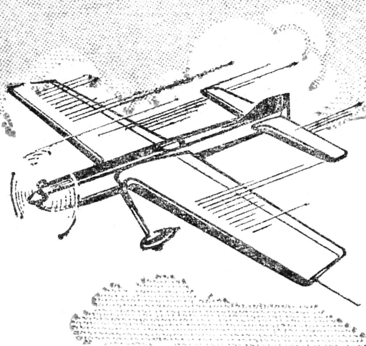
At the 1983 European Championship, many athletes’ attention was drawn to the “aerobatic model” designed and built by Czechoslovak modeler Stanislav Čech. The unusual engine position, increased bending elasticity of the detachable wing, simple and effective contours of the fuselage that read excellently in flight, and a whole range of design innovations benefited the operational, debugging, and flight properties of the new control-line aerobatic model: combined with the pilot’s high skill, they helped win the competition in the F2B class.
We hope that the article, prepared from materials from the “Modelář” magazine (Czechia), will provide significant assistance to Soviet modelers in creating tomorrow’s aeromodeling technology and help more clearly define the directions of design research.
WING is made according to the classic built-up scheme. Unusual is the absence of rigid sheathing of the leading edge of the consoles, which, combined with an extremely lightweight spar, provides significant bending elasticity of the wing. As many experienced aerobatic pilots claim, the deflection of the consoles when performing sharp maneuvers helps to bring the model into straight flight more clearly due to the energetic straightening of the wing on the exit section of the figure’s trajectory.
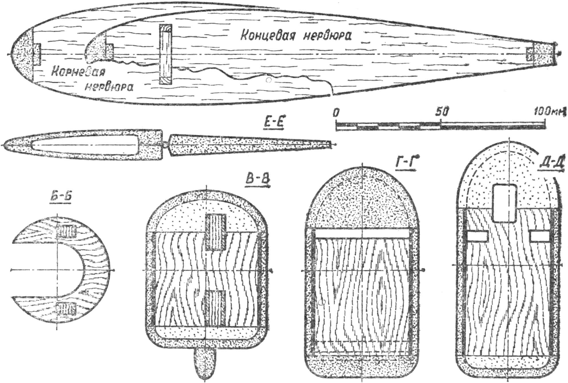
The spar is glued on a flat mounting board from fine-grained, carefully selected pine. The cross-section of the spar flanges is constant throughout the span — 3×5 mm, they are connected into one whole by a balsa spar web of constant cross-section 5X27 mm. Light grades of this wood with vertical fiber orientation are used for it. In the central part of the wing, the spar is reinforced with double-sided sheathing with 0.8 mm thick plywood. The assembly of this most critical structural element is carried out with epoxy resin.
All ribs are made from 2.5 mm thick balsa. The blanks are assembled in stacks and processed “to a taper” for the right and left consoles. Wing assembly — on a flat board-jig. The ribs are put on the finished spar, after which technological edge overlays are glued into their slots, the front one with a cross-section of 3X10 mm, the rear one — 3X5 mm. Then balsa edges with a cross-section of 10×25 mm (front) and 10×14 mm (rear) are mounted. After the glue dries, they are sanded to the wing profile. Wingtips are cut from 7 mm thick balsa plates, near the leading edge small wood scraps are additionally glued on them, allowing a smooth transition from the wingtips to the edge.
Now it’s time to mount the 3 mm thick plywood plates for the control bellcrank attachment. They are glued to the spar between the two central wing ribs. The middle of the wing is sheathed with 2 mm thick balsa veneer, assembly is completed by installing the control line exit unit, which is a duralumin plate with an oblong hole in which tubular bushings with holes for cables are fixed. This design allows selecting the exit points for both control lines separately and within wide limits. In the outer part of the wing, a small container for bulk loading of the console is installed. By trial and error, it was determined that for a model with this engine installation and this weight, 20 g of ballast is required.
The flaps are sanded from light balsa 10 mm thick, hung on the wing only after the complete completion of the external finishing of the model on nylon hinges, just like the elevators. Before sheathing the wing with paper, its central part is covered with a 60 mm wide strip of thin fiberglass cloth with epoxy resin.
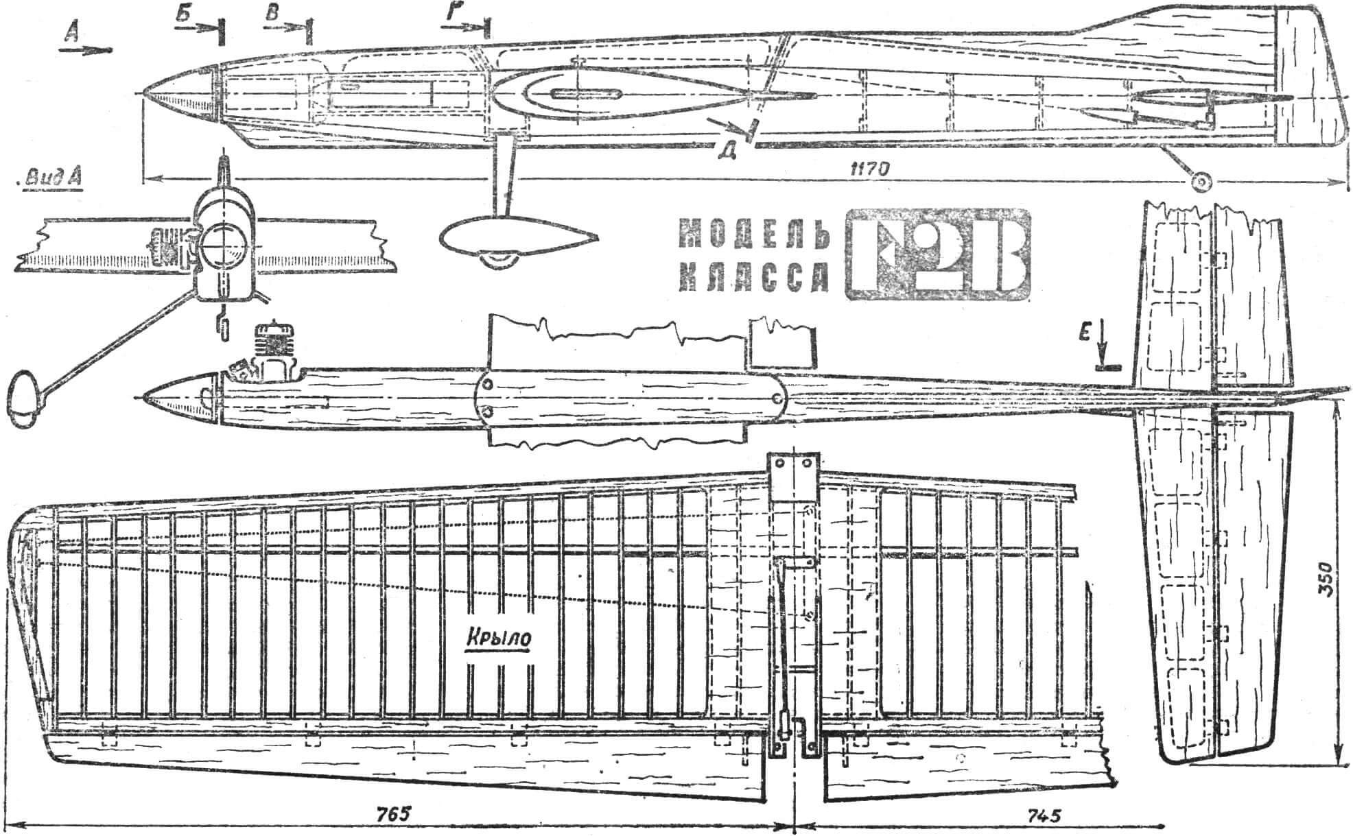
FUSELAGE is assembled on three-millimeter balsa sides, reinforced from the inside from the nose to the trailing edge of the wing with 0.8 mm thick plywood, and four forward frames cut from quality three-millimeter plywood. The engine mount is cut from 6 mm thick plywood, sheathed on both sides with one-and-a-half-millimeter fiberglass laminate and glued into the slots of the first two frames. Between the second and third frames, the fuselage is closed from above with two-millimeter plywood, and from below — with three-millimeter balsa. This forms a compartment for the tank, which is inserted in place through a rectangular cutout in the left half of the side. A hole for the wing is cut in the sides, their upper cut-off part is glued to the center section. Between them, front and rear, three-millimeter rectangular plywood gussets reinforced with fiberglass laminate and carrying duralumin mounting sockets are mounted. The resulting overhangs are joined with overlays of similar construction installed in the second and third frames. Through the metal sockets, two M3 screws pass in front and behind the wing, securely fastening the wing to the fuselage. Under the wing, it is reinforced between the sides with one-millimeter plywood, the upper part of the fuselage is cut from balsa blocks hollowed out to a thickness of 3 mm.
The nose is formed from wood scraps glued to the assembled frame. The removable part of the fuselage, located above the wing, is edged around the perimeter with thin plywood, fastened in front with a pin entering a hole above the frame, in the rear — with an M3 screw. The tail frames of frame construction are assembled from balsa strips with a cross-section of 3X10 mm directly between the bent rear ends of the sides. To complete the fuselage assembly, its lower part is mounted, cut from 10 mm thick balsa and wood scraps. The “dorsal fin” smoothly transitions into the fin, sanded from 10 mm thick balsa. The rudder is hung on strips of sheet duralumin, which allows during test runs to accurately determine the necessary angle of its deflection. After test flights, the rudder is glued permanently.
HORIZONTAL TAIL is all-balsa. The stabilizer is sanded from two plates glued at “points.” After external processing, the blank is separated, the halves are carefully hollowed out and glued together again, now along the entire joint surface. The central part of the stabilizer before its installation in the fuselage is covered with a 50 mm wide thin fiberglass cloth. The elevators are sanded from 10 mm thick plates. Since the assembled stabilizer has a thickness of 14 mm along its trailing edge, a clearly defined step is formed at the transition to the elevators. It ensures low effectiveness of the elevators at small angles of their deflection, which favorably affects the execution of rounded figures of the pattern. At large angles, the effectiveness of the elevators is restored, and the model clearly performs sharp maneuvers.
LANDING GEAR with tail wheel, the struts of the front main wheels are cut from hardened duralumin 2.5 mm thick. The struts entering the fuselage rest on a five-millimeter plywood plate glued between the sides and carrying two sockets with M4 threads. From forward-backward displacement, the struts are fixed by installing overlays on the load-bearing plate, the latter rests on the fuselage frame and on an additional bulkhead. Wheel fairings are hollowed out from balsa, covered with thin fiberglass cloth and mounted on the struts. The diameter of the main wheels is 45 mm, in the tail a small wheel is installed on a two-millimeter wire strut.
CONTROL SYSTEM must ensure completely free deflection of the control surfaces even with full tension of the control lines, but there should be no play in it. Also important is meeting the requirements for the rigidity of individual control elements.
The cables connecting the control lines to the bellcrank and passing inside the wing have a diameter of 1 mm. They are attached to the bellcrank pivotally using eyes bent from one-millimeter OBC wire, the connection points with the cables are wrapped with thin copper wire and carefully soldered. The bellcrank axis with a diameter of 4 mm is placed in two ball bearings and has a length that allows mounting an intermediate lever on it above the wing. At its end is an axis with a diameter of 3 mm, on which the flap pushrod is put. The control horns of the elevators and flaps are bent from motorcycle spokes with M3 threads at the end, which allows, when using threaded end fittings, to select the ratios of deflection angles of the control surfaces, changing them within wide limits. A ratio equal to unity has proven itself well. The flap pushrod is made from three-millimeter wire; the elevator pushrod — a balsa round strip 6 mm in diameter, reinforced with longitudinal carbon fibers and carrying wire ends. Gluing carbon fibers is necessary because the pushrod, unlike the accepted method, is not guided by frame holes, which significantly reduces friction forces in the control system.
EXTERNAL FINISHING begins with covering the front part of the fuselage up to the rear additional bulkhead of the landing gear base with thin fiberglass cloth. After this, the entire model is covered three times with putty composed of talc or baby powder and nitro lacquer. After waiting for this coating to dry completely, the surface is carefully sanded. The wing is covered with thick long-fiber paper, the other elements — with thin paper. The external finishing of the model took about one hundred and ten working hours, which was a good third of all the time spent on manufacturing the aircraft.
PROPELLER-ENGINE GROUP consists of the following elements. The “Super Tiger .46” engine, the most popular among today’s aerobatic pilots. Among its most valuable advantages, one should note its low own mass and high torque at low rpm. Through long selection, the optimal parameters of the propeller corresponding to the characteristics of the engine and model were determined: diameter 300 mm, pitch 170 mm, two-blade propeller. With it, the engine develops 8000 rpm on the ground. A new carburetor venturi is turned, with a passage cross-section diameter of 6.5 mm. A fuel tank with a volume of 90—100 cm3 is enough for six and a half — seven minutes of flight.
Recommend to read
 THE GALLEY ON WHEELS
Travelers of all time, especially on long routes, had a lot of problems with not only cooking in marching conditions, but the transportation of products. These problems are present... CHAIR “ROLY-POLY”
The side of this chair resembles the shape of a seated person comfortably. Obviously, this is not accidental, because it is designed to provide maximum comfort. The fact that unlike...
