 How to ensure reliable and trouble-free fit of a model rocket? The solution to this technical problems struggling for many modelers. According to statistics, more than half of the models after the descent have breakage. But time goes on, experience is gained, more diverse ways of salvation models.
And although we are still hoping for a parachute, continue to work on creating other systems of salvation. This is largely driven by the fact that there are multi-stage models,-models of rockets and space ships: their production modelers spend a lot of SIP and time.
One of the mandatory requirements “Rules of carrying out of competitions on rocket modeling” is the slope of the steps to slow your descent device. Applied ribbon parachutes, pennants. Abroad are even international competitions for the duration of the descent of the model rocket on the ribbon size is 50X500 mm. In competition models on the duration of the descent by parachute of a Soviet modelers have achieved good results more than 20 min.
In the Moscow region decided to complicate the competition for the duration of the descent — for the first time began to hold competitions in several rounds with a limited number of models. This arrangement has necessitated the “plant” model after a certain time and deliver them to the judges for inspection.
The way out of this predicament may be, as a leading modelers, the use of a timer. It should be noted that the first primitive timer (smoldering wick) was used Homel rakatomalala in 1970 at the all-Union competition in Zhitomir.

Fig. 1. Side block:
1 — engine, 2 — bushing engine compartment, 3 — nichrome filament, 4 — cover, 5 — frame simulation, 6 — bushing parachute compartment, 7 — parachute Bay, 8 — isolator, 9 — parachute.
Trouble-free landing the number one problem for rocketmodeler building-models. They demonstrate popey, very similar to the flight of prototypes: full-scale division of stages, the separation of the side blocks. And for the re-launch is necessary to ensure a secure fit of the model.
Interesting work in this direction is in the circle of rocket modeling branch of CSUT of the Latvian SSR. The proposed development, in our opinion, of interest to readers.
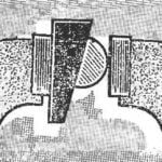
Analysis of the causes of the failure recovery systems prompted us to develop and test some new options. Most interesting is the salvation side blocks rockets is shown in figure 1.
Side block in the area of the frame is cut into two parts: lower — engine compartment, upper — parachute. They are divided cover, which is inserted in the sleeve after how Packed the parachute Sleeve is glued to the top side of the block. Fit (connect) the top and bottom of the sleeve and glued to the bottom. The place of joining of the two parts of the closed simulation frame, made in the form of a strip of paper, half of which is glued to the parachute compartment, and the second as it rises above the parting line, closing it.
The system works like this: at the end of the work of engines of lateral blocks, the latter are separated from the Central block of the second stage, and after one second (and this must be retarder) is activated lifting charge. The upper part of the leaves together with the cover from the bushing, but Ni-chrome filament dramatically slow down its movement, pulling the cover and parachute.
Now let us examine the design of the recovery system of the first stage on the example of rockets “Space”. As can be seen from figure 2, the side surface of the cylindrical body carved oval hole where the paste container. Outside the container is closed by a cap which is tightly fitted around its perimeter and because of this is held in a container. Cover glued thread to the body, so that when the ejection of the parachute she wasn’t lost. The mechanism resembles shooting a slingshot, with the only difference that shoots a parachute.

Fig. 2. A model rocket “Space”:
1 — body, 2 — container, 3 — cover, 4 — parachute 5 — farm first level, 6 second level, 7 — coral, 8 — remote tube, 9 — strand, 10 — bracket, 11 — gum slingshot.
The design of this mechanism is as follows: two elastic bands are attached diametrically opposite inside the container of the parachute compartment at a distance of 1 mm from Highlander the inserted cover. To the place of crossing rubber bands on the outer side of tie the parachute lines, and with internal thread (fishing line 0.5 mm), which passes through the holes in the bracket attached to the body of the rocket, and is discharged to the outside.
Bracket you need to install the SJC to gum passed from the side remote from the tube. The end of the filament can bind the bead to after interfacing with the second stage of the rocket it together with the thread as would have got jammed by the between the housing of the second stage and a farm. The length of the thread should be such that the gum was in the stretched condition. Now you need to fold the parachute and place it into the container, close the lid and the model is ready to run. After undocking, the stages, the thread releases the gum, which she kept, and the ejection of the parachute. This way of salvation is convenient for models that are well fitted, the tank cover does not spoil the overall look of the model and does not affect the number of copies per cell. Please note that the fit of the cover into the container wasn’t too bad. The system can easily be checked without a working engine.
And another way of salvation, the first stage-models where there is no place for installation of the container, that is, the case where the diameter of the rocket body larger than the diameter of the engine compartment just a few millimeters. The scheme of connections and the relative size of steps in the example Zura (Fig. 3).

Fig. 3. Model Suhr:
A — start position B — the time of opening the parachute. 1 — body, 2 — engine, 3 — tube, 4 — parachute 5 — thrust washer, 6-7 — guides, 8 — retaining ring.
In this case, the mounting location for the parachute is only available in the annular gap between the rocket body and sleeve of the engine.
The design of the rescue system is. In case the engine is placed, is inserted into the tube, the ends of which are glued to the guides. The thrust washer is affixed to the inner surface of the housing at the base. Best ring made of duralumin D16T. It needs to be pasted only after the body is inserted a tube with bushings. The parachute attached to the tube and within the annular gap between the housing and the tube. Stop to prevent movement of the engine can serve as a restrictive ring. To the sleeve is moved easily in the body, RUB it with paraffin. Launch stage prepared as follows: to pull the tube out until it stops, put a parachute around her, then gently, so as not to break up the parachute, put it in the chassis, install the engine. After installing other steps it is possible to launch the model. As soon as the second stage engine, above the bushing is formed of high blood pressure that will push up stacked around the parachute. The sleeve will abut the thrust ring. The parachute coming out of the zone of the body, will be revealed. At the same time and undocking steps. The movement of the tube occurs instantly, in connection with which the impact bushings o ring can lead to the rebound of the parachute compartment back into the housing. Therefore, the mating surfaces of the sleeve and rings are made tapered so that, first, the parachute caught on the edges of the ring, and secondly, to reduce the vertical component at impact, and third, to lock the end position of the parachute compartment due to the “jamming” of the bushing in the ring. This system works reliably, but it is necessary to carefully lay the parachute. You should not wrap the engine compartment slings. A few trial runs and guaranteed uptime of the proposed system.
I. ROMANOV, engineer


