
 To make a model of the ship, which would be a decoration in the house I wanted for a long time. But all that couldn’t decide what military ship to take over the original ones seemed too complicated to manufacture, others pretty boring.
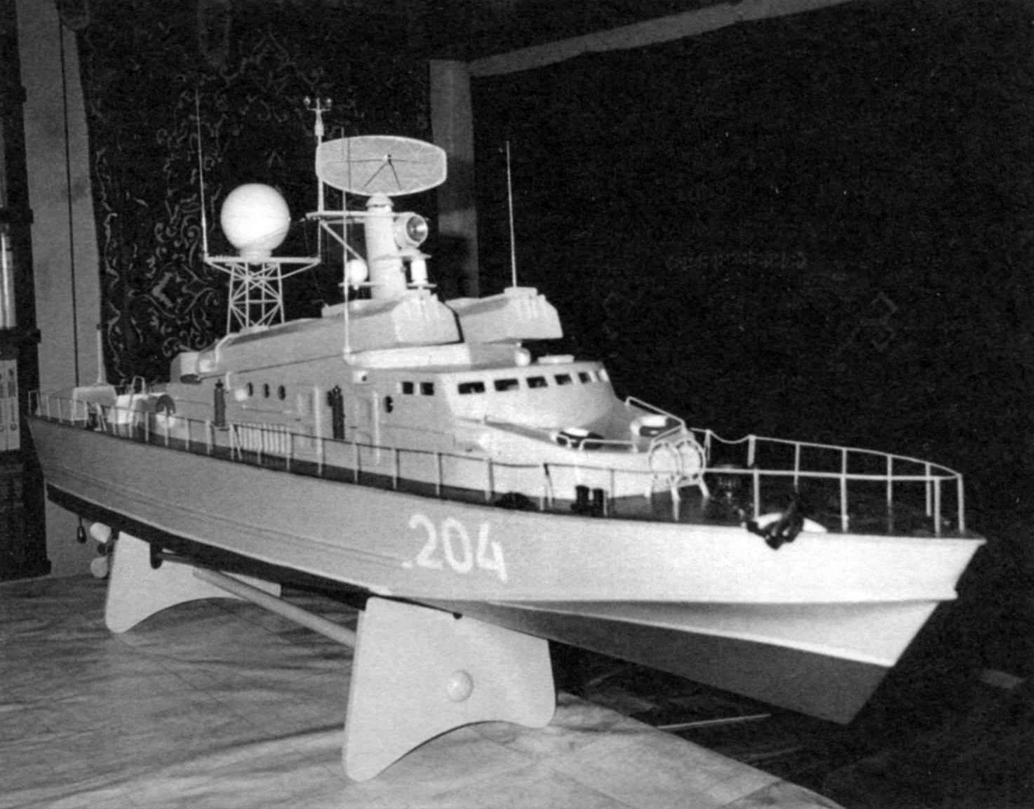
But somehow at leisure, leafing through the binder “Modeller-designer”, in the old (if not ancient) No. 10 of 1969 , I came across a publication with good drawings of models of the missile boat. I was deceived by the rapidity of its appearance, as well as a small number and the relative simplicity of the superstructures on the upper deck. In addition, the model designed over thirty years ago, the then Moscow schoolboy Igor Telezhenko, in my opinion, the shape and the layout still looks quite modern.
This determined my choice. Assumed that my potential audience is not indifferent. And I was right. Now that the model is built, I get to watch her enthusiastically looking at not only children but also adults.
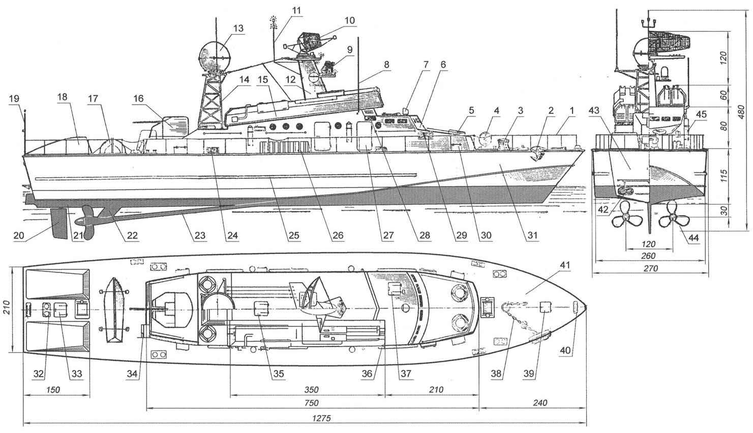
Geometry and exposed layout of the model missile boats:
1 — guard rails (steel wire d0,5);
2 — the anchor (tree);
3 — the anchor capstan (tree);
4 — bow view (wood, tin);
5 — lifeline (tree, 4 PCs.);
6 — cutting (wood and plywood);
7 — sight (tree);
8 — whip antenna radio (4 PCs.);
9 — spotlight;
10 — radar antenna control missile shooting (steel wire d1 and d0,5);
11 — the flagpole;
12 — FLC-mast (wood);
13 — radar antenna control artillery fire (tree);
14 — Grot-mast (steel wire d1,5);
15 — missile hangar (tree, 2);
16 — gun mount (tree);
17 — crew boat (tree);
18 — air intake (tree, 2);
19 — stern flagpole;
20 — rudder (tree);
21 — the bottom of the case (tree);
22 — deadwood (tree);
23 — falsalarma (wood, rod d7, 2);
24 — ventilation grille (wire d0,5);
25 — striker bar (tree);
26 — gangway (tree);
27 — the door (wood, 2 PCs.);
28 — position light;
29 — fire hydrant (4 PCs.);
30 — locker (4 PCs.);
31 — Board (hardboard, s4,2 PCs.);
32 — bollard (wood, 5 PCs.);
33 — after peak hatch (tin);
34 — the ladder (tree);
35 — the average hatch (launch button mechanism of the actuator device);
36 — handrail (wire d1,5,6).
37 — Luke wheelhouse (tin);
38 — anchor chain (steel wire d0,5);
39 — the hatch of the forepeak (tin);
40 — duck (wood, 6 PCs.);
41 — deck (hardboard s4);
42 — exhaust pipe (plug the power supply cord);
43 — transom (tree);
44 — prop (tree, 2);
45 — fire extinguisher (tree, 4 PCs.)
The overall dimensions of your model, compared with those given in the published drawings, increased by half. The length was 1275 mm, width (at midsection) — 270 height (from keel to mast) — 420 mm.
Materials for the manufacture of model used the most ordinary, every homebrew is always at hand — wood and fiberboard (hardboard or masonite), and it went the remains from bruskov or boards and ergalievich panels.
The bottom of the body of the boat, transom and superstructure made of wood, the bottom is laminated from separate blocks spatial and apps — from a single piece of. Power components — frames and keel are made of hardboard with a thickness of 4 mm. Of the same fiberboard made deck and covering boards.
Wooden (pine) blocks bottoms glued between the frames with small allowances from the outside, which are then customized (polished) flush frames. The surface of the hull and superstructures aligned oligomerous with putty, polished with sandpaper of different rooms and covered with paint PF-1305.
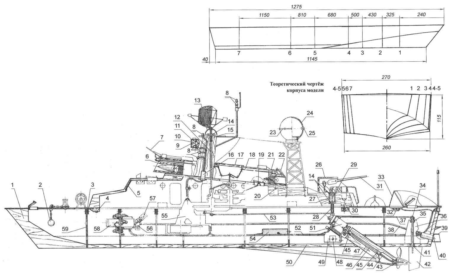
The internal layout of the model missile boats:
1 — block of stem (tree);
2 — anchor the counterweight (lead);
3 — BIMS (DVP, s4, 14 items);
4 — mounting bracket felling (St3, 2);
5 — windscreen (plastic);
6 — cone of the rocket (tree);
7 — cover of Angara rockets (tin s0,5);
8 — way lights;
9 — light ÌÍ2,5×0,15;
10 — glass headlights (plastic);
11 — spotlight (sheet s0,5);
12 — drive shaft revolution of the radar antenna;
13 — fairing (sheet s0,5);
14,35 — bearing series 23;
15 — Cup bearing (D16T);
16 — threaded connection M10x1 mounting the foremast (steel);
17 technology cover (tree);
18 — mechanism for opening the lids of the hangars missiles (2 PCs.);
19 — the lever of inclusion of a reducer (sheet s2);
20 screw pan head mounting Angara missiles (4 PCs.);
21 — hangar;
22 — back cover hangar (2 PCs.);
23 — bezel (wire OVS d1,5);
24 — cover of the antenna of the gun mount (tree);
25 — bracket (steel wire d1, 8 PCs.);
26—tower agostinucci (tree);
27 — the bearing housing (D16T);
28—remote bushing (nylon);
29 — drive shaft rotation of the gun mount (steel wire d2);
30 — M3 screw fixing the cutting;
31 — artillery (tree);
32 — electrodynamic loudspeaker;
33 — mesh air intake (brass);
34 — baller (steel wire d4,2 PCs.);
36 — bracket (tree, 2);
37 — a short rod of the steering gear;
38 — electrical wire;
39 — exhaust pipe (steel sheet s0,5, 2);
40 plug connector 220V;
41 — bearing (nylon);
42 — rudder (tree, 2);
43 — glass bearing (nylon bearing not shown);
44 — flexible shaft (spring, 2 PCs.);
45 — bearing (bronze, 2 pieces);
46 — drive shaft of the propeller (2 PCs);
47 — deadwood prop shaft (tree, 2);
48 — nut M4 square;
49 — the motor bracket (sheet s0,7);
50 — the bottom (tree);
51 — motor;
52 — wiring harness;
53 — long rod drive the gun mount;
54 — electronic control unit;
55 — the drive mechanism (reducer);
56 — mounting bracket of the lamp holder;
57 — neon lamp backlighting logging;
58 — power supply unit with a rectifier;
59 — bulkhead-frame (hardboard, sheet s4, 7 PCs.)
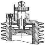
The most complex node of the model — driven gear rotating, spinning, open-developing-closing devices. Suffice it to say that the mechanism applied three types of transmission: belt drive, friction and gear. It managed to achieve greater reduction ratios, combined with quiet operation within acceptable dimensions. To merge all the stage gear in a single gear, had to make a special spatial built-up welded frame. Additionally, to ensure a smooth operation of the mechanism, its kinematic scheme, the first transmission stage (belt drive) included the flywheel. With the same purpose, another wheel mounted on the motor shaft drive the propeller.
A feature of the gearbox is that it has the intermediate shaft of the PTO. When the angular velocity of rotation of the rotor of the electric motor 2500 rpm, this shaft revolves at a speed of 15 rpm. It is excreted through the body the foremast to the radar antenna and rotates the same angular velocity. In addition, on the slave drive this stage of frictional transmission mounted crank whereby through a long rod driven tower and the cannon barrel artillery, and after an additional short connecting rod — rudder.
The last stage of the gear ends with the disk. It rotates with an angular speed of 0.4 rpm.
On the edge of the disc (on opposite sides) installed a pair of Cams for actuation of mechanisms for the periodic opening and closing of lids of the missile hangars (for each of the hangar — its). Each mechanism consists of a mounted on the roller lever, short rod, a pair of rocking chairs on the axes and their connected rods with tips.
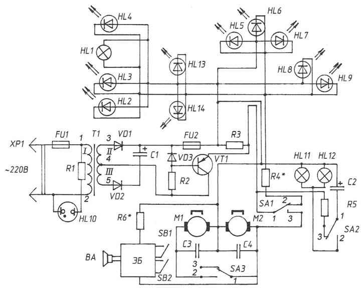
Circuit diagram:
HL-11-12 — incandescent ÌÍ2,5хО,15A;
HL10 — neon lamp IN-3; НL2-9;
13 — 14 — LEDs type АЛ307 or АLЗЗ6, yellow, green and red glow;
VD 1, VD2 — Д226Д;
VDЗ — D 814Б;
C1 — 1000 UF x 15 In;
S2 — 100 — 1000 UF x 15 In;
So ,C4 is 0.1 UF;
R1 — 270К;
R2 — 2K; RZ — 10K;
R5 — 270;
R4, R6 — is chosen.
VT1 — П214 In on the sink.
EB — the electronic block of sound imitation.
M2 — motor ЕG — 530 AD — 9;
M1 — motor DRV-0,1.
ЅА1, AS — switches, like MP5.
FU1 — PN-0,15; FU2 —PN-0,25.
Upon rotation of the drive roller is rolled on the Cam through the connecting rod turns rocking. Rocking in turn push rods, the tips of which slide on brackets attached to the hangar covers and lift them up. When rolling the roller with the Cam on the plane of the disc is closing lids. You can change the location of Cams on the disk or their lengths can change the mode of manipulation covers.
The axis of this disk are fixed two console contacts. Mating terminals are rolled in the threaded holes, evenly spaced around the circumference on the disk. Turn of the consoles relative to each other and rotation response of the contacts can adjust the duration of the sound effect of a missile launch, the Howler, the frequency and the frequency of shots artillery.
The disc performs work of a kind of timer — provides automatic shutdown of the drive mechanism, the edge of the disc is made of small rectangular cut-out, which includes the arm switch of the actuator. Button switch cover is middle of the hatch it is rigidly attached to the end of the lever. For a start-up mechanisms need to click on the end of the lever (the hatch) with your finger and hold it in this position for at least five seconds. The voltage supply to the chassis and tail light is transferred to the electric motor of the drive mechanism. Over a specified time, the drive has time to turn a corner, when the lever will not get in the groove, and will slide along the edge of the disc edge until the last full turn (within 150 seconds). Then the lever under the pressure of the spring jumped again in the groove again and will switch the power to the lights.
Manhole cover when it again lifts off the cabin.
A model boat is installed on the stand with the trim by the stern of 5°.
Technical characteristics of the power supply
Mains voltage: 220+/10%, 50 Hz.
Nominal output voltage: 9
Nominal load current: 0,3
(To be continued)
V. PETROV, S. fish, Krasnoyarsk Krai
Recommend to read
 KMD IN “EARTH” VARIANT
There is an expression: "the Best is the enemy of good." It remains true, however not always. Any Modeler familiar with one of the standard domestic compression motors — KMD-2,5....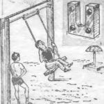 REMOVABLE SWING
If in the yard there is a horizontal bar, it is easy to make a removable baby swing. On the posts, under the crossbar are attached two thick steel plates with U-shaped groove. Lateral...
