 At school, for more than 40 years, engaged in the construction of various mechanisms to facilitate workplace and at home. (In the journal “Inventor and rationalizer” was placed in my article “power saw and pump”, which caused a lot of queries.)
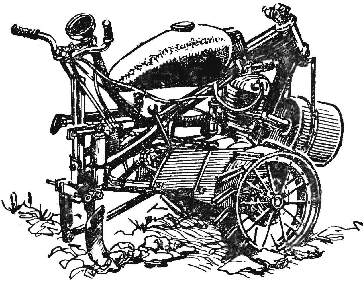
Offer your readers ‘ attention its new development — compact tractors. It is simple to manufacture and can do a good job on the school grounds, greenhouse and floricultural farms. Its advantages are compactness, performance, maneuverability, ease of management.
It is made (Fig. 1) on the basis of the motorcycle “IZH-350”, from which was removed some items, including the headlight, fenders, wheels, seats, running boards, traction lever and the foot shift lever, steering wheel, cables, wiring, signal and vostokfilm.
SUSPENSION
As a guide for wheel axis taken steel pipe (Fig. 2) in which both ends are pressed two bronze bushings, retreating from the ends to 10mm, and it’s set felt seals.
The tube connects to the frame of the bike using the pin pegs. To it are welded the two plates (Fig. 3) having two holes: more before welding the pipe itself is skipped, a smaller threaded stud pegs. On the right end of the pipe along the top welded another steel plate is smaller (see Fig. 2, POS. 3). To it using the two M8 bolts fastened steel l-shaped bracket 6 mm thick (Fig. 5). the other end is clamped by a nut of the top bolt in the engine mount at the front of the frame. In the middle of the pipe drills a hole in which the threaded M10X1.0 screwed oiler. The tube is inserted gladkokrashenye steel shaft with a length of 730 mm, a diameter of 33.5 mm.
The two-wheel minitractor, both leading. The rim of the steel strip with a thickness of 2 mm. At its circumference in a staggered drilled 16 holes Ø 8,1 mm for the spokes. The ends of the rim are welded or riveted. Wheel hubs (Fig. 6) — steel. On the circle have 16 holes under the ends of the spokes. The holes are not through, are arranged in a staggered manner.
Right the hub from the left side has a shank for overmolding a steel disk (Fig. 6), which is then welded. Therein the radius 36.25 mm drilled six holes, which is then deployed under the cones of the fingers of the brake drum (from a motorcycle “IZH-350”), installed on the shaft as a sprocket (Fig. 4, A). To increase traction sprocket brake drum is replaced by a 60 bevel. To replace the bearing the brake drum is inserted into a steel sleeve (outer diameter — 47 mm, inner — 33.8 mm, width — 14 mm). Between the ends of the pipe and hub are steel washers (outer diameter 50 mm, internal — 33.8 mm, thickness — 10 mm).
To transmit rotation from the drive sprocket of the engine to the axle and to increase traction set intermediate shaft with two asterisks. It is machined from steel. One end (Fig. 8) protectives to install the bearing number 204, with the same hand threaded M18. At the other end is the bearing number 205. The bearings are worn steel case with lids having four threaded holes M8 (for attaching to the frame) and three threaded holes M5.
ASSEMBLY OF THE CHASSIS
The axle is inserted into the pipe, the both sides are installed the felt oil seals, washers. Glands become clogged in the pipe close to the bronze bushings. Brake drum with sprocket his six conical projections is inserted into the hole of the disc. At the ends of the three tabs you need to pre-thread M12 (see Fig. 4, A).
After the installation of the hub through the axle are drilled at an angle of 90° two holes Ø 8 mm for the four cone-shaped steel pins. In the process the pins are lined periodically.
The spokes of length 200 mm and Ø 8 mm with one end inserted into the hub bores, and the second hole in the rim. Privaris spokes to the hub, check the rim and welded it to the spokes.
The circumference of the rim bolts or by welding 16 are fastened cross strips of lugs, which is an area 25Х25Х150 mm.
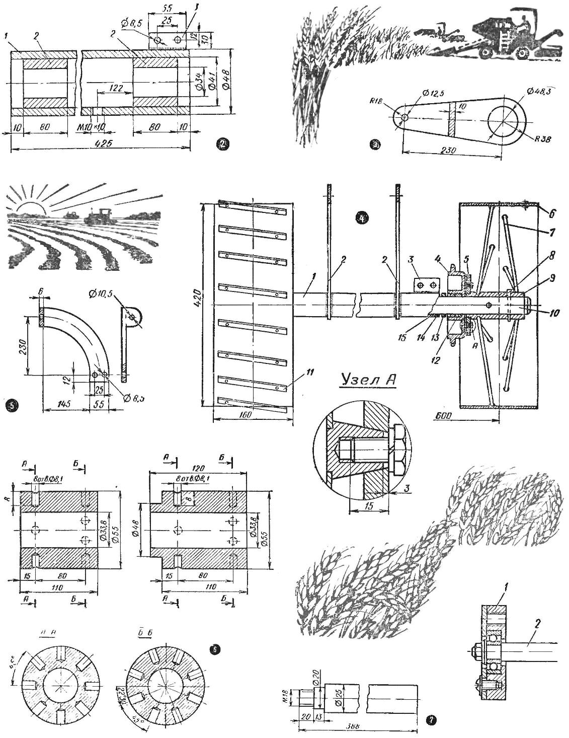
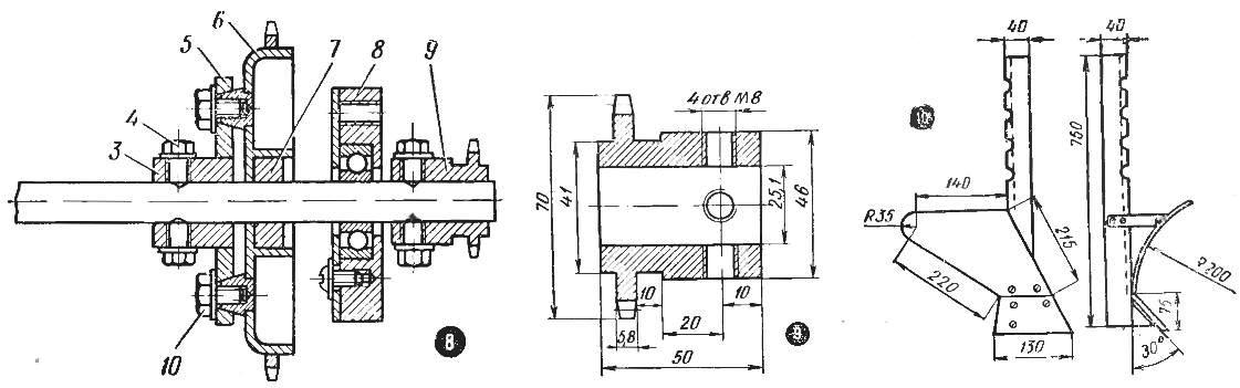
Fig. 2. The guide axle of the tractor Assembly with bushings:
1 — pipe, 2 — sleeve, 3 — plate bracket.
Fig. 3. The plate connecting the axle to the frame.
Fig. 4. The chassis of the tractor, the rear view:
1 — the guide axis, 2 — plates connecting the axle to the frame, 3 — plate bracket, 4 — star (the brake drum from “IZH-350”), 5 — disc right hub, 6 — rim, 7 — needle, 8 — pin, 9 — the hub 10 — axis 11 — area-grouser, 12 — bushing, brake drum, 13 — washer 14 — oil seal 15 sleeve core; And a connection node of the brake drum with the disc hub.
Fig. 5. Bracket for mounting the axle to the frame.
Fig. 6. Wheel: left and right.
Fig. 7. Intermediate shaft.
Fig. 8. Intermediate shaft Assembly:
1 — case bearing No. 204 with lid, 2 — shaft, 3 — sleeve with the disk, 4 — blade, 5 — disc, 6 — asterisk (brake drum with an asterisk), 7 — sleeve, 8 — case bearing No. 205 with lid, 9 — star, 10 — screw.
Fig. 9. Sprocket of intermediate shaft.
Fig. 10. Plough.
Intermediate shaft Assembly (Fig. 8) is suspended to the frame by means of plates with two holes in one end hole Ø 8.5 mm, the other is oblong, allowing the shaft to move, thereby adjusting tension of both chains at the same time.
On the shaft are two sprockets On the right end — 12-bevel (Fig. 9), made of 45 steel with quenching (mount on the shaft with M8 bolts) and brake drum (Fig. 8) with a 42-bevel sprocket, standard. Instead of bearing it is inserted into a steel sleeve (outer Ø 47 mm inner Ø 25,1 mm, width — 14 mm). On the second steel sleeve (outer diameter 48 mm, inner-Ø 25,1 mm, width 50 mm) and pressed with the end face of the welded disk. In the sleeve to shaft drilled four holes for M8 screws.
The transmission from the engine to the intermediate shaft and axle shaft is a chain of 1-15,88. To guard against the dust cover from the right wheel circuit is closed by a metal plate.
PLOW
The form is similar to a standard horse (Fig. 10). Its dimensions depend on the hardness of the soil, depth of plowing and the engine power.
The plow consists of a pillar (area 40Х40Х750 mm), which has a series of holes for adjustment of lifting and lowering the plow. To the bottom of the rack is welded to the inclined plate, to which three M8 screws attaches the blade of steel 45.
The blade is steel, mounted at the bottom of the knife and to the rack. The latter is attached to the frame using plates with holes; the plate is welded To the stud M14 at the ends. This hairpin is inserted instead of the axis.
To maintain a constant depth of plowing there is a special side-ski (of metal), which is due to the rail mount holes can be lowered or raised by adjusting the depth of plowing.
MANAGEMENT
The wheel bracket is connected with the rear part of the frame.
Choke-gas is controlled by lever (lever) and cable air corrector, which flap is raised and secured (turned off) the Decompressor is also a lever, but there is a longer cable. The operation of the clutch is not changed.
Off transmission — linkage-pipe with ball handle.
The gas tank is raised and slightly shifted back, and the gas lines lengthened. Vostokfilm mesh, placed over the wheel and connected with the air inlet of the carburetor of an elastic rubber hose.
When working in hot weather or in heavy soil, the engine may overheat. For cooling it is possible to install centrifugal fan.
A. ULYANOV, Kyshtym, Chelyabinsk region
Recommend to read
 “SHIELD” FROM LIGHTNING – HOW TO MAKE IT?
Dear editors! I am a long-time subscriber of yours, I have used many of the practical publications for home use and I eagerly await the next magazine every time: will there be something... BOARD AND SAIL
On the coast of California, Hawaii, Australia, that is where the huge surf rolls over the waves on a sandy shore, has long cultivated an unusual sport — surfing (from the English. SURF —...
