Dear “Modelist-Konstruktor”! In issue No. 9 for 2004 of your magazine, a material was published about a compressor I made based on a motor-compressor from an old refrigerator. I used it for several years for various needs: paint spraying, tire inflation, and other tasks. But sometimes it lacked pressure and air reserve. Then the idea came to me — to make a larger and more powerful unit using two (paired) motor-compressors. Finding them was easy — working refrigerators that are simply out of fashion are often thrown out onto the street.
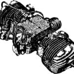
The design and description of the motor-compressor are given in detail (down to the last screw) in issue No. 9’2004 of “Modelist-Konstruktor.” It also includes all modifications for use in an air compressor. Let me remind you of them, as these operations will need to be repeated when constructing a more powerful unit.
- Drill out the remaining discharge pipe using a 10 mm drill bit.
- Cut around the casing rim with a hacksaw (carefully, not to damage internal parts).
- Remove the oil pump and oil intake from the compressor body and fill the space with grease.
- Weld mounting legs to the casing rim so that the grease remains on top.
It would be good to soak the motor winding with Bakelite varnish.
After that, both motor-compressors are mounted on a common frame (facing each other with motor windings) with a 45–50 mm gap between them for air intake. The gap is covered with a fine mesh screen (taken from an old kitchen air purifier).
The rectangular frame is made from 30×30 mm steel angle. After modifying the receiver, it is welded to the tank body.
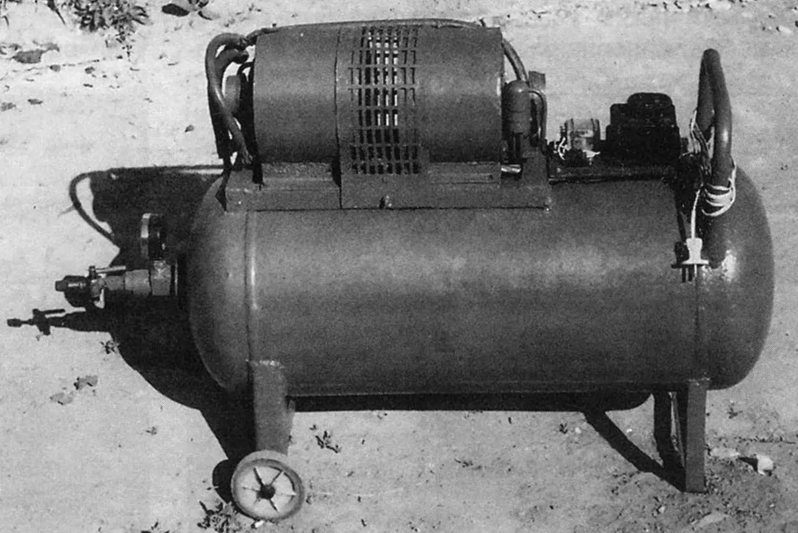
I chose the classical layout for the compressor’s parts and components — like most similar household units made by industry. The base (frame) for all parts was a fairly massive and voluminous receiver — required for the paired motor-compressors. I used a 50-liter liquefied gas cylinder rated for up to 16 atm. Such cylinders are easy to find: many villages are now being gasified, and the cylinders are no longer needed.
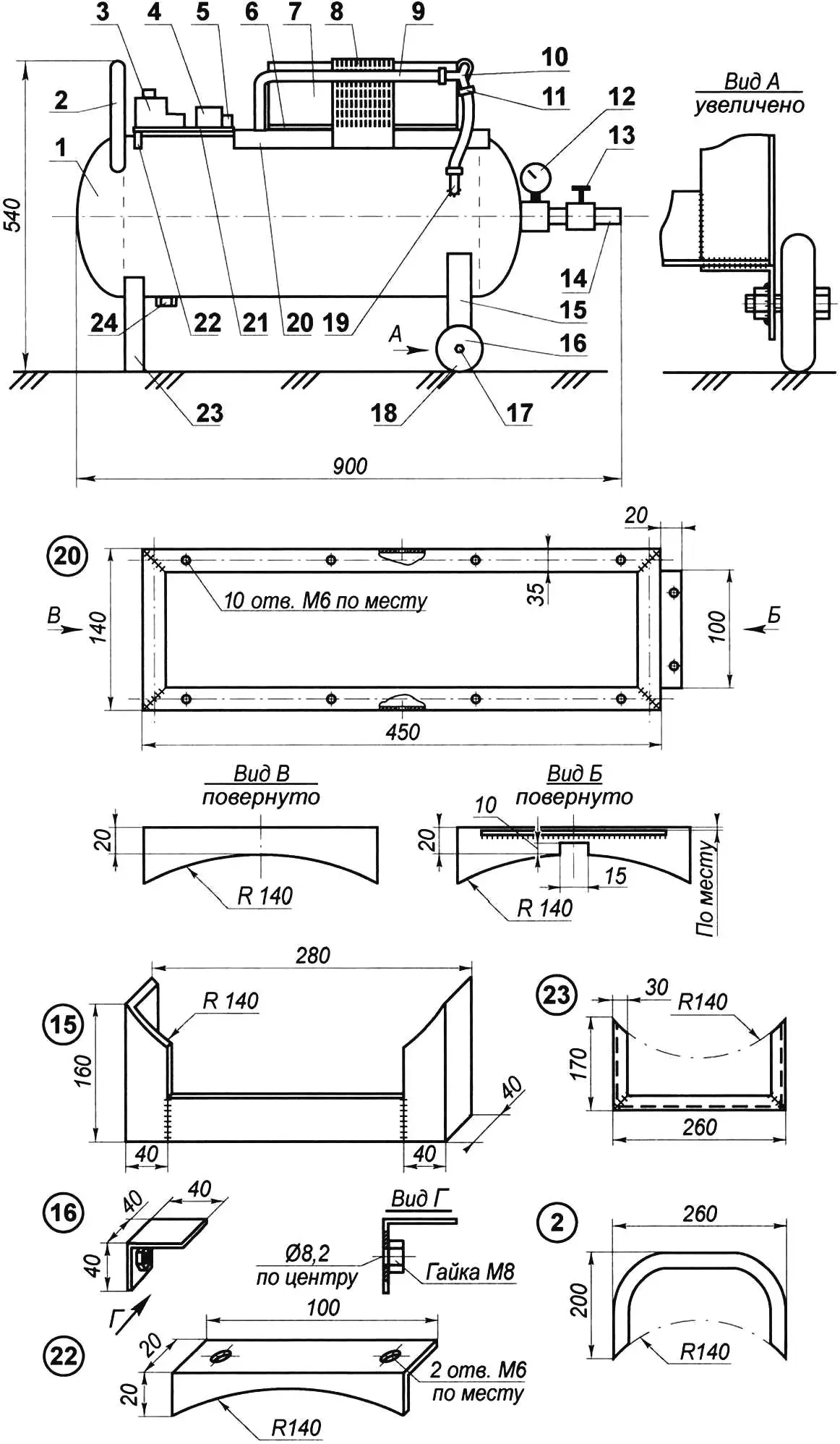
1 — receiver (50L gas cylinder, modified); 2 — handle (pipe Ø20); 3 — starter (from washing machine); 4 — relay (from washing machine); 5 — terminals (from fluorescent lamp); 6 — compressor mounting bracket (angle 20×20, 4 pcs); 7 — motor-compressor (from refrigerator, 2 pcs); 8 — mesh (from kitchen air purifier); 9 — connecting tube (oxygen hose, 3 pcs); 10 — tee (steel pipe Ø7); 11 — clamp (6 pcs); 12 — pressure gauge; 13 — valve; 14 — outlet fitting (pipe Ø10); 15 — main (rear) support (steel angle 40×40); 16 — wheel bracket (steel angle 40×40, 2 pcs); 17 — wheel axle (bolt M8, 2 pcs); 18 — wheel (from baby stroller); 19 — inlet fitting (steel pipe Ø10); 20 — subframe (steel angle 30×30); 21 — electric board (getinax s5); 22 — board support (steel angle 20×20); 23 — additional receiver support (angle 30×30)
I removed the remaining propane from the cylinder. Here’s how I did it: first, I unscrewed the valve. I placed the cylinder upright and placed a container of water above it. Using a thin rubber hose with a metal tube on the end, I filled the cylinder with water, which displaced not only the gas but also the foul-smelling liquid added to propane for leak detection.
I removed the bottom support ring of the cylinder: first, I cut it crosswise, then bent back the petals one by one until they broke off at the weld. I could have left it, but it would have ruined the appearance of the unit.
Before welding, for safety, I again placed the cylinder upright and filled it to the top with water — the vapors generated during welding are cooled as they rise through the water, preventing the formation of an explosive mixture inside.
On top of the receiver (conditionally speaking, since the receiver is cylindrical and lies horizontally), I mounted the compressor unit (on its own subframe made of 30×30 mm angle) and a control panel with starter, relay, and terminal block. Near one end, I welded a handle made from a Ø20 mm water pipe for moving the unit. For the same purpose, I added a chassis under the receiver — on one end (under the handle) is an inverted U-shaped support, and on the other — a similar support with wheels (from a baby stroller).
The first support is made from 30×30 mm steel angle, and the second (main one) is from 40×40 mm angle. The main support has crossbars welded to its bottom, and on them are angle brackets with holes for the wheel axles. Nuts (M8) are welded to the inner faces of the brackets for securing the axles made from M8 bolts.
On the side wall of the cylinder, I drilled an 8 mm hole and welded an inlet fitting (pipe Ø10 mm) aligned with it. One branch of the tee is connected to it via a hose. The other two tee branches are connected to the compressor discharge pipes using the same oxygen hoses. All hose, fitting, and tee connections are tightened with clamps.
To remove water and oil during use, I welded another short threaded fitting to the bottom of the cylinder, drilling a hole in the wall to match the pipe’s internal diameter. This fitting is sealed with a screw-on plug.
The brass valve at the end of the cylinder was also modified. First, a hole was drilled in its body and threaded M14. A pipe fitting was screwed in, and a pressure gauge was attached with a special nut. Another pipe fitting was screwed into the valve outlet — the user’s air hose is connected to it.
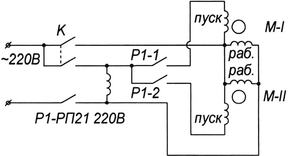
The electrical part consists of a starter (from a washing machine), a relay to disconnect the start windings (also from a washing machine), and a terminal block (from fluorescent light fixtures). All are mounted on a single board made of 5 mm textolite and secured on top of the cylinder. One end of the board rests on the motor-compressor frame shelf, the other on a second support welded to the cylinder.
Power is supplied from a 220V household AC network. The wiring and separate starters allow either one of the two compressors to be turned on independently or both simultaneously, depending on air demand.
One last note. During operation, the original valve of the gas cylinder (now receiver) failed. I had to replace it. I didn’t have the same type, so I used a valve from a Moskvich car’s liquid cooling system. That’s the version shown in the photo.
A. PEVNEV
Recommend to read
 SMALL SPOOL, BUT PRECIOUS!
To find a suitable engine for snowmobiles — the task is far from simple. Series motors in many aspects (in particular, power density) does not satisfy the Amateur designers. This makes... IF THE FUSE BLOWS
When a fuse opens in the apartment is a nuisance, but when this happens in the car — it is almost a tragedy, of course, if there is no spare. Meanwhile, to restore this simple appliance...
