
 A modern casino with excellent gambling attracts many, but to go there dare not everyone. Another thing — home electronic arcade. Here and nice and safe and the costs are minimal. On how to initiate the creation of such games, says the factsheet, which draws on materials from the Bulgarian periodical “Young designer”.
The electronic version of the skittle alley is equally well perceived by both adults and children. Moreover, the sharpness of points, emerging often in the course of the game, each captures so much that off-beat. Indescribable excitement overcomes!
The translation of the “playing field” of bowling alley on microraster — part plastic boxes 100×65 mm — entailed, of course, and a number of conventions. Instead of launching players the balls with well-aimed shots to bring the maximum number of points (or, conversely, directly followed by “milk” knocking-without hitting a single skittles), in the electronic version used pushes the button. With the subsequent trigger circuits and by turning the appropriate number of LEDs in a certain way are oriented on the front panel. Comparing the displayed results, find the winner.
For the implementation of an electrical circuit microthelia, its implementation into the current design does not require any particularly deep knowledge in the field of radio engineering, no hard to find parts. Four logic element IC К155ЛАЗ work in it as a generator of rectangular pulses with a frequency defined by capacitor C1 and resistor R1. From the output of DD1.4, these pulses will arrive (of course, if you press SB1) on an integrated circuit К155ИЕ5 that represents not that other, as the binary counter 16. The numbers appear in coded form. So the decoder (decoder), the duties of which are assigned to the IMS DD3.
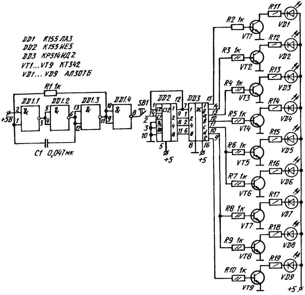
Schematic diagram of the alley, fits in the palm
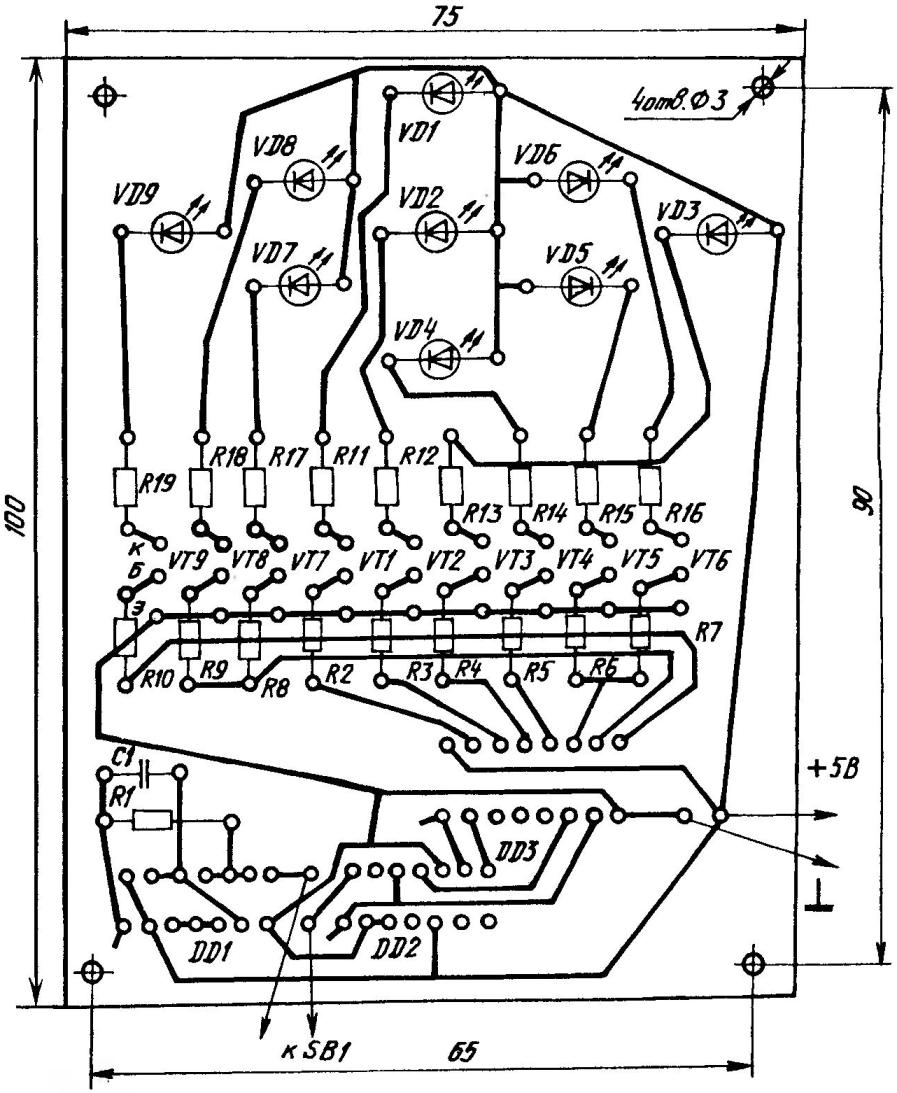
The circuit Board microthelia indicating the characteristics of desoldering electronic components
Integrated circuit КР514ИД2 typically used to control solid state seven-segment digital indicators with separated cathodes (e.g., ALS 324В). In our case, the latter replaced by LEDs. The pins 11 and 10 DD3 they are connected not by one but by two. This gives you the opportunity to get a result as many as 16 combinations of illumination that will match different hits balls on full-sized bowling alley.
With the release of the button SB1, the counter remembers the state, where he remained in contact with the last pulse from the generator. And since the code that is submitted to the decoder, constant, and burning one, a certain set of LEDs.
Power microcephalin, according to the developers, must be supplied from patientage stable DC source. But it is quite acceptable to use ordinary “flat” the battery cell with a voltage of 4.5 V.
The advantages of the device in question can be attributed to the fact that with proper installation and adjustment work is not required.
To embed the printed circuit Board with wiring and electricity, it is recommended to use plastic housing of a suitable size. And on the front panel (cap) it is reasonable to infer LEDs under them with signed numbers dialed points SB1 and not shown on the wiring diagram power switch.
Now for the second scratch for the home game room. It is essentially an electronic version of roulette. Set in plastic box sizes 105x105x30 mm output on the front panel of sixteen LEDs placed in a circle and numbered (numbers from 0 to 15) and the SB1 button and power switch.
With a click of the button starts to work prepared to enable the electrical circuit, simulating the movement of the roulette ball in a circle by switching the LEDs on the principle of “running lights” on the Christmas tree. The next (repeated) pressing of the “ball” is gradually slowing down, until it stops on a particular number, accompanied by an audible signal. That is, roulette remains the roulette even in electronic version.
From the circuit diagram it is easy to verify that the basis for the device the oscillator is made on transistors VT1, VT2 and grouped around them elements, the binary counter DD2, binary-decimal decoder DD1, dynamic speaker and LEDs.
After pressing the button SB1 to the base of transistor VT1 will go positive potential. Once it exceeds the threshold voltage, VT1 opens. To open slightly and VT2, and a coil on the speaker current to flow, causing the sound diffuser.
But paradisica the capacitor C1 begins to discharge, and VT1 will close.
You should re-charge C1. The potential of the base of transistor VT1 will increase again, leading to repetition of already considered process.
The frequency of the generator is mainly determined by the resistors R1, R2 and capacitor C1. If necessary, it can be corrected by changing the resistance R2.
When the button SB1 is pressed again, the operation of the circuit suddenly stops. Switching transistor VT1 goes on for a while. At the same clock frequency decreases. And go, this process will go on until, until the voltage subsides below the threshold of unlocking of the transistor VT1. In a similar way, electronic circuit simulates the rotation of the ball a real roulette.
The pulses received from the clock generator are input to the binary counter DD2 — integrated circuit К155ИЕ5. But I think it can up to 16, while the last pulse does not return everything to its original state. In the elementary case it can be connected to four LEDs which will show only the state of the clock generator. In addition, the encoding… That had developers to introduce the scheme of binary-decimal decoder IC К155ИДЗ.
When you different binary States at the inputs takes DD1 to one of the relevant outputs the signal to control, again one located in a circle of LEDs. Exception — findings numbered 10 and 11, each of which is managed by the not one, but two solid state indicators. So if you look at the counter alternately include LEDs, arises the idea of running in a circle luminous ball of roulette.
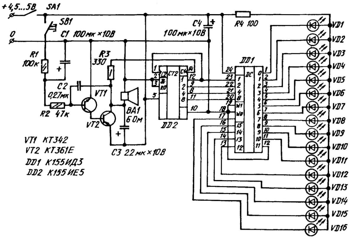
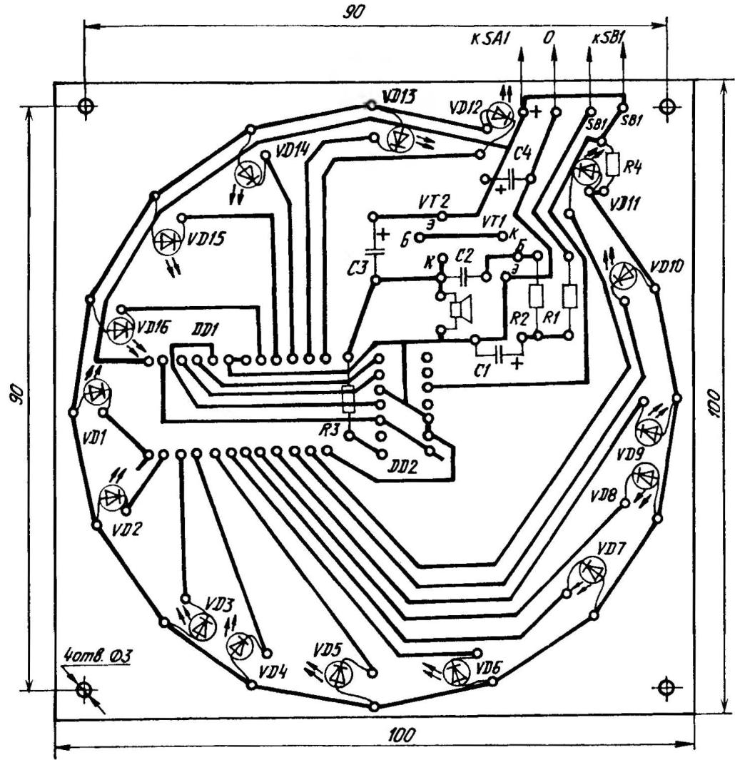
Electrical schematic electronic roulette, and a printed circuit Board with a conventional image montage
When turn on the clock generator, the counter is immediately set to a certain state which is immediately and “will be remembered”. Due to the decoder will Shine with one well-defined led, indicating “unattached” at the moment “happy” number. In addition, work and alarm will sound.
Performing installation of electronic roulette on the PCB, it is important no to make a mess. In this case, the efficiency of the scheme is guaranteed when the supply voltage within the boundaries of 4.5-5 V.
And again. When installing LEDs, remember: a glowing ball of roulette should rotate counterclockwise. Antenna hole (as, indeed, all other operations on the front panel) should be performed with special care, to home-made looked no worse options industrial manufacture.
As for mounting the speaker, here this feature. On the front panel of the housing corresponding to the raster done by drilling 2 mm holes at a distance of 5 mm from each other, and then set the 8-Ohm loudspeaker.
N. KOCHETOV
Recommend to read
 HANDS ON THE PEDALS…
"Ride on this bike is a pleasure, writes us Turner V. Koval from the village of N. Galaxina Poltava region. — Easy climb up steep climbs, with only one hand develop good speed". It is... LIKE CLOCKWORK
At roofing unlikely to lay the slate so that we never need to cut off, adjusting the size of the roof. And someone had to do it, you know what asbestos-cement sheet is not plywood, the...
