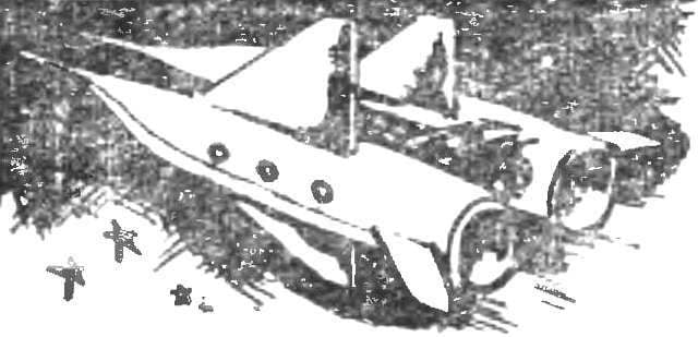
 The idea of the conquest of space is today the minds of people of all ages. Couldn’t stay away from space themes and Junior staff of the laboratories of experiment of Club of young technicians of the Academy of Sciences of the USSR. The subject of their research were plasma and ion thrusters, used to Orient spacecraft in orbit… but only in works of fiction. To make a working model of the plasma engine was conceived by the eighth graders Leonid Klem-Musatov and Yuri Torchinov.
In the rocket motor of this kind operates the reactive force of the plasma jet flowing from the nozzle, and the plasma created by electric discharge. To the power source of the engine of the model is not very complicated and cumbersome, the guys chose the pulse mode. Source of energy served as a capacitor With capacitance 0.5 UF, voltage 10kV, which is charged from the high voltage transformer through the diodes V1—V4 and the resistor R5 (Fig. 1).
The principle of operation is the following. The voltage to which the charging capacitor is determined by the size of the gap between the electrodes of the discharge chamber and contact of the collector (Fig. 2). As soon as the voltage on the capacitor reaches the value breakdown of these intervals, an electric discharge in engine compartment. The air trapped there, under the action of the discharge current is heated to a temperature of about 10,000° K and goes into a state of plasma. The pressure in the chamber rises sharply And the plasma jet through a nozzle with high speed flows out. Reaction force of the plasma jet is passed a model rocket that is connected with the engine. To spin it, the rocket is mounted on the axle through the ball bearing and is balanced by a counterweight. The most complex electric installation unit — power manifold. The annular gaps between the stationary electrodes and the movable pin should be 0,2—0,5 mm. This ensures a minimum of power losses during its transfer from the condenser and will not create additional friction during the rotation of the rocket.

Fig. 1. Schematic diagram of the plasma power source engine.
The size of the missiles and, accordingly, the entire installation can be different, however, the volume of the discharge chamber should be commensurate with the magnitude of the capacitor and the power supply. To the young designers were able to calculate the main nodes of the setup and build your model rockets, the following is a simplified scheme of the calculation of the required capacity.
The basic starting position is that the gas in the discharge chamber of the engine must be heated up to t=8-10°, This allows to estimate the energy of single discharge:
E=VρСV (T – T0). (I)
The efficiency of the installation, determined by the presence of lead wires and gaps in the current collector, can be taken equal to 0.6, Then the energy stored in a capacitor is equal to:
E =CV2/2 = VρСv (T – t0)/0,6 (II)
The formula to calculate the capacitance of the capacitor, if you know what is the voltage U.
To estimate the value of remembering that it is defined by the electric breakdown of the discharge gap model. The process of breakdown in air is dependent on a number of parameters: humidity, surface conditions, and the polarity of the electrodes, forms the external and internal electrodes of the discharge chamber, etc. Approximately can be considered that
U = K·103·dB.
Here d is the total clearance expressed in inches. K1 is 20, if the inner electrode is negative and K2 is equal to 14, if it is positive. These formulas enough to make our simple calculation. We add that if the camera has a cylindrical shape, its volume is equal to:
V = λr2·l,
and the area of the nozzle in the minimum section must be equal to about 0.20 and r2.
Symbols in the formulae:
E — the energy of discharge, j;
V — volume, cm3;
r is the radius of the camera, sm;
l is the length of the camera, sm;
ρ is the air density under normal conditions, ρ=0,129 10-3 g/cm3;
CV — heat capacity of air at constant volume (for our calculations, we can take CV =8 j/g. deg.);
T — t0 is the temperature to which heated gas; t0 is normal temperature of approximately 300°K;
With — condenser capacity, f;
U — charge voltage of the capacitor, V.
We give a sample calculation. Set the voltage U=6000 V, then from the third formula d = 0,45 cm, the Capacitance of the capacitor, we take equal to 0.5-10-6f, then the EU’s second formula will be 9 j, and the energy released in the chamber of the model engine, E=5,4 j. The temperature difference will take equal to 10000° K. From (I) we obtain the value of chamber volume V≈0,50 cm3. Assuming r=d—0,025 : 2 = 0.4 cm, we get 1 = 1 cm and a nozzle diameter of 1.8 mm. elements of the electrical circuit for this specific case is the following: step-up transformer 220X5000 IN capacity of 200 W, the resistor R5 with a wire and 100W.

Fig. 2. The design of the setup for demonstration of the plasma engine:
1 — movable interdigital electrodes, 2 — opposed, 3 — axis, 4 — a model rocket, 5 — discharge chamber, 6 — nozzle, 7 — ball bearing, 8 is a stationary ring electrodes.
The described model belongs to the category of plants with an operating voltage above 1000 V, it is therefore necessary to take special care when working with it and observe the safety rules. Recall the main ones.
First of all, you can’t run the model without the supervision of your group leader or teacher. The run should produce one person, the rest are at a minimum distance of 1 m from the unit. To produce any operations with the model and touch it only after disconnecting the unit from the mains (pull out the power plug from the outlet) and after the expiration of 1 min. During this time, the capacitor C1 is fully discharged through a shunt resistor R1—R4. And one more remark: the value of R5 should be chosen such that the charging current was less than 60 mA. Power supply installation should be placed in closed metal case, that work is grounded copper wire in insulation with a diameter less than 1.5 mm.
V. FOMICHEV, Novosibirsk, Russia


