Components
Will give the approximate cost of all the components that were used in the work. Most components are bought in stores of my town so bring everything in rubles.
Prototype
Debug firmware for Arduino, like everyone, I made on the breadboard using conventional LEDs.
Scheme
With the help of the notorious environment for designing Eagle CAD was modified scheme of the author and the printed circuit Board. Here I added a voltage regulator To 5 volts, changed the sensors with 3 pins expensive Ping on four contact cheap HC-SR04. In order that the illumination of the stairs worked only in the dark, is added to the schema of the Soviet photoresistor FR-764 (you can use another).
The sketch
The sketch uses a freely distributable library for working with led driver M5450 and library to work with an ultrasonic range finder HC-SR04.
#include “lightuino3.h”
//Set the pins to the first sensor
// delay between steps
// Range at which the work sensor
LightuinoSink sinks(clockPin, DataPin, 100, 4);
bClimbStarted boolean = false;
int val;
void loop() {
UltrasonicDownFire();//the Shot, the lower sensor
//Top sensor
if((OurModuleUp.Ranging(INC) < minTopIn) && (OurModuleUp.Ranging(INC) > 0))
//Handling the lower sensor]
if((OurModuleDown.Ranging(INC) < minTopIn) && (OurModuleDown.Ranging(INC) > 0)) {
void climbLightSequence(){
void descentLightSequence(){
void LedsOnUp(){
A little about installation
Since I have the most simple wooden ladder (without podstupenej Board), mount the led strips was carried out from the end of each step.
Is through the length of the cable channel with the laid wires, which are glued with liquid nails. Led strips have the adhesive side, they stay on the tree.
The sensors were installed at the beginning of each of the first stage at the top and bottom of the stairs. As mount used conventional escutcheon for drywall.
From the housing of the power supply alarms have been thrown a dead battery, place it easily fit our controller.
The cover is in place. Place the controller under the landing.
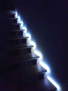
The result
Actually the video does not reflect the real picture. Ladder covers are much prettier and brighter.
VIDEO
Recommend to read IN THE FRIDGE — 0°C! The journal "Modelist-Konstruktor" has more than once published materials about homemade "refrigerators," where natural cold is used for storing food, of which there is more than enough in... THE WING OR SAIL? The question posed in the title, still have not found a final resolution. The first experiments to replace the traditional sail is a vertical wing, by profiling and design friends of the... 
 Good day! In this post I want to share with the Internet community on how I happened to make a automatic light on the stairs in his two story cottage. About four months ago, returning from work in the dark, I successfully slipped and broke two pljusnevyh bone (finger) on his left foot. A whole month had fail in bed, so as to step on the foot was incredibly painful. Then another half of the month was lame without plaster (who had fractures, I’ll understand). After this sad story, I began to think about automating the lighting of the stairs. A bit of tinkering with the search query found a very simple solution in this blog, just based on my favorite Arduino microcontroller. The scheme did not cause any difficulties, but was baffled by the number and length of the wires that I had to mount. Prior to that, did nothing of the sort. To buy ready decisions, or to hire someone is expensive.