“In recent times, hang gliders have become popular — unique successors to gliders. Hang gliders quickly won the love of our youth, and with it, the right to exist.
Naturally, there is a desire to install a small boat or motorcycle engine on a hang glider to fly not only in updrafts…”
This statement belongs to the general aircraft designer O. K. Antonov. From his point of view, the development of conventional and motorized hang gliders, along with other types of aviation creativity, is one of the most interesting hobbies of our youth, amateur designers, and inventors.
This hobby finds understanding and support in the team led by Oleg Konstantinovich. Here, a public design bureau “Hang Glider” has been organized, about whose work “M-K” wrote in No. 10 for 1982.
For several years now, young enthusiasts of the OKB have been engaged in creating ultralight aircraft. (About the first of them — the training hang glider “Slavutych-UT” — the magazine also wrote in No. 10 for 1982 and No. 5 for 1983.) And now the motorized hang glider “Slavutych-M1”.
It was conceived as a means of obtaining experimental data on stability, controllability, and other aerodynamic characteristics of such aircraft. The task was also set — to bring the safety of flights on “Slavutych-M1” to a high level, to obtain material for developing technical requirements and airworthiness standards that a motorized hang glider must meet. After all, in many countries, such ultralight aircraft are used not only for sports purposes but also for chemical treatment of crops from the air, communications, monitoring the condition of forest areas and water areas, and film and photo shooting.
The task was completed in a short time thanks to the fact that the well-proven “Slavutych-UT” was used as the wing.
The first flight on the new “Slavutych” took place on August 1, 1982. During tests conducted under various conditions, it turned out that the motorized hang glider turned out to be successful. It has excellent takeoff and landing characteristics and low flight speed, which in this case is an advantage that contributes to increased safety. In terms of piloting technique, it is accessible to hang glider pilots of average qualification, so M1, like UT, can serve as a “flying desk” for future pilots, designers, and enthusiasts.
A. DASHIVETS, Lead Designer
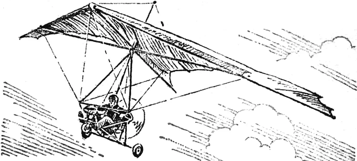
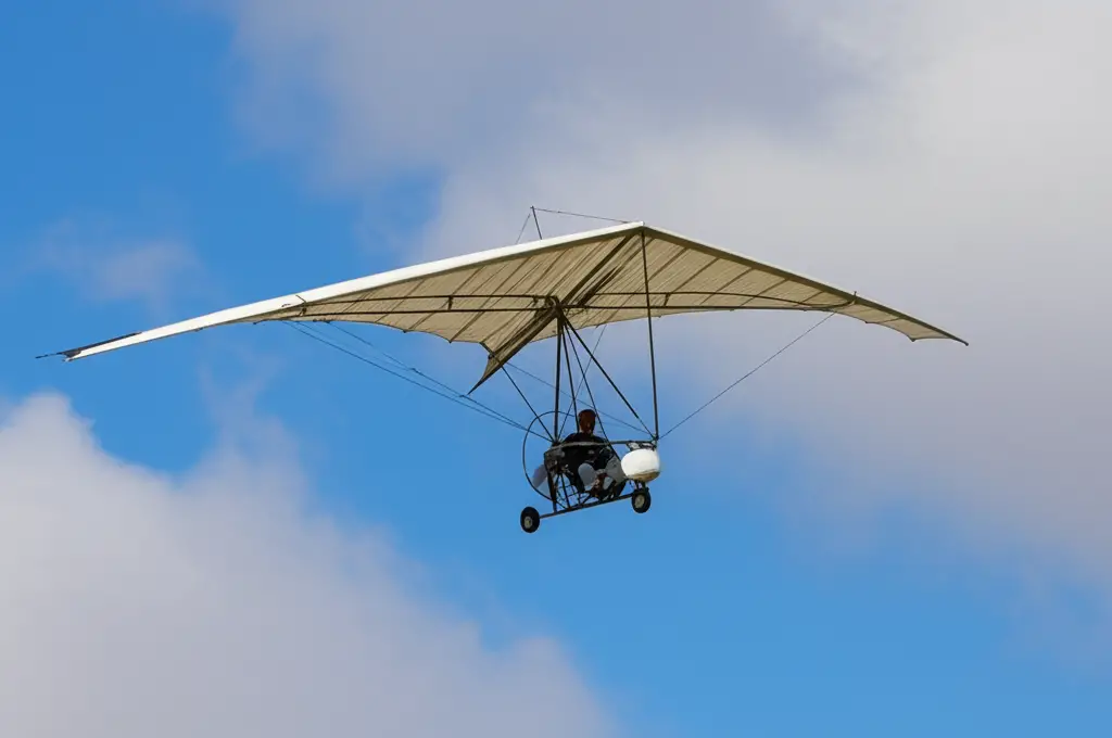
“Slavutych-M1” is a hybrid of a conventional hang glider and a motorized cart. Structural simplicity, low weight, foldability, weight-shift control principle, and the presence of an engine allow significantly expanding the scope of application of this ultralight aircraft.
In the M1 scheme — a flying wing of the wire-braced type with a three-wheeled motorized cart and a pusher propeller. The choice of such a layout is dictated by the following considerations.
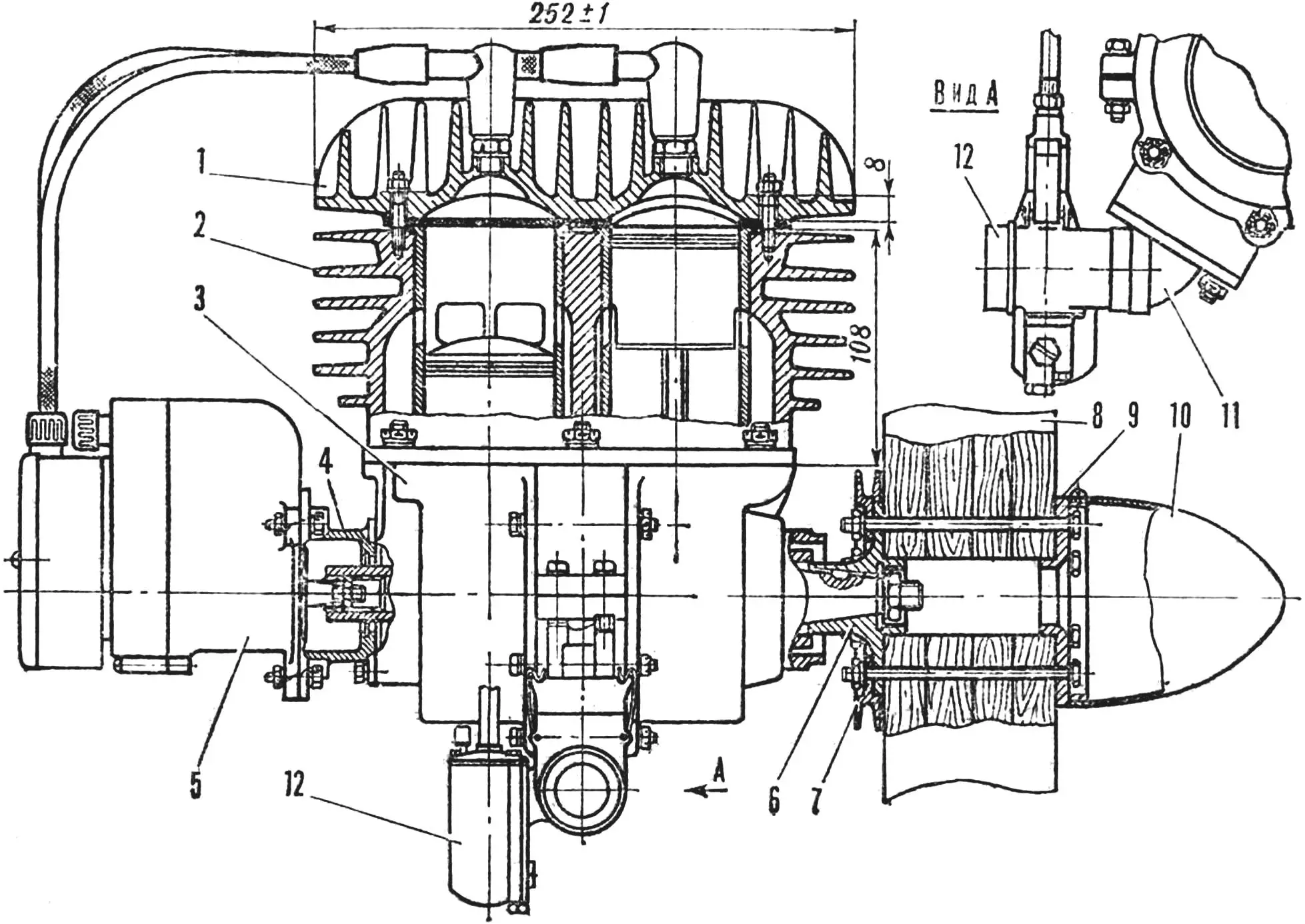
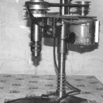
1 — cylinder head, 2 — cylinder block, 3 — crankcase, 4 — transition flange, 5 — magneto, 6 — propeller hub, 7 — starter pulley, 8 — propeller, 9 — spacer, 10 — fairing, 11 — intake pipe, 12 — carburetor.
First, the line of action of the propeller thrust passes near the center of gravity of the aircraft or slightly below it, creating a pitch-up moment. This is desirable: when the engine fails, the motorized hang glider automatically switches to gliding mode, reducing the flight angle of attack. And the three-wheeled landing gear makes takeoff and landing, including forced, safe.
Second, the motorized cart allows increasing the takeoff weight — to increase payload capacity and useful efficiency.
Third, by installing a soft seat, more comfortable conditions for the pilot are provided while maintaining the weight-shift control principle.
And finally, fourth, “Slavutych-M1” is structurally simple and convenient to operate. To this should be added that the motorized cart is also suitable for its ground transportation.
As the wing, the serial training “Slavutych-UT” was used. The main load-bearing elements of its structure are reinforced with D16T tubes: side spars — with internal springs Ø 40X2 and Ø 36×2 at locations with peak bending moments; keel and transverse beams — with reinforcements, respectively Ø 40X2 and Ø 39×1.9. Moreover, the keel beam is reinforced at the location of the lower rear cables, shifted 500 mm forward to ensure clearance between them and the propeller.
The diameter of the side lower cables is increased to 3.5 mm (instead of 2.5 mm on the serial model). The load-bearing channel of the central node is extended for greater balancing capabilities.
A combined control handle for the hang glider and engine is mounted on the trapeze bar, which made it possible to increase the range of center of gravity changes. The motorized cart is suspended under the wing at one point on a two-degree hinge. Otherwise, the wing of the “Slavutych-UT” hang glider has not undergone changes.
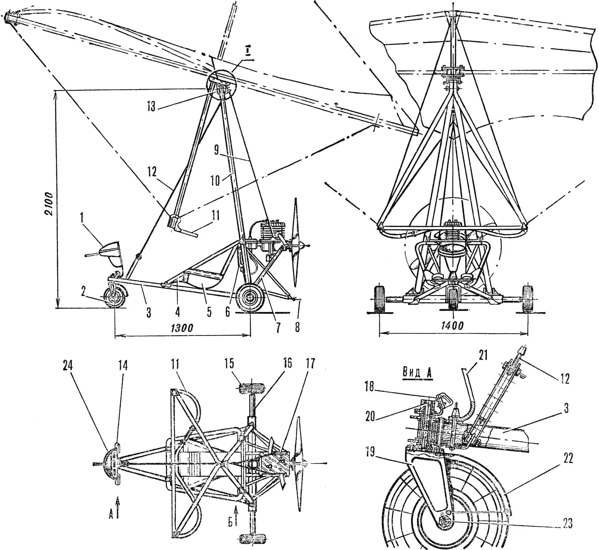
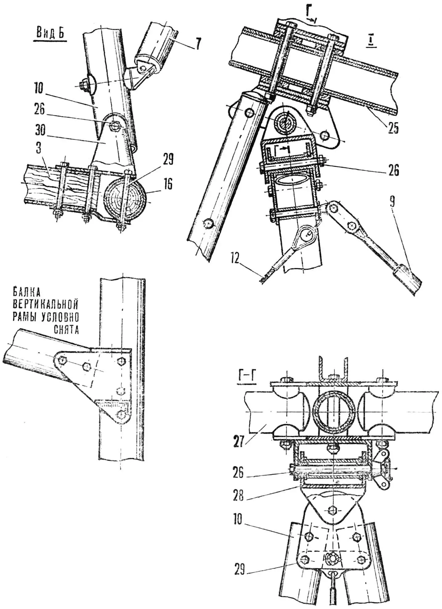
1 — instrument block, 2 — nose wheel, 3 — horizontal frame, 4 — pilot seat frame, 5 — seat, 6 — fuel tank, 7 — engine mount strut, 8 — safety pad, 9 — rear cable braces, 10 — vertical frame, 11 — combined control handle with throttle sector, 12 — nose cable brace, 13 — wing central node, 14 — nose wheel control pedal, 15 — main wheel, 16 — rear axle, 17 — engine mount, 18 — pedal lever, 19 — nose wheel fork, 20 — fork axle, 21 — instrument block bracket, 22 — shield, 23 — wheel axle (M14 bolt), 24 — instrument panel, 25 — keel tube, 26 — connecting bolts M.8, 27 — transverse tube, 28 — universal joint eye, 29 — connecting bolts M6, 30 — power bracket.
The motorized cart of truss-braced construction is made of D16T tubes. Elements of the horizontal triangular frame have Ø 40X1.5; vertical — Ø 40×2. The axle of the main landing gear wheels is also made of tubes Ø 40X2 and Ø 45×1.5. The horizontal and vertical frames are closed by the pilot seat power frame. The seat is sewn from aviation fabric and reinforced with nylon straps and foam; it has safety belts with a quick-release lock. For greater rigidity and reliability, the vertical frame is connected to the horizontal one with adjustable braces Ø 2.5 mm.
All connections of the frame elements are hinged, allowing easy folding of the motorized cart.
On the vertical frame, behind the seat, the engine mount and safety support are mounted. The main landing gear wheels, size 280×85 mm, are from a kart. The hubs are stamped from D16AM sheet 2 mm thick, with bushings with bronze sliding bearings pressed into them. The front landing gear strut — wheel 200×80 mm — is installed in a swivel fork and directly connected to the control pedals.
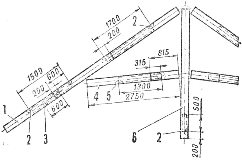
1 — side spar, 2 — tube Ø 40X2, 3 — tube Ø 36X2, 4 — transverse beam, 5 — tube Ø 39X1.9, 6 — keel beam.
Shock absorption during takeoff and landing is achieved through elastic deformation of the motorized cart structure and wheel tires. Brakes are absent.
The power plant is a boat outboard engine “Neptune-23”, converted to air cooling. The cylinder block is cast from AL9 alloy in a sand mold from a wooden model, then mechanically processed, bored, and milled. Cast iron cylinder liners are pressed into it.
The cylinder head is also cast from AL9. The crankcase and crankshaft mechanism with pistons were not modified. The crankshaft is rotated 180° relative to the crankcase. A propeller hub is installed on the power conical nose of the shaft, and on the tail, through a splined coupling and transition flange — a dual-spark magneto “Katek”.
The fuel system is left unchanged. The K-36 carburetor is connected to the engine crankcase with an angular pipe, ensuring a horizontal position of the float chamber.
The propeller is SDV-1 TsAGI Ø906 mm with a pitch of 400 mm. But due to the absence of a reducer (the propeller is attached with six M6 bolts through a hub made of 30KhGSA steel directly to the engine output shaft), it is modified to maintain a sufficient thrust coefficient: the blades are widened twice. By design, the propeller is monoblock, glued from alternating layers of linden and beech wood and reinforced with carbon and fiberglass. The blade tips are sheathed with brass.
Engine control is carried out by a throttle handle from a “Jawa” motorcycle, connected by a cable in a Bowden sheath to the carburetor throttle valve. The engine is fixed on the engine mount with transition profiles resting on four rubber shock absorbers.
The instrument equipment includes an airspeed indicator LUN-1011, altimeter VD-10, variometer VR-10, and cylinder head temperature indicator TST-9. The instrument panel is installed above the front landing gear strut and covered with a lightweight fiberglass fairing. Toggle switches for ignition and signal lamps for critical angle of attack and minimum airspeed are also mounted on it. The sensor for barometric instruments is a forward-extended tube of the air pressure receiver — APD.
The operational limitation ranges of the motorized hang glider are as follows: wind speed no more than 6 m/s, air temperature from —10 to +25°, airfield altitude no higher than 50 m above sea level, maximum takeoff weight should not exceed 180 kg.
The main flight-technical characteristics obtained during preliminary tests generally corresponded to the calculated ones. Subject to compliance with the initial data, they are: maximum speed 65 km/h, rate of climb 2 m/s, cruise speed 55 km/h. takeoff — 40 km/h (with a run of 20 — 30 m), landing — 45 km/h (with a run of 20 m), ceiling 500 m, range 30 km.
MAIN DATA OF THE MOTORIZED HANG GLIDER “SLAVUTYCH-M1”
Masses, kg:
wing — 30
motorized cart with equipment — 22.5
power plant — 22
fuel 8
equipped mass — 82.5
useful load — 87.5
takeoff mass — 170
Dimensions, m:
wing span — 8.8
height — 3.4
Length — 4.4
wing area, m2 — 17.4
wing aspect ratio — 4.4
Power plant: engine power, hp — 23
maximum rpm — 4800
static thrust, kgf — 60
A. KLYMENKO, O. BELOUS
Recommend to read
 Drilling on the table
There was a time when it was difficult to buy any attachment in a shop, and especially a metalworking machine tool. It was expensive, and you had to run around the trading outlets. Today... ELECTRONIC “MIRACLE”
You enter the room, and suddenly light flashes, "alive" is a radio or a tape recorder. To make such a "miracle" the strength of the capacitive relay (the diagram in the figure). ...
