
 For portable electronic equipment need a small volume and weight of the power supply. To solve this problem relatively simply by replacing passive LC and active RC filters.
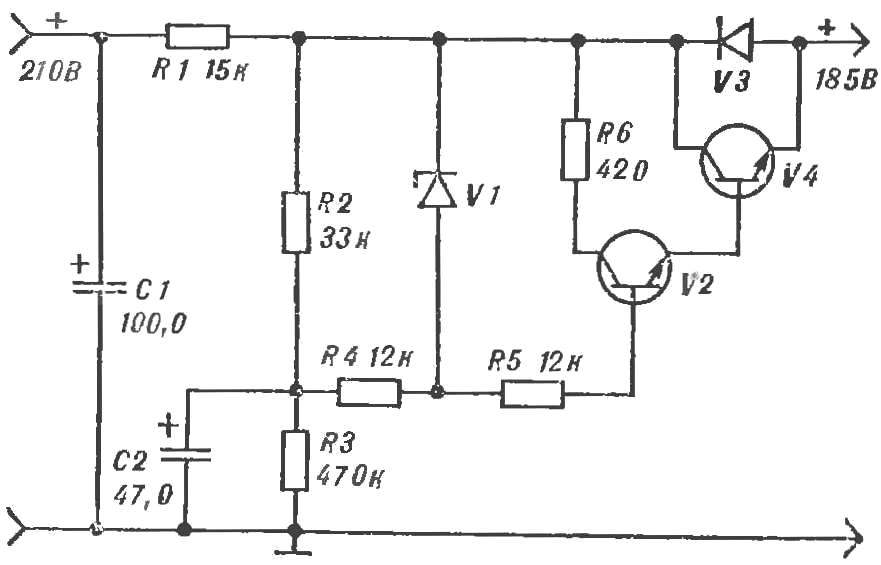
The new filter scheme in figure 1. As soon as the power on, instantly opens the Zener diode V1, the capacitor C2 is charged n opens a composite transistor V2, V4. When C2 is fully charged, the VI closes. Now V2 comes to base well smoothed (R2, C2) DC offset voltage. Therefore, the output pass transistor V4 direct current almost without ripple. (They decreased from 14 to 0.3 V, which is almost 50 times.) And since both of the transistor included in the scheme compound emitter follower, the output impedance of the filter is very small.

Fig. 1. Diagram of the active filter:
V1 — Д813, Д814Д, Д815Е; V2 — КТ312, KT315; V4 — КТ604, КТ605.
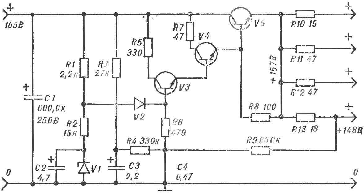
Fig. 2. The complicated diagram of the active filter:
V1 — Д813, Д814Д, Д815Е; V2 — Д202, Д206; V3 — КТ312, KT315; V4 — КТ807; V5 — КТ604, КТ605.
Resistor R1 is a current limiter and diode V3 protects the pass transistor from the voltage spikes of the opposite polarity.
The second scheme (Fig. 2) is more complicated. The base of transistor V3 is powered by a well-smoothed voltage offset. This is why the output of the filter is almost pure DC. The output impedance of the filter is only 30 Ohms.
Recommend to read
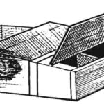 “COTTAGE” FOR NUTRIA
Becoming a pensioner, was engaged in the breeding of the nutria (swamp beavers, or coypu) and saw how it is a profitable business. With the low maintenance costs of these herbivores and...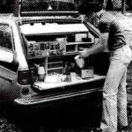 THE GALLEY ON WHEELS
Travelers of all time, especially on long routes, had a lot of problems with not only cooking in marching conditions, but the transportation of products. These problems are present...
