A woodworking machine in a personal household will never be in the way, and when building or setting up a house or dacha, it is simply necessary. However, not everyone has the opportunity to purchase one. Moreover, the machines available for sale don’t suit everyone in everything: either the dimensions are too large, or the capabilities are too limited, or again — the price is too high.
I had to face a similar choice problem. I got out of the situation quite simply — I assessed my capabilities and decided to make the machine myself: the one I needed, especially since I already had an electric motor and standard metal.
To avoid reinventing the wheel, I studied the relevant literature, familiarized myself with several machine development options, but didn’t find one that could be taken as a model. Then, selecting from the collected information what could be useful to me, I proceeded to design my own construction. After making the necessary calculations on paper and drawing sketches of some parts and assemblies, I proceeded to manufacture the machine.
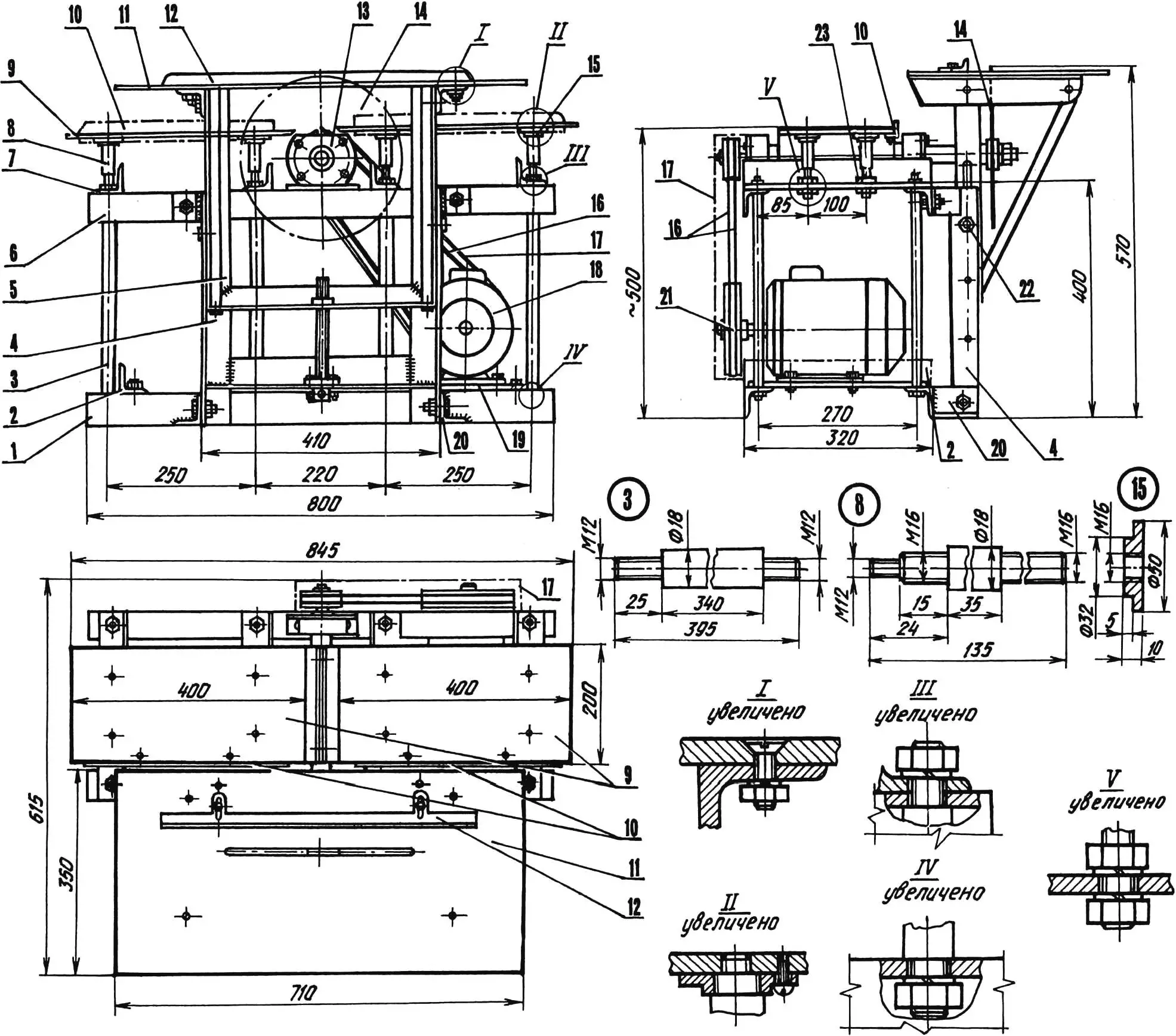
1 — lower longeron (2 pcs.); 2— cross member; 3 — support post (steel rod Ø18, 8 pcs.); 4 — guide post (L395, 2 pcs.); 5 — saw table lifting device; 6 — upper longeron (L800, 2 pcs); 7 — crossbeam (L320, 4 pcs); 8 — planer table post (steel rod Ø18, 8 pcs); 9 — planer table (steel sheet s9, 2 pcs); 10 — limiting bar (steel angle 25×25, L350, 2 pcs); 11 — saw table; 12 — limiting ruler; 13 — driven shaft assembly; 14 — saw blade; 15 — support nut (8 pcs); 16 — drive V-belt (L1120, 2 pcs); 17 — guard (steel sheet s1); 18 — electric motor (3-phase, 2.2 kW power, 1420 rpm); 19 — motor mounting plate (steel sheet s6); 20 — lower bracket (2 pcs); 21 — drive pulley (Ø156); 22 — lifting device fixing bolt M10; 23 — adjusting and fastening nuts M16 with spring washers (16 pcs each).
Parts 10 and 14 on the main view, 2 and 17 — on the left view and 17 — on the top view are shown with dash-dot lines. Position 11 on the main view is conditionally not shown
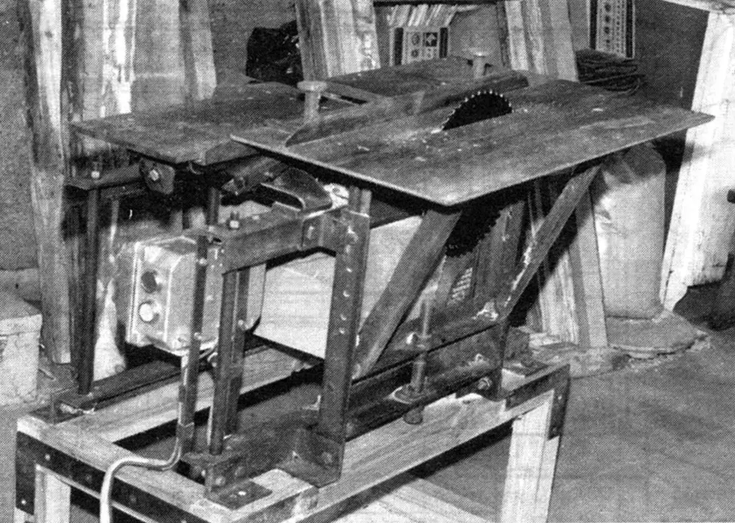
Before starting to describe the construction, getting ahead of myself, I’ll say that the machine turned out to be relatively small in size and simple in design, as well as reliable and productive in operation. It combines a whole range of advantages of branded machines:
- — separate tables for sawing and planing ensure these operations without retooling the machine;
- — ability to install a saw blade up to 350 mm in diameter and adjust the cutting depth without additional devices;
- — changing the chip removal thickness and ensuring high surface finish quality;
- — disassemblable construction for transportation or storage.
The machine frame is a spatial-frame (truss) construction. The support posts (eight of them) are made from 18 mm diameter steel rod, 395 mm long with M12 thread on the ends, and the longitudinal beams (longerons) and cross members (crossbeams) — from 50×50 mm steel angle. The frame parts connections, and other assemblies as well, are mainly threaded, with Grover spring washers. With such connections, the machine can be easily disassembled for transportation or storage. Moreover, welding often causes warping of the construction, so I used it only in case of extreme necessity.
The circular saw table is a solid 9 mm thick steel plate measuring 710×350 mm with a 10 mm wide slot for the saw blade. The slot length is about 350 mm — according to the maximum blade diameter that can be installed in the machine.
Two 50×50 mm angle segments slightly shorter than the table width are bolted to the bottom of the plate at a distance of 205 mm from its center using countersunk head bolts. With their help, the table is mounted cantilevered on a rectangular frame made of 45×45 mm steel angle, which can be moved up and down along two additional guide posts of the frame made of 50×50 mm angle. For this, longitudinal slots measuring 200×10 mm are made in the side flanges of the vertical angles of the frame, and the outer edges of these angles are rounded to the inner radius of the posts (R = 5.5 mm) for tight fit to the guides.
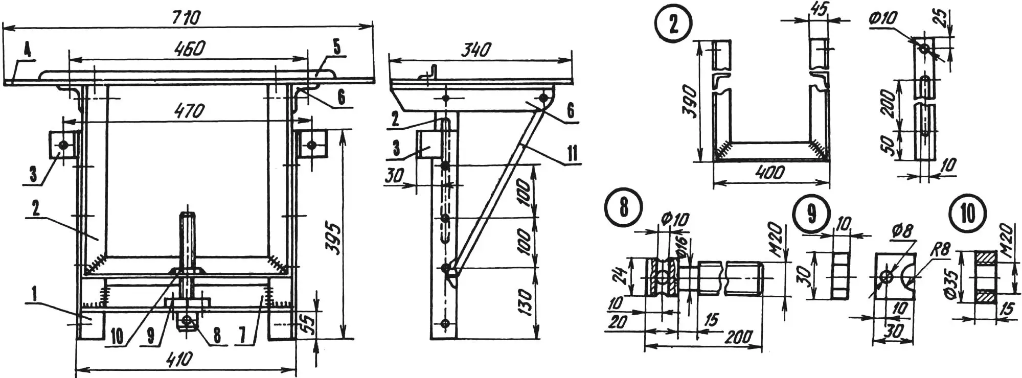
1 — guide post (2 pcs.); 2 — movable frame (steel angle 45×45); 3 — upper bracket (2 pcs.); 4 — saw table (steel sheet s9); 5 — limiting ruler (steel angle 25×25); 6 — console; 7 — cross member; 8 — M20 screw (steel rod Ø20); 9 — assembly washer (steel plate s10, 2 pcs.); 10 — M20 lifter screw nut (steel plate s15); 11 — brace (steel angle 25×25, 2 pcs.)
To mechanize the table lifting-lowering and more accurately set the cutting depth, a screw lifter is mounted below under the frame, secured using an embedded washer on a crossbar made of 50×50 mm angle. The 200 mm long screw is made from 20 mm diameter steel rod, with M20 thread cut on it up to the groove near the screw head. The screw nut is welded to the horizontal flange of the lower angle of the frame. The outer ends of the consoles are additionally reinforced with braces made from 25×25 mm angle. On top of the table, to the side of the saw blade slot, several paired M8 threaded holes are made for repositioning and securing the limiting ruler, made from 25×25 mm angle.
The planer table consists of two symmetrical (relative to the planer rotor axis) halves, made from 9 mm thick steel sheet. They are mounted on the upper cross members (crossbeams) of the frame on different sides of the planer, each on four adjustable vertical supports, for which corresponding M12 threaded holes are made in the table body. The supports, like the support posts, are made from 18 mm diameter steel rod. The upper end of each support is made stepped. M12 thread is cut on the extreme step, M16 on the next, and a round support nut is pre-threaded onto it. After this, the support end is screwed into the table hole, and the nut is fixed with an M4 screw. The threaded hole for the screw is made in place after assembly, first drilling a 3.3 mm diameter hole in the nut and table plate, then the hole in the nut is reamed to 4.2 mm diameter, and M4 thread is cut in the plate. M16 thread is cut on the lower ends of the supports, onto which a limiting nut is threaded before mounting the table on the frame — with its help, the height and horizontal position of the table are adjusted, and consequently — the planing depth. The other nut is a fastening one, it is tightened after adjustment operations. On the right side (in the direction of workpiece movement) on each part of the table, limiters made from 25×25 mm steel angle are installed and secured from below with M4 screws. The holes for the screws are made using the above-described technology for fixing the support nut.
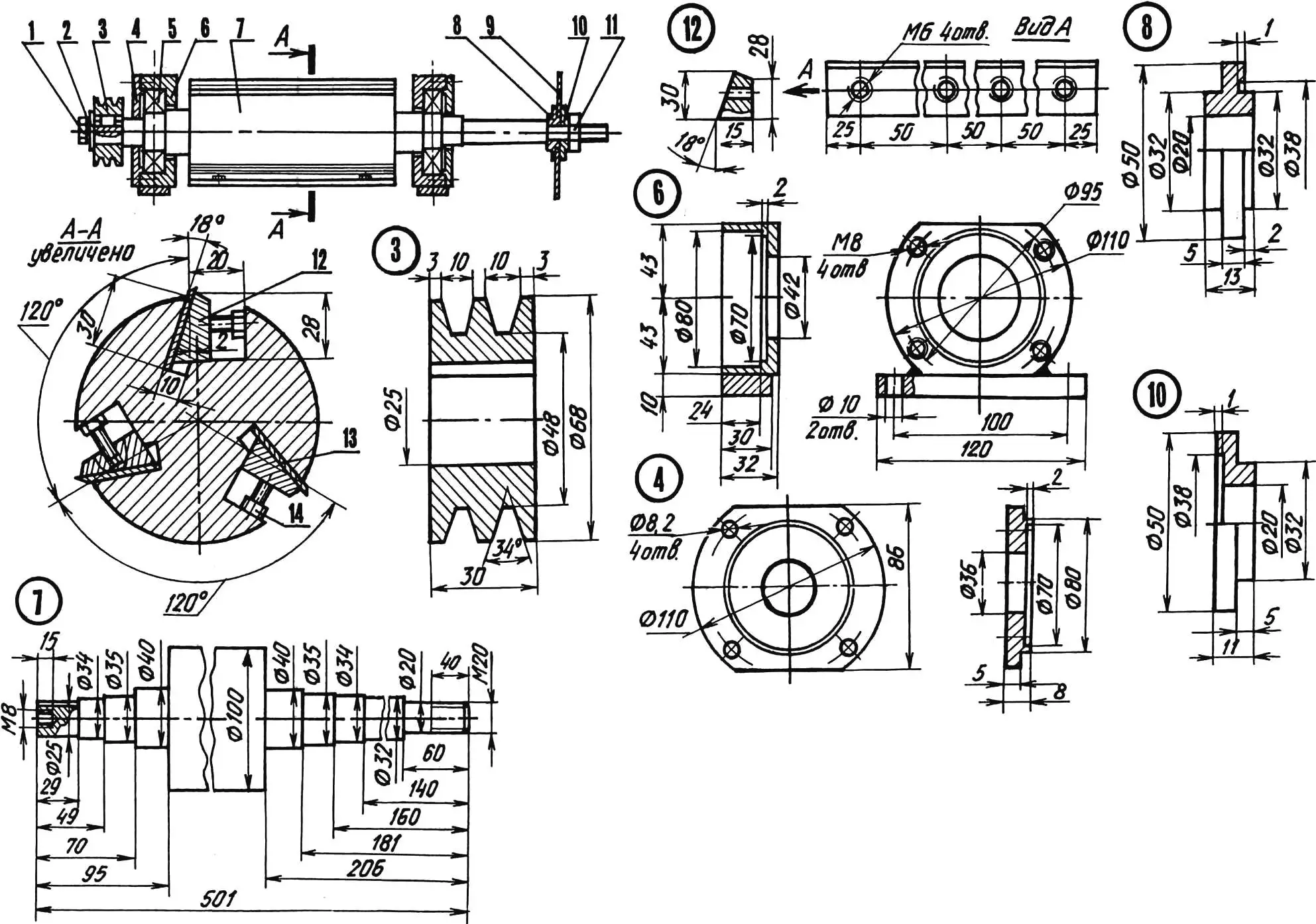
1 — M8 nut with spring washer; 2 — clamping steel washer 25x35x4; 3 — driven two-groove pulley; 4 — bearing housing cover (2 pcs.); 5 — bearing 180307 (2 pcs.); 6 — bearing housing (2 pcs.); 7 — driven shaft (steel 45); 8 — thrust profile washer; 9 — saw blade; 10 — clamping profile washer; 11 — M20 nut; 12 — clamping bar; 13 — planer knife (3 pcs.); 14 — spacer screw M6 (6 pcs.)
The most important assembly of the machine is the driven shaft. It rotates in two 180307 ball bearings with dust seals, installed in dismountable housings. The assembly is mounted on the upper longerons of the frame in its middle part.
The shaft is made as one piece with the planer rotor (its largest diameter). Three longitudinal profile grooves are made in the rotor, in each of which planer knives are secured using clamping bars and M6 spacer screws. Three knives (usually two are installed) increase productivity and surface finish quality.
The shaft is made from steel 45. M20 thread is cut on one of its ends. Here, the saw blade is secured with an M20 nut between thrust and clamping profile washers. A longitudinal keyway is made on the other end of the shaft, and an axial M8 threaded hole in the end face. On this side of the shaft, a driven two-groove pulley is mounted on a key and fixed with an M8 screw with clamping flat and spring washers. Rotation is transmitted to it using two 1120 mm long V-belts from the drive pulley.
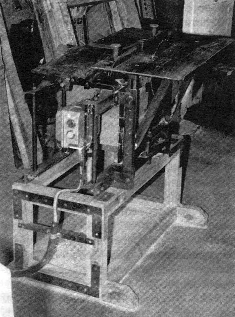
A three-phase electric motor with 2.2 kW power and 1420 rpm rotation speed is used as the drive. It is mounted on a 6 mm thick metal plate, in which longitudinal slots are made for M8 bolts to adjust the drive belt tension by moving the motor. The plate, in turn, is secured to the lower longerons of the machine frame with the same M8 bolts.
To provide the shaft, and therefore the planer and saw, with the necessary rpm, the drive pulley diameter is taken approximately twice as large as the driven one. The machine drive is enclosed with a protective metal guard.
V. AVTUKH, Grodno, Belarus
Recommend to read
 THE SMALL TRACTOR FIELD
The word "cultivator" has entered our lexicon relatively recently. In principle it is the same tractor only built on the basis of single-axle chassis and designed to actuate a... Heavy-duty soil shovel
More than once I had to dig through waterlogged clay soil on the plot. Soil stuck to the shovel in such amounts that working without cleaning it became simply impossible. Removing the soil...
