
 Overcoming water obstacles by troops in the course of warfare is still one of the most difficult tasks of engineering support of Special importance is its start — up phase, the crossing, that is, overcoming water obstacles with the battle, when the opposite Bank defended by the enemy the Crossing ends with the capture of the vanguard or the first echelon of the advancing troops of the bridgehead, eliminating the possibility of enemy direct fire of ferrying troops.
After the capture of a bridgehead on the opposite Bank begins the crossing of all the other elements of the combat formation of troops.
Both terms — “the crossing” and “crossing” for short is often replaced by the term “overcoming water obstacles”, and the term “crossing” is used not only as a process of overcoming water obstacles, but as her view of the assault, ferry or bridge.
According to modern views, the General procedure of overcoming water obstacles by troops, as a rule, is the following.
— the crossing of water barriers by the advanced detachment with the task of capturing the coastal strip and provide boarding and transition to the attack infantry battalions of the first echelon;
— overcoming water obstacles by mechanized infantry battalions of the first echelon with reinforcements with the purpose of the expansion seized the coastal strip along the front and in depth with the formation of the bridgehead,
— crossing ferry tanks attached to the battalions of the first echelon,
— the crossing of subsequent echelons of combat formations of troops.
In complex and difficult for the advancing troops the process of forcing water barriers in modern conditions are applied as regular floating combat vehicles and armored infantry units and engineering crossing airborne means (hereinafter PDS), intended for delivery to the opposite shore advanced units of troops with weapons and equipment.
The idea of creating a weapon that could move on land and, if necessary, to overcome water obstacles, arose long ago.
In 1917 the British planned to land marine tank landing on the North sea coast in the rear of the right flank of the German army in a year, in the fall of 1918, was able to manufacture and test on the Thames tank equipped with a cylindrical pontoons of the Machine was supposed to be towed behind the vessel when the British tested the possibilities of Autonomous movement of the tank with propeller or skip tracks In 1919 under the leadership f Johnson in the UK have created the first floating tank.
The car was moving in the water using the fast-tracks Similar developments took place in the United States by Walter Christie in 1922 — 1927.
The floating tank was engaged and the French (they equipped the “Renault FT” floats and propeller), and the poles project WB-10 Professor L Berman in 1926 All these cars were very far from perfect and not commercially produced.
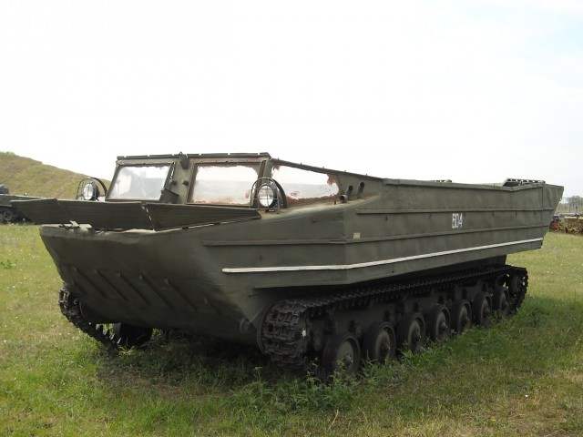
Tracked amphibious Transporter K-61
In our country in 1919 — 1920 at the Izhora plant in St. Petersburg was developed the project of amphibious tank called “the Ship AM”.
In 1932 on the basis of purchased in the UK light amphibious tank “Vickers-Carden-Lloyd” in the Soviet Union developed a prototype of amphibious tank T-33, which differed little from the English prototype After T-33 at the Leningrad plant named after Voroshilov created a prototype amphibious tank T-37.
According to test results at plant No. 37 under the supervision of N. N. Kozyrev, has developed its improved version — amphibious tank T-37A, which has retained the chassis of the T-37, but in the layout used the successful solution of the T-41, was developed by company T-37A was produced commercially for several years and was used by the red Army.
Military exercises and participation in local combat operations have revealed the main shortcomings of Russian amphibious tanks.
— weak arms and a booking does not allow them to provide effective fire support to landed troops on the retention and expansion of the bridgehead,
— body had a non-optimal hydrodynamic shape and small reserve of buoyancy, which affected their rate of movement in the water.
Simultaneously with the work on improving the design of floating tanks, research institutions and army inventors proposed and tested a variety of devices that allow to overcome water obstacles by swimming on the bottom of the main tanks of the red Army at the time — BT-5, BT-7 and T-26 One of the most famous inventors of these devices were tanker far Eastern Anatoly Kravtsev the Second world war confirmed the relevance and necessity of the works to equip troops with the means to overcome water obstacles and the need for their further improvement.
Analyzing the rich experience of the recently concluded war, And f Kravtsev clearly saw the shortcomings of the existing crossing equipment Existing equipment pinned down the advancing troops at the water, disrupting the coherence of their tactical cooperation Crossing means could lead the loading of troops directly from the cutoff of water Transport to deliver them to the intended point of overcoming water obstacles, had limited throughput, and is often the last segment of the path crossing equipment had to be transferred to the personnel on hand that did not contribute to the secrecy and suddenness of the operation Transported these funds are mostly unassembled, and their embattled was very time consuming For the successful solution of standing in front of a Soviet Army need was not the upgrading of existing engineering means of overcoming water barriers, and the creation of a fundamentally new machines, take into account the increased requirements for mobility of troops.
The main ideas embodied in the new machine, was autonomy, high cross in off-road conditions and in places out to the water barrier, the rational use of the power plant on land and in water, able to produce loading and unloading equipment and personnel as the cutoff of water and at a distance from him, She was not supposed to require special engineering training places of loading and unloading of people and equipment fast to transfer crew from marching position in fighting the Acceleration of loading and unloading operations should provide them with mechanization with the use of the power plant facility Machine must be confident to overcome the obstacles existing in the offensive zone of the troops, and to secure the crossing of the fixed assets infantry division All these considerations formed the basis of the technical specifications for transport means crossing the proposed A f by Krovavym to develop In further work, these requirements were refined, which expanded the technical capabilities of the new machine, So its capacity for water was increased to five tons, the number of transported personnel to 40 — 50 people in the list of cars included “Studebaker” standard guns infantry division began to cross with the expectation and ammunition.
The first study Anatoly Fedorovich produced in 1945 the search for the best layout, which depended on the implementation of formulated tactical and technical characteristics, it was a long and painful the longer I analyzed the suspension of the future car designer, the more favoured a tracked vehicle.
Using the chassis of tanks were impractical due to the large mass seemed More promising use of tracked artillery tractor of the Mytishchi plant No. 40 recently released.
Attracted large-scale production of the tractor, good clarity of many of its components, proven It is possible to use the basic units of tractor engine, transmission, chassis units to build the machine to the maximum extent, meet the designed performance characteristics.
On the overall layout of any tracked vehicle has a significant impact requirement to ensure railway transport Conveyor capable of transporting a 18-ton two-axle platform with a width between the sides of 2.74 m In theory of controllability of the tracked vehicles the optimum ratio of length of the support surface caterpillars of the track lies in the range of 1.8 — 2.
After considering various options a designer has established in the opinion that to cross water barriers of heavy artillery systems and trucks floating conveyor must have a maximum width of the machine 3.15 m cargo bed length less than 7 m, which was 90 percent of the total length of the machine.
This has resulted in a layout option in which MTO was located under the center of loading platform All further layout study was conducted by Anatoly Fedorovich in this direction.
The initiative is A f Kravtsev to create floating crawler Transporter found support from the Armed Forces, and to continue work on this topic by the order of the Deputy Minister of the Armed Forces of the USSR No. 093 dated December 3, 1947 was established the Special design Bureau of engineering troops (OKB IV), which has started the detailed design of the floating conveyor.
As the Foundation of an all-welded semi-displacement hull designer used a frame of two longitudinal box beams made of sheet steel connected by front and rear transverse relationship and a family of torsion beams To the wall beams of the frame attached to the chassis components To stiffen the body he was supported by four frames, box section made from 2 mm sheet steel fore end of the hull frame formed from stamped elements his aft was welded to the rack two box sections to stiffen the walls and fixing the flip side For covering Kravtsev chose a 1.25 mm sheet steel To increase rigidity and strength of the sheathing on the outside to it was welded to U-shaped profiles.
For covering bottoms used 2 mm sheet steel, and only in the bow, where the probability of hitting the drift wood, coastal stumps and rocks above, its thickness increased to 3 mm Inside of the hull plating was reinforced by the transverse profiles To the floor of the loading platform has also laid down stringent conditions, given its above-mentioned sizes and the contribution to the total mass of the case, the Task was complicated by the variety of vehicles and goods carried by the conveyor.
As when creating any machine is not left unattended safety requirements of the crew conveyor, taking on Board the self-propelled machinery, given that in many cases this operation will be carried out at night with observance of conditions of blackout.
To receive on Board the Transporter vehicles and artillery systems, creating a concentrated load on the platform, it has established two powerful beams dural flooring width 0,68 m box-shaped cross section with a developed vertical walls that limit lateral movement and prosowski movement of equipment on the side of the upper branch of the control beam had a high emphasis On each beam was located at the six mooring earrings, which were fastened with zip ties, locking the cargo Motor closed easily removable hood the Rest of the cargo platform plywood closed lids and grates In the Central part of the platform above the radiator was intake grill, but the output grid was located closer to the compartment between the beams of the flooring and the side of the conveyor.
To transport the gun crew aft platform seat set, put in the direction of the lateral side, so as not to interfere with loading and unloading equipment, which was produced through the hinged rear aluminum Board as the welding of aluminum constructions at that time were not sufficiently developed industry, the connection is performed by riveting duralumin Creating the design of the rear wall, And f Kravtsev was faced with another problem to be addressed — ensuring the tightness of the joint with a length of more than 4 m After a series of experiments it was found a reliable solution at the rear edge of the platform housed a public profile with sponge rubber, I was pressed against the locks that hold the rear Board, round rod, fixed on the contour of the joint on the folding Board.
The office to place in the beginning of a long loading platform failed, so I stopped on a variant when the crew seats were located directly behind the abutments of the beams of the flooring the body of the car ZIS-151, mounted on the platform, hanging over the heads of the crew of the floating conveyor To create a crew Transporter normal working conditions and protect it from precipitation and mud at the upper part of the frame of the glazing of the offices were installed quick-detachable canvas awning that had several mounting options.
No less difficult was the choice of the power plant conveyor Motor capacity of 150 l was not, and the serial artillery tractors were used American engines the GMC-4-71, supplied under lend-lease Yaroslavl automobile plant ready for serial production which was translated into the metric system copies this engine under the brand name YAMZ-204 On the prototype machines were installed GMC-4-71 in the expectation that by the end of the test will appear on the Yaroslavl copy Another important problem associated with the power plant, there was a low level of noise in the terrain to stealth of movement of the conveyor, in a combat zone, and especially afloat on the conveyor So the exhaust gases were performed in the water through the pipe located above the caterpillar.
To ensure the normal operation of the engine and transmission, required to securely attach the power unit to the casing made of sheet metal the Most suitable place for installation of the attachment was torsion beam, but transmitting load from the torsion on the non-rigid case, they had a significant deformation, which could lead to the destruction of the motor to compensate For deformations in all three points of attachment of the engine to the joists installed powerful rubber dampers.
Given the poor exit conditions from water to land was necessary to the engine to overcome the inclines up to 40 degrees In OKB IV conducted a detailed analysis of the lubrication system of the engine, investigated the conditions of the fence the oil from the crankcase at angles of up to 45 degrees According to the analysis performed revision of the lubrication system of the engine and tipped its longitudinal axis by two degrees down as a result have achieved sustainable operation of the engine on climbs to 42 degrees.
Mutual alignment of the units of the power transmission in a non-rigid body experiencing large dynamic loads, was another task, which successfully managed the designers of OKB IVE solved the Problem, using the powertrain propeller shaft with splined connection.
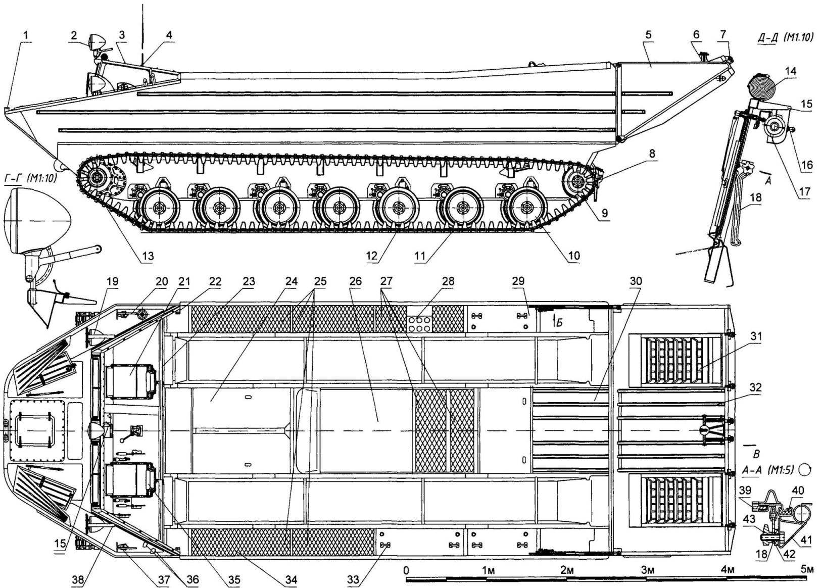
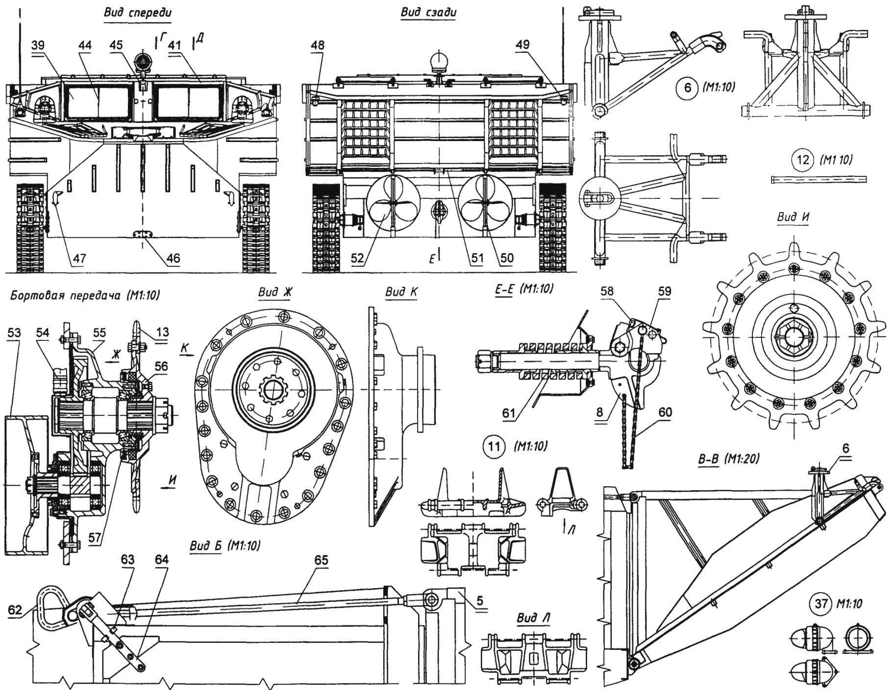
Tracked amphibious Transporter K-61:
1 — clamp, 2 — headlight-floodlight, 3 — button fastening, canvas tent, 4 — antenna radio R-113,5 flip vodozemci Board, 6 — pin,7 — axis of the folding ramp; 8 — tow hook, 9 — Lenivets, 10 — track roller, 11 track, 12 — thumb 13 — the crown leading zubchatki, 14 — canvas tent cabins, 15 — bracket wiper, 16 — a wiper switch, a 17 — electric 18 — bracket peredney glass, 19 — headlight FG-1A2, 20 — marker lamp OKB EVE with a green filter, a 21 — seat of the commander of the conveyor 22 — mounting bracket pipe awning in the service position 23 — tube tent (in transport position), 24 middle panel, 25 — weekend grid, 26 — hood, 27 — fence lattice, 28 — housing exhaust system, a 29 — seat cover, 30 — cabin aft, a 31 — edge, 32 — stiffener, 33 — handle, seat, 34 — Bay batteries, 35 — pillow seat back of the driver, a 36 — output connections bilge system 37,48 and 49 marker lights OKB EVE with a red filter; 38 — fencing of the lights, 39 — windscreen, 40 — spongy rubber, a 41 — frame front glass 42 — gasket 43 — wheel, 44 — wiper brush holder, 45 — bracket lights-floodlight; 46 — cover of the hatch for draining oil from the main gear, 47 front tow hook, 50 rudder 51 — torsion offensive side; 52 — thruster, 53 — brake drum, 54 — Sapun; 55 — Carter side of the transmission, 56 — a hub of leading zubchatki, 57 — labyrinth seal, 58 — dog clips, towbar, 59 — buccino latch on hook, 60 hook chain, 61 — spring 62 — handle with traction flip side, 63 — unit, 64 — arm-latch, 65 — pull folding walls
In the described period, the power unit a Prime mover was made in the form of a monoblock, combining motor and gear box PTO for the drive of propellers and winches and pumps of the bilge system should be made directly with the output shaft of the transmission For tracked amphibious Transporter has developed a new Assembly — junction box from which power is transmitted by cardan shafts on the tracks, screws, winch, bilge pumps system.
It would seem that the creation of a floating suspension of the conveyor, which was used the finished and tested nodes Mytishchi Prime mover, shall not create any difficulties, but they arise as soon as the designers of OKB IVE started the detailed design of caterpillar tracks, the First problem was the fact that the total mass of the tractor load does not exceed 8.5 tonnes From the floating Transporter the figure was in the range of 12.5 — 14.5 tons in order to keep the load on the torsion bars and road wheels, it was necessary to increase their number from ten in the truck to the conveyor 14. It is provided with continuous movement of the preservation of the maximum loads at the same level on all the chassis components, while increasing overall vehicle weight by 40 percent increase in the number of rinks has allowed to increase the length of the support surface caterpillars to 4.6 m — maximum values for the track width of 2.3 m when satisfactory and turning tracked vehicles on soft soil, the Introduction of third rollers for the upper branch is not saved from falling caterpillars when turning on soft ground To prevent this from happening, required an increase in the dynamic travel of the carrier roller in twice with 70 mm for tractor up to 150 — 170 mm — Transporter the Developers of the tractor was considered technically impossible without increasing the dynamic stroke to create a 14-Katko-first suspension, excluding the decay tracks, referring to the experimental data obtained by the tankers in the course of extensive research.
Many technical solutions when creating a tracked amphibious Transporter was made after a comprehensive analysis of foreign and domestic experience of creation of amphibious vehicles is No exception to this practice, and hydraulic propulsion.
After a comprehensive analysis chose to install with two screws in the individual conduits acceptable cross-section with a moderate velocity of water flow In the event of loss of flow from the torsion beams was less than in other embodiments, the use of power was more rational, and the installation of the towing device was simple at the same time ensured the control of the conveyor on water at stop and low speed.
One of the most difficult units of new conveyor — welded displacement body of impressive size that had to be done from sheet steel To build the hull on the second armored repair plant (2nd BTRZ) fabricated welding bench, which became the cradle of the future Transporter compliance with the developed technology allowed to weld the frame with leads that met the tolerances specified in the design documentation the Most complex process step in the Assembly of the hull was welding a 1.25-mm cladding and profiles of stiffness to it it had to improve welding equipment and conduct additional training of welders Not less complex was the welding of the tunnels bring water to the propellers.
April 30, 1948, four months and twenty days since the creation of EDO EVE, in the Assembly hall of the 2nd BTRZ stood freshly painted first prototype of a fundamentally new transport machine conveyor subjected to factory testing, which eliminated the identified design and manufacturing defects.
During the tests at the turning bracket sloth is deformed, and the tire deviated from the plane of rotation of the chassis After the reinforcement of the place of embedment of the bracket during field and military trials this defect is not repeated After loading onto the platform of the Transporter vehicle, the ZIS-151, equipped with a winch, the tailgate would not close, so had the front wheels under the car to put the boards To eliminate this defect in subsequent beams the height of the flooring in the center of the front wheels has been increased by 40 mm.
Another defect identified during factory tests, were insufficient stiffness of the pedestal main gear Rigidity of the pedestal is increased, and to mitigate the loads on the main gear began to mount on rubber shock absorbers.
Suspension did not work when turning on soft ground caterpillar dropped from sloth and damaged rubber band Defect was serious — the Transporter couldn’t work on soft and loose soils.
The main reason was the fact that when the emergency arose slack due to the large length of the track chains and small static moves rollers. To pick up the slack mechanical tension was not possible because the caterpillars were still sagging between the supporting rollers and on the descending and ascending branches of the lower part of the caterpillar Under critical conditions, the output of the track roller out of engagement with the ridges of the truck To reduce sagging of the upper branch of the caterpillars was introduced supporting rail, and in order to completely eliminate shedding of the caterpillar, subsequently developed a full metal sloth oval cross section, which is prevented from engagement with the ridges of the Shoe.
After the completion of factory testing the Transporter by order of the chief of Engineering troops transferred in the summer of 1948 for field trials, held at the Pirogov reservoir in Moscow and on the river Dniester. In these tests the conveyor was used to ferry various artillery systems, including case tools.
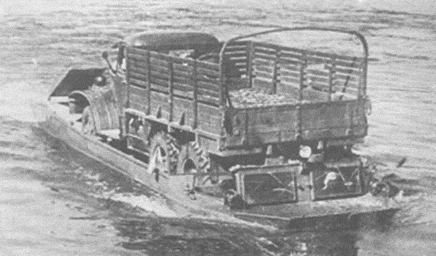
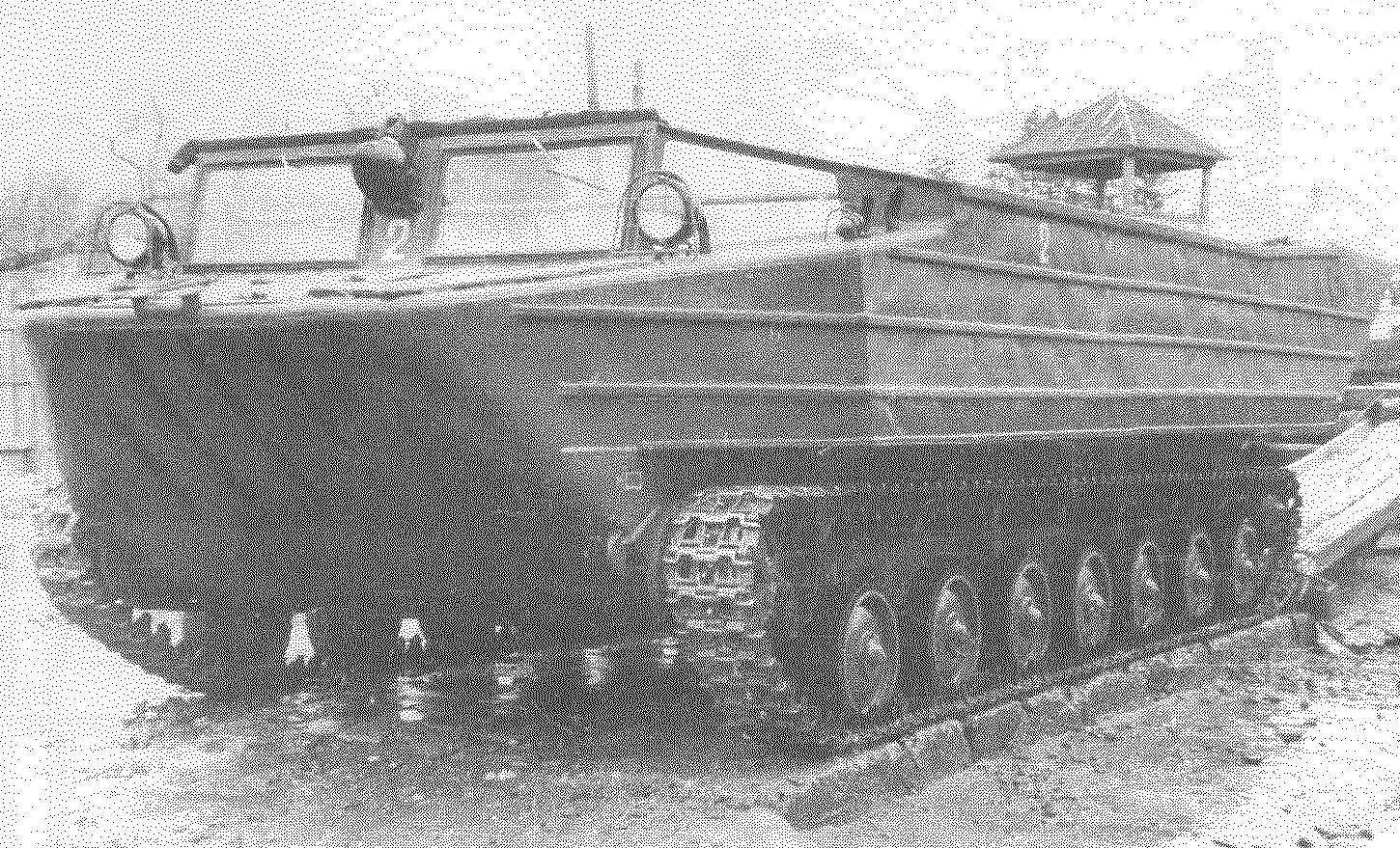
Crossing the Dnieper river the ZIS-151 on the conveyor belt K-61
During the terminal five-ton cargo found that when you exit the steep Bank height at the stern was only about 100 mm in the rolling conveyor back or approach, even small waves could result in flooding of the vessels To eliminate this danger mounted removable bulwark with a height of 250 mm, which was not the best solution Therefore, the development of the case for the second prototype floating crawler Transporter were implemented constructive solutions which allowed to completely eliminate the risk of flooding during the approach to the steep Bank of the river with a strong current It is possible to increase the displacement of boats is 36 percent After completion of tests the State Commission in its opinion noted.
“Recommend designed by OKB Engineering Committee of the Land forces of the sample tracked amphibious Transporter K-61 to speedy military trials, after the elimination of defects, noted in the punch list”.
Military tests of K-61 was conducted on the orders of the Commander of Land forces in the autumn of 1948 under the chairmanship of Colonel N P Pukhov in the Odessa military district.
Scientific and technical Council of Engineering troops in September 1948 approved the creation of the Commission on military trials on the adoption of the conveyor K-61 in service with the Soviet Army and recognized the need to introduce them to the staff of special units of the divisional and corps of engineering special engineering parts and floating parts of machinery of the Reserve of the Supreme Command.
The Ministry of the Armed Forces of the USSR adopted a decision on the manufacturing industry of prototypes conveyor K-61 to determine whether their serial production and additional testing.
At the Stalingrad tractor plant in may — June 1949 have produced three pre-series conveyor belt K-61, scheduled for mass production-Two of them participated in additional testing the Commission on carrying out of additional tests was headed by the commander of the Leningrad military district the General-Colonel M P Kovalev.
Tracked amphibious Transporter K-61 was adopted by the Soviet Army in may of 1950, the production decision of the government instructed Kryukov railway car building works.
For the Kriukov plant, development of production of tracked amphibious Transporter was extremely challenging, but in April and may 1952, the factory completed the manufacture of two main series of samples of K-61 were produced by the factory until 1958, when its production was transferred to Izhevsk plant “Strommashina” the First two floating conveyor yizhivtsi presented to the customer on 31 December 1959 production of the K-61 in Izhevsk continued until 1965.
The design of the K-61 is a classic, marked the beginning of the whole direction of domestic engineering technique For creating a floating conveyor Anatoly Fedorovich Kravtsev in 1959 was awarded the State prize.
Basic data of K-61
Weight of conveyor kg……………9500
The capacity of the machine, kg
on land…………………………………..3000
on the water…………………………………..5000
A diesel engine……………………Yaz-204ВКр
Maximum
motor power, l…………135
Crew…………………………….2
Download options
the number of soldiers…………………………40
wounded on stretchers…………….8
equipment gun
caliber up to 122 mm or 152 mm howitzer, or mortar to 160 mm or one car ZIS-151, ZIL-157 and GAZ-63, UAZ-69 Maximum speed, km/h
— on the highway…………………………….36
— on dirt roads…………25
— on the water (with load)……………….10
The biggest climbing angles, grad
— lifting without a load……………….42
— loaded………………………………25
— enter the water without load/ with ZIS-151 15/5
The reserve fuel
— by land, km………………………….170-260
— the water h…………………………….10
Recommend to read
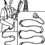 EXTENDER-SURVIVOR
Folding wire extension can peretiraetsya on the bends. To avoid this, you should wrap several layers of insulating PVC tape, slide a section of PVC conduit or rubber hose of suitable... … BEDROOM WARDROBE
The problem of rational use of residential space inevitably confronts everyone who possesses a small or Studio apartment. That's why we planned a makeshift wall, which, in addition to...
