Low-pressure, large-diameter pneumatic tires are excellent propulsion systems for all-terrain vehicles even in the most difficult road conditions. However, when they work with modern high‑speed engines, they require a significant reduction of angular velocities by means of the transmission and, as a result, an increase in the number of gear stages, as well as in the weight and overall dimensions of the driveline.
Every amateur designer arranges the transmission in their own way. Some even build it from several gearboxes, connecting them with chain drives, which makes the driveline bulky and unreliable in operation. Therefore, a compact gearbox with a high gear ratio is not only an important but also a necessary unit in the transmission of a pneumatic all‑terrain vehicle.
The magazine “Modelist‑Konstruktor” has covered gearboxes more than once (see, for example, No. 11’89), but in my opinion the published units do not fully provide the reduction in speed that is acceptable for low‑pressure tires.
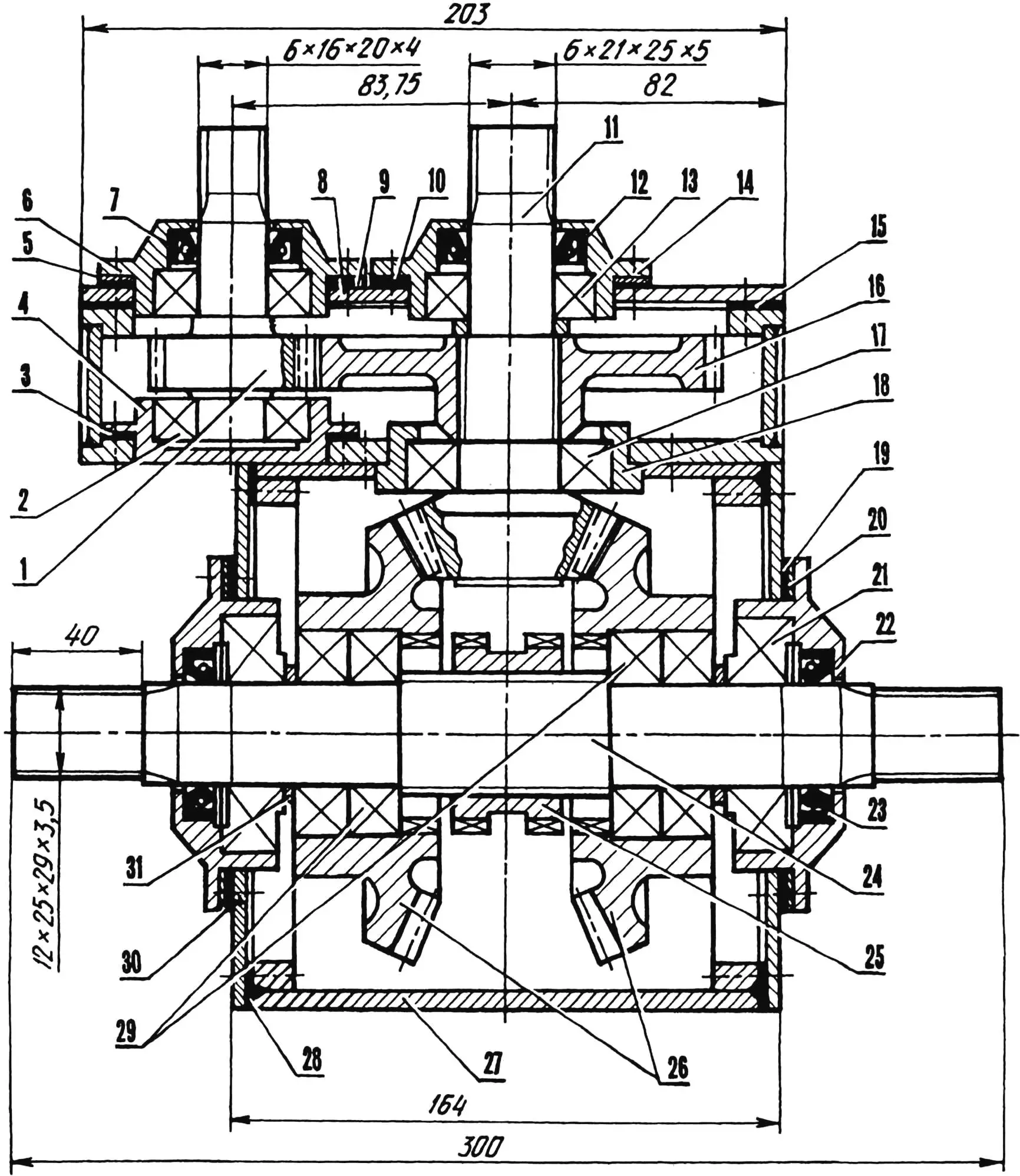
1 — driving shaft‑gear z1 of the first stage; 2 — bearing 204 (2 pcs.); 3 — rubber gasket 80x60x2 (2 pcs.); 4 — inner flange of bearing 204; 5 — pack of shims 80×60 (sheet steel s0.2…0.5); 6 — outer flange of bearing 204; 7 — oil seal 40x20x9; 8 — cover (steel sheet s6); 9 — rubber gasket 84x56x2; 10 — pack of shims 84×56 (sheet steel s0.2…0.5); 11 — driving shaft‑gear z3 of the second stage (PTO); 12 — oil seal 46x25x10; 13 — bearing 205; 14 — bearing 205 flange; 15 — gasket of the gearbox housing cover; 16 — driven gear z2 of the first stage; 17 — bearing 36206; 18 — bearing 36206 housing; 19 — rubber gasket 108x82x2 (2 pcs.); 20 — pack of shims 108×82 (sheet steel s0.2…0.5, 2 sets); 21 — bearing 7306 (2 pcs.); 22 — bearing 7306 flange (2 pcs.); 23 — oil seal 52x30x10 (2 pcs.); 24 — gearbox output shaft; 25 — reversing sleeve; 26 — driven gears z4 of the second stage; 27 — gearbox housing; 28 — housing wall gasket (2 pcs.); 29 — bearings 206 (4 pcs.); 30 — wall (steel sheet s6, 2 pcs.); 31 — spacer ring (2 pcs.)
I propose a technical design that shows the arrangement of a compact two‑stage reversing gearbox I have developed, which is small in size and designed to work even with a motorcycle engine. The basic data for selecting the gearbox gear ratio are given in Table 1. The list of standard parts is given in Table 2.
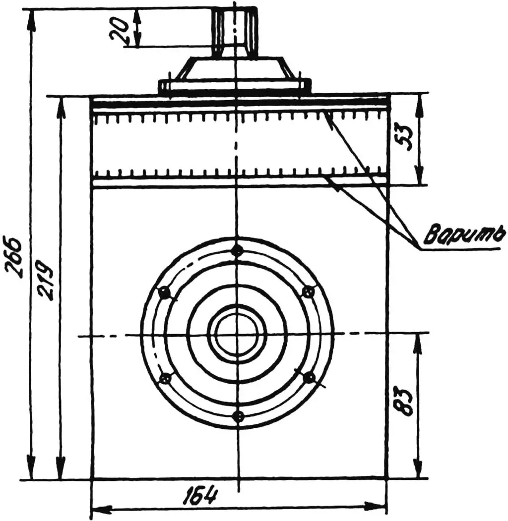
The gearbox housing is two‑section, made of 6–8‑mm‑thick steel sheet. All its walls are rectangular. Both sections are welded and connected to each other by four M10 bolts. Each bearing housing is fastened to the wall with six M6 screws. The gaskets under the bearing housings are made of oil‑resistant rubber, and the shims are made of 0.2–0.5‑mm‑thick sheet steel.
The gearbox driving shaft‑gear, machined from a single blank, is coupled via a clutch to the output shaft of the power unit gearbox. The gear ratio of the first stage can be changed depending on the diameter of the pneumatic tires. It is selected by the number of teeth in the mating pair of cylindrical spur gears — driven and driving. The driven gear is mounted on the shaft‑gear of the next stage, which acts as a power take‑off shaft (PTO) and can be used to drive a winch or other mechanisms.
The second stage of the gearbox consists of three straight‑toothed bevel gears. The driving shaft‑gear is in constant mesh with a pair of driven gears mounted on a common shaft. It is driven via a toothed sleeve that slides along the shaft splines. The sleeve can mesh with either of the driven gears or remain in a neutral position between them. The sleeve is shifted by a lever mounted on the gearbox housing and linked to a fork.
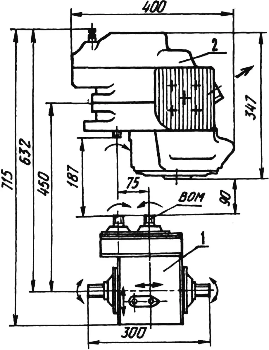
1 — gearbox; 2 — engine with gearbox
If the vehicle has no reverse gear because the transmission lacks the corresponding stage, the reverse function of the gearbox will provide it — and at the same speeds as when moving forward. Such a gearbox allows the drive to be located either at the front or at the rear of the pneumatic all‑terrain vehicle.
| Stage I, spur cylindrical, m = 2.5 | Stage II, spur bevel, mc = 3.5 | ig = iI × iII | ||||
|---|---|---|---|---|---|---|
| Da2 Da1 | Z2 Z1 | iI | Z4 Z3 | iII | ||
| 122.5 55 | 48 19 | 2.526 | 39 17 | 2.294 | 5.795 6.747 | |
| 127.5 50 | 50 17 | 2.291 | ||||
| 132.5 45 | 52 15 | 3.466 | 7.951 8.685 | |||
| 135 42.5 | 53 14 | 3.786 | ||||
The gearbox design allows for routine maintenance and, when necessary, repair and replacement of parts. Backlash in the gear mesh can be eliminated by removing one or more shims from under the bearing housings.
| Pos. | Name | Qty |
|---|---|---|
| Bearings | ||
| 2 | 204 GOST 8338-75 | 2 |
| 13 | 205 GOST 8338-75 | 1 |
| 29 | 206 GOST 8338-75 | 4 |
| 17 | 36206 GOST 831-75 | 1 |
| 21 | 7306 GOST 331-71 | 2 |
| Oil seals | ||
| 7 | 40x20x9 GOST 8752-701 | |
| 12 | 46x25x10 GOST 8752-701 | 1 |
| 23 | 52x30x10 GOST 8752-701 | 2 |
The gearbox can be manufactured in a workshop equipped with gear‑cutting machines and equipment for surface hardening of wear parts.
“Modelist‑Konstruktor” No. 8’2001, T. BURKOV, Vakhtan settlement, Nizhny Novgorod region
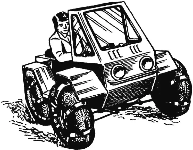
A motorcycle and a car are different machines. First and foremost, in terms of comfort. But can the advantages of two-wheeled transport be combined with the convenience of a passenger car? It turns out they can. Such two-wheeled machines—autorollers or motocars—are sometimes seen on the streets. We suggest you build one of these designs yourself.
This vehicle is a scooter with an engine of about 50 cm³ displacement, which, unlike traditional two-wheelers, has a light plastic body with a folding top, a seat almost like in a car, and two additional small wheels that can be raised and lowered like landing gear on an aircraft.
Let’s get to work. We’ll start with the frame. Obviously, you can’t build it without a welding set. You’ll need steel tubes with an outside diameter of 34 mm and wall thickness of 2.5 mm, tubes 22 mm in diameter (same wall thickness), and a front telescopic fork from any moped or scooter. The frame is designed for wheels from a Riga-built mini-moped, but scooter wheels will work too. You’ll also need sheet steel about 2.5 mm thick.
First, draw the frame full size. This will let you cut the blanks correctly and accurately from the drawing and finally fix the main dimensions of the parts.
As the drawings show, the autoroller frame is backbone-type and consists of a welded two-tube L-shaped spine that also acts as the rear wheel fork. To each tube, 4 mm thick steel plates with longitudinal slots for the axle are welded. We recommend cutting the slots after the plates are fitted—this helps get the work more accurate.
Now join the rear wheel to the frame tubes, tighten the axle nuts firmly, and mark where the bends will be. For a small bend you don’t need to pack the tube with sand—a tube bender is enough. After fitting, the tubes are welded at two or three points.
Next, fit the wheel in the front fork and fix the fork to the floor with wooden battens in the position shown. In the same way, set the frame spine with the rear wheel. Temporarily secure the spine to the steering column with soft copper wire. Check the wheel alignment carefully—they must lie in one plane. If correct, tack the spine to the steering column in two or three places. After final fitting, weld all joints fully. At the front, the spine-to-column joint is reinforced with gussets cut from 2.5 mm steel sheet.
The rear engine mounting bracket is cut and bent from 3 mm sheet steel. Do this in place: first cut a cardboard template and only after fitting make the metal blank. Fit the front bracket the same way.
After machining, attach the bracket to the engine and fix it on the frame with wire. Alignment must be checked again—the cylinder axis must lie in the frame’s plane of symmetry, and the carburetor platform must be level. After tacking the brackets, do a final check and complete the welding with the engine removed.
The frame base is ready. Add the cross tube that serves as the pivot for the extra wheels and small pads for the driver’s seat. The frame is then fully assembled.
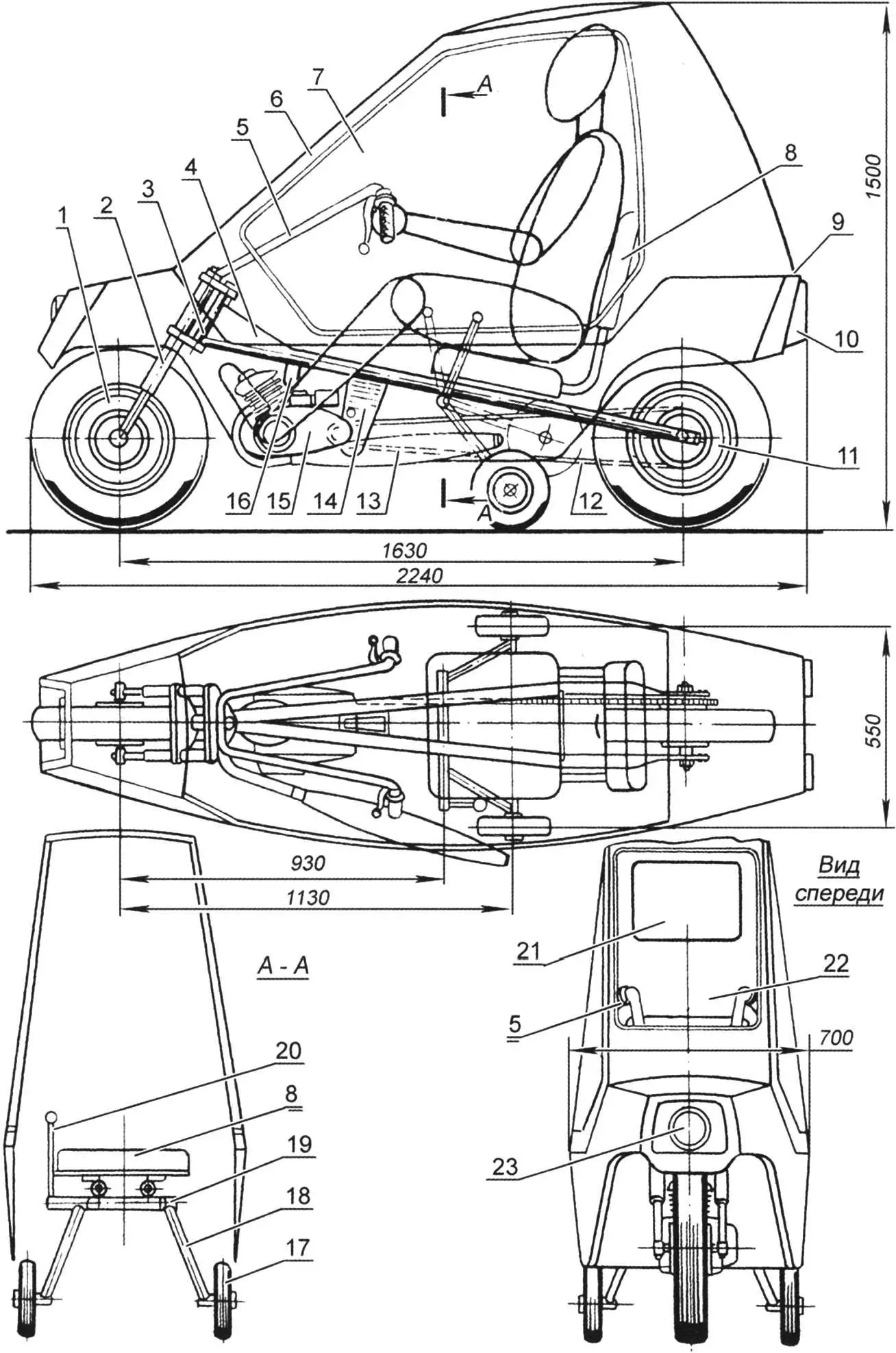
1 – front wheel (from mini-moped or scooter); 2 – front wheel fork (from any moped); 3 – frame steering column; 4 – reinforcing gusset from 2.5 mm steel sheet; 5 – handlebar (from mini-moped); 6 – folding glazed cab – “canopy”; 7 – block “glass” (Mylar film); 8 – driver’s seat (metal chair top, padded with foam and vinyl); 9 – hinge of folding cab (“canopy”); 10 – rear lights and stop lights (from motorcycle or scooter); 11 – rear wheel (from mini-moped or scooter); 12 – bushed roller chain (from two standard moped chains); 13 – muffler (from any moped); 14 – rear engine bracket (bent from 3 mm steel sheet); 15 – engine (Sh-58 or Sh-62 type); 16 – front engine bracket (bent from 3 mm steel strip); 17 – side support wheel; 18 – chassis strut (22 mm tube); 19 – support wheel pivot; 20 – chassis wheel raise/lower lever; 21 – rear window (Mylar film); 22 – front window (Mylar film); 23 – front headlight (from any moped)
For the extra wheels’ axle, choose a tube whose outside diameter allows it to rotate freely in the pivot. If you can’t find one, use a smaller tube or rod and compensate the gap with rings cut from plastic hose—they work well as plain bearings.
The chassis strut is made from 22 mm outside diameter steel tube. Weld a bushing to one end and a turned steel axle to the other. On the left strut, weld a short 10 mm steel rod with a thread for a plastic handle. This is the chassis control lever.
The extra wheels must lock reliably in both extended and retracted positions. The mechanism is straightforward; we suggest designing it yourself.
Chassis wheels can be from a children’s bicycle. Prefer rubber “balloon” or solid-rubber (not plastic) tires up to 200 mm in diameter.
The autoroller fuel tank is a 5 litre plastic or aluminium can. Fit a standard motorcycle fuel tap with sediment bowl and mount it at the rear of the body. Drill a vent hole in the can cap.
The body is plastic. The structure is built from 20×20 mm wooden battens.
The lower part of the body is like a small boat hull. Assemble the transverse frames from battens, then add the longitudinal battens per the drawing. Then skin the frame. Kitchen furniture plastic (sold in hardware stores) is a good option. Use epoxy for gluing the frame and skin. If you can’t find plastic, thin plywood or hardboard up to 3 mm is acceptable, or other options.
The upper part is built similarly. Glazing is transparent film of the kind used for model aircraft. Make window frames from 10×20 mm battens with spacers. Place the frame on the film, cut with a 20 mm margin, fold the film over and glue to the frame with BF-2 adhesive. Iron the joint with the iron set to “silk”. Then screw the frame into the window opening.
The window may not look perfect at first—Mylar is stiff and hard to tension. Use the iron set to “cotton” or “linen” and iron the film; it will tighten and flatten.
Final finishing is simple. With plastic skin, fill joints with epoxy filler (epoxy glue and talc) and paint with nitro primer then nitro enamel. With plywood or hardboard, level with filler, then cover with a layer of glass cloth and epoxy and paint.
Pay special attention to the controls. They are much like a moped’s. On the handlebar (from a Riga mini-moped) fit the throttle, front brake lever (right), and clutch lever (left). If the engine has a manual gear selector, mount it on the left of the handlebar.
The engine starter needs modification. At minimum, reposition the kickstarter lever on the splined shaft so it’s easy to kick from the seat. Better is a cord starter: fit a pulley on the splined shaft with two or three turns of nylon cord, run the free end to a convenient spot for a left-hand pull, and add a T-handle.
The last control is the chassis raise/lower lever—best under the driver’s left hand. The brake pedal for the rear wheel goes under the right foot.
For the first runs, leave the cab (“canopy”) off. Sit comfortably (chassis extended), put the gear in neutral, and start the engine. After warm-up, move off in first, then second. Retract the chassis only when the autoroller feels stable. Operating the extra wheels will feel odd at first but is easy to learn.
When using the autoroller, remember the engine runs cooler than on a moped. Ensure the cylinder cooling opening in the body is in the front wheel well, directly opposite the cylinder, and larger than the cylinder. If cooling is insufficient and the engine overheats, consider forced cooling. It’s not hard: remove the right crankcase cover and fix aluminium blades for a centrifugal fan on the flywheel/generator rotor. Make an air duct from bent aluminium sheet or from cloth and epoxy on a foam former, filled with plasticine or non-hardening putty.
«Modelist-Konstruktor» No. 6’2014, I. YEVSTRATOV, engineer
Recommend to read
 “GRANDMA,” A LAMP
Currently, it has become fashionable household electrical lamps with shades. The publication describes this decoration to the lamp, which is easy to do it yourself from simple materials....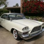 CHRYSLER 300D
Walter Chrysler, linking his life with autostructure and occupy considerable positions in well-known US companies, dreamed, however, of creating your own car. With the help of three...
