In large apartments and private houses, it is difficult in the evening and at night to walk along dark corridors or stairs and find the switch by touch to turn on the lighting.
There is also an alternative — to buy autonomous “soft light” fixtures; they can be installed anywhere convenient for the owner. However, besides undeniable advantages, such fixtures also have several significant drawbacks. First, they are powered by batteries that eventually wear out. Second, these devices use incandescent lamps as light sources, which (compared with LEDs) draw a relatively large current, have low efficiency, and a short service life.
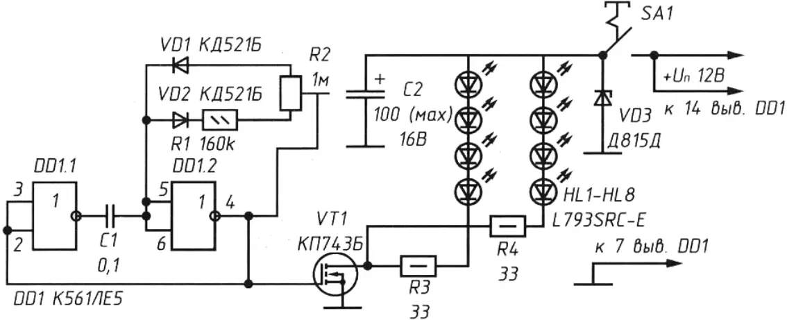
As a more economical alternative, a simple electronic device is proposed; its circuit is shown in the figure. It uses high-power LEDs as emitters, with the ability to adjust their brightness.
This low-voltage pulse DC power regulator allows you to change the brightness of high-power LEDs or the current in any active load. Compared with incandescent-based fixtures, this device avoids their drawbacks — LED lifetime corresponds to tens of thousands of hours, smooth adjustment of lighting power is provided, and the device can be powered both from autonomous sources (batteries, rechargeable batteries) and from a stabilized bench supply with a voltage of 6…15 V. Moreover, it is easy to build because the circuit contains only one CMOS IC, and even a hobbyist with limited experience can assemble it. Using LEDs also expands the capabilities of the device.
Thus, instead of the LEDs shown on the schematic, you can install LEDs of any emission color (blue, yellow, red, green, and others), and you can even use flashing LEDs — then this device can be successfully used as emergency indication for various processes, with brightness comparable to several miniature incandescent lamps (at 6.3…13.5 V), while lasting much longer.
The device is easy to adapt for smooth adjustment of interior lighting in a car, as well as instrument panel backlight brightness and many other suitable cases. To do this, it should be connected into the vehicle’s electrical circuit.
Operating principle
The device (see the schematic) uses a K561LE5 IC; both of its elements are connected as inverters. Each K561LE5 contains four identical elements. The rise and fall edges of the output pulse do not depend on the shape of the input signal. Elements DD1.1 and DD1.2 form a rectangular pulse generator with adjustable duty cycle.
Pulses from the output of the second element go to the gate of power MOSFET VT1; the load — two strings of four LEDs HL1 — HL8 — is connected in its circuit through limiting resistors R3 and R4. When there is no signal at the input, transistor VT1 has a high drain–source resistance (on the order of several MΩ), so the supply current is negligible — only a few µA (when the LEDs are off) and can reach up to 200 mA (depending on operating mode and the type of high-power LEDs used).
The transistor enters saturation when high-level pulses predominate at inverter DD1.2’s output. When low-level rectangular pulses predominate at the transistor switch input (this depends on the position of variable resistor R2, which sets the pulse duty cycle), the transistor turns off and the current through the LEDs decreases almost to zero.
The brightness of LEDs HL1 — HL8 changes depending on how often positive peaks appear at element DD1.2’s output. It is advisable to tie together all unused inputs of the remaining two elements of IC DD1 (pins 9, 10, 12, 13) and connect them to the “+” supply.
The transistor should be mounted on a heatsink — it is needed if the device runs continuously (24 hours a day).
The transistor switches at an almost constant frequency of 330 Hz. Using variable resistor R2 (preferably SPO-1BV), the pulse duty cycle can be adjusted so that the power delivered to the load varies from 5 to 95 % of the maximum. The LED glow is soft and flicker is not noticeable.
Assembly
A printed circuit board was not developed to save time. The parts were mounted on a prototyping board; leads were connected with jumpers made of MGTF wire with a cross-section of 0.6…0.8 mm.
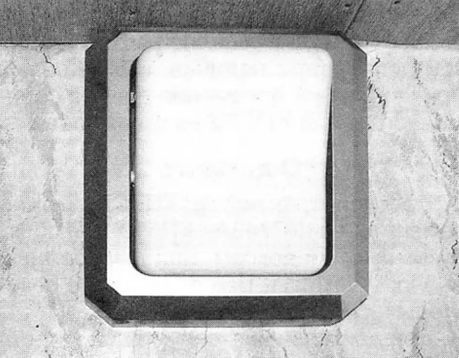
The industrial luminaire housing (photo on the cover) with the regulator inside is mounted in a convenient place and connected to conductors from a stationary supply through a compact connector (for example, RP10-5).
The knob of the variable resistor must be accessible for changing LED brightness when needed.
The device requires no alignment. At the junction of pins 1, 2, and 4 of IC DD1, it is convenient to check for pulses with an oscilloscope and, when moving the wiper of variable resistor R2, observe their duty cycle.
Parts and substitutions
Power MOSFET KP743B can be replaced with KP743A, KP510 with any letter suffix, or a foreign equivalent — IRF511. All fixed resistors are MLT-0.5.
During prolonged operation the resistors heat up to 40…50 °C. If 24/7 operation is expected, it is better to replace them with higher-power types rated for 1 W dissipation.
Capacitor C1 is type KM-6. Diodes VD1, VD2 can be replaced with KD521, KD522, D311, or similar with any letter suffix. Zener diode VD3 acts as a protective element against overvoltage from the supply (for example, when the device is installed in a car). In the given circuit it can be replaced with any other device that stabilizes at 12…13 V with a current of at least 25 mA; if the device is used in an apartment with a stabilized current source, VD3 should be omitted entirely.
Electrolytic capacitor C2 filters low-frequency ripple from the supply. It can be of any type (for example, K50-29).
Instead of K561LE5 you can use K561LA7 or K1564TL2, K561LN2 with schematic changes for the last two due to different pinout.
Variable resistor R2 (besides the recommended SPO-1BV) may be types SP3-12V, SP3-30V, or similar. Preferably they should have a linear resistance taper — the letter “V” in the designation.
Besides the LEDs indicated on the schematic, types RS276-143 and similar are acceptable. If the eight LEDs specified prove too bright, their number can be reduced without changing component values — thanks to the built-in adjustment you can always set the required luminous intensity. High-power LEDs L793SRC-E have a luminous intensity of 2.8 cd. This is incomparable to the once-popular indicator LED AL307BM (no more than 10 mcd), so in terms of luminous flux and thanks to adjustable brightness, in my opinion, this design will remain relevant in the future as well.
“Modelist-Konstruktor” No. 7’2011, A. KASHKAROV
Recommend to read
 “EIGHT” IN THE CIRCLE
Modern models of bikes full of new materials and technologies. But in most cases it touches the chassis, steering, powertrain. Virtually unchanged in design remains only a spoked wheel:... IN THE OFFICE — A STRANGER!
Depressing statistic of the attacks on the secrets and the assets of the firms, organizations, entrepreneurs (and ordinary citizens) makes it necessary to take appropriate...
