What is the microplane “Wasp” created by Kronstadt craftsmen? At first glance, it seems there is nothing new in it. A strut-braced high-wing monoplane, a scheme that has become the most popular among amateur designers. This very scheme was the basis for the microplanes “Leningradets” by N. Tatsiturny, “Malysh” by L. Komarov, “Sputnik” by V. Malyshev, and others. However, the similarity with them in the “Wasp” is purely external. The main difference is that the “Wasp” is built entirely of metal. This is the first all-metal aircraft created in amateur conditions. At the same time, it can serve as an example of a well-thought-out and “drawn” design, rationally composed and excellently technically executed, which is sorely lacking in almost all other amateur microplanes. After all, for our time, the culture of production is perhaps the main criterion for evaluation.
About other features of the “Wasp” aircraft is told by its “chief designer” — engineer Pyotr Lyavin.
— Actually, I was called the “chief designer” when I was unsuccessfully knocking on the doors of various institutions, seeking permission for further flights. And in terms of the volume of work, I did as much as my comrades, about whom the reader already knows. Perhaps more disappointments fell to my lot. But this is already from the realm of psychology, not technology.
In design, the “Wasp” is, figuratively speaking, the quintessence of everything we learned, first doing aeromodelling, then glider sports.
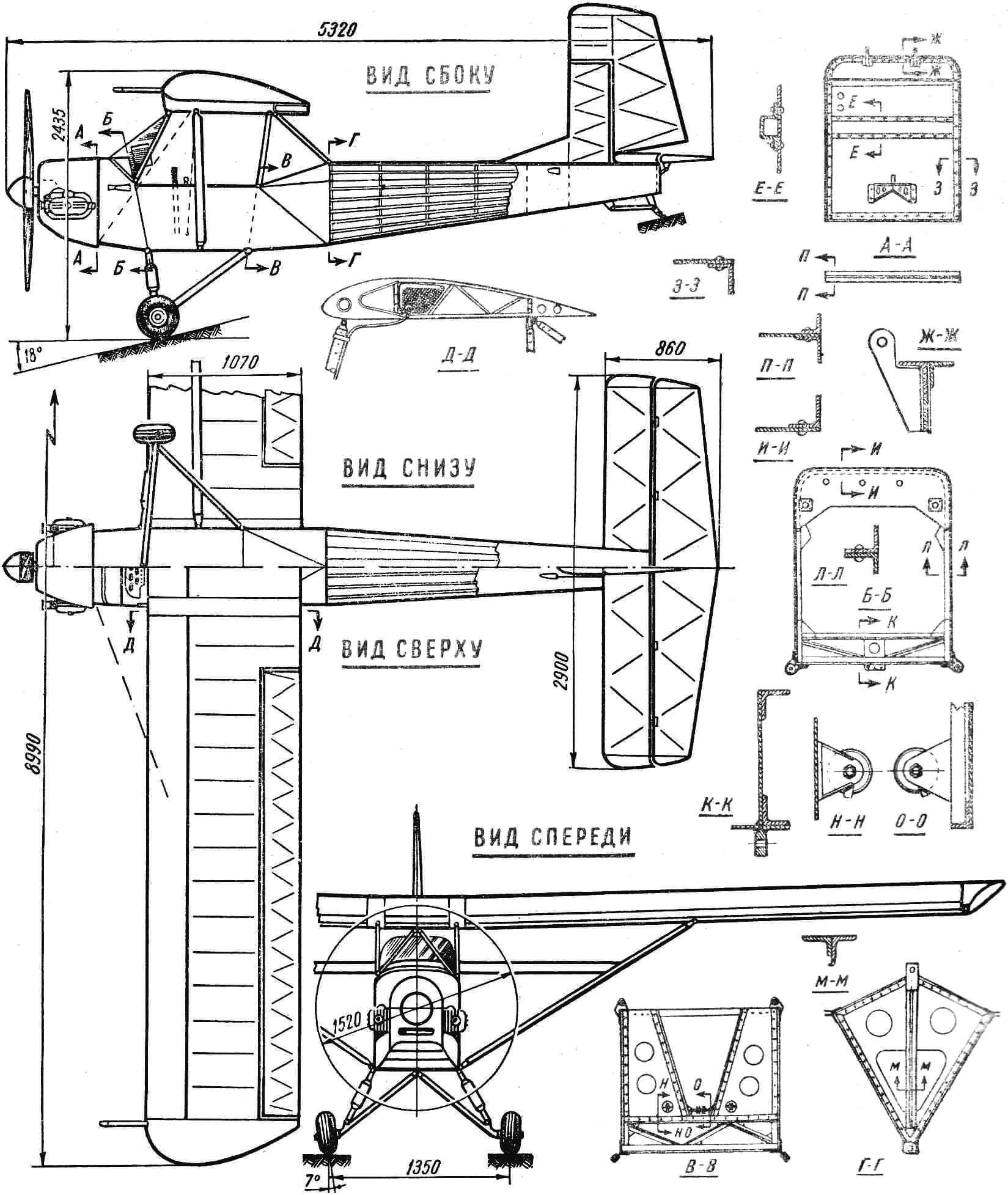
A feature of the “Wasp” aircraft is a detachable fuselage, consisting of two parts: the front (Fig. 2A), in which the pilot sits and the controls are located, and the rear (Fig. 2B), which is made together with the fin and carries the rudder and elevators. The rear part of the fuselage is joined to the front part at frame No. 4 with two bolts and two fittings. The front part has a rectangular cross-section, the rear part is made in the form of a prism tapering to the tail. This gives a noticeable weight advantage with high rigidity.
The basis of the front part of the fuselage is the cabin floor of a box structure, the diaphragms of which are truss parts assembled from pressed duralumin angles of grade D16T with a cross-section of 15X15X1.5 mm. The cabin sides are of truss construction, attached to the floor with steel gussets 2 mm thick. The cabin skin is made of duralumin 0.6 mm thick. The floor is sheathed with duralumin 1.2 mm thick on top and 0.8 mm — on the bottom.
The front part of the fuselage has 4 frames on which the landing gear, engine frame, centerplane struts and tail section mounting units are mounted. The basis of frame No. 1 is a duralumin sheet 1.5 mm thick, sheathed with duralumin angles 20X20X1.5 mm. It mounts the engine frame units, auxiliary engine equipment, and rudder pedals. At the same time, frame No. 1 serves as a fire barrier. Frame No. 2 is a closed contour, riveted into a T-section and reinforced from above with a wide gusset, on which shock absorbers for suspending the instrument block are mounted. Frame No. 3 is assembled from pressed duralumin angles 15X15X1.5 mm, fastened with two enlarged trapezoidal gussets 1.5 mm thick. Holes Ø 100 mm and Ø 60 mm are made in them — for foot control cables. Brackets for rollers are installed opposite these holes. The basis of frame No. 4 is a duralumin sheet 1.2 mm thick, sheathed along the contour with pressed angles 15X15X1.5 mm. The pilot’s seat is made of two bent duralumin tubes Ø 20 mm. The seat frame is covered with canvas, which turns into an adjustable backrest (for a back parachute). The backrest straps are equipped with hooks that attach to the nodes on frame No. 3.
The instrument block, riveted from D16AT duralumin, is installed on frame No. 2. It houses an altimeter type KM, airspeed indicator US-250, variometer VR-10, compass V-3S-10, turn and slip indicator type VII and an electric tachometer. The canopy is made of 4 mm thick plexiglass and is fixed on the fairing with four bolts with anchor nuts.
The tail section of the fuselage consists of a power central truss (Fig. 2), two solid and four composite frames and corrugated duralumin skin. The central truss is made of bent profiles No. 1, 0.5 mm thick D16AT, fastened with gussets made of metal of the same grade 0.8 mm thick. The composite frames are made of two symmetrical parts that are attached to the vertical posts of the central truss. It goes to frame No. 5, ending with reinforced strut-angles 15X15X5 mm in size and a box to which the stabilizer and tail skid units are attached. The tail section skin is made of corrugated duralumin 0.5 mm thick and is reinforced with profiled struts of profile No. 2 made of the same material. The skin has two hatches — for mounting and inspecting the structure and controls during operation.
The fin is a truss structure, the basis of which is a spar of U-shaped cross-section, made of duralumin grade D16AT 1.0 mm thick and rigidly fixed on frame No. 5. The fin is equipped with a forefin made of duralumin sheet 0.5 mm thick. The fin skin is madapolam, coated four times with enamelite.
The engine frame is made of steel seamless tubes. The frame is welded, truss type, with a transverse connection (Fig. 2B). Bushings 4 are welded to the tubular struts 1, which have a diameter of 18 mm, into which rubber is placed for engine damping. The engine is mounted in the same way as on a motorcycle, with two through studs Ø 12 made of steel 45. The transverse connection is a tube Ø 16, to which all the main elements of the frame converge. The frame is attached to the fuselage at four points: at the top — to frame No. 1 using two struts 5; at the bottom — directly to the nodes fixed on the frame. Auxiliary struts 6 serve to transmit longitudinal force from the foot control pedals. In addition, the upper part of the engine is reinforced with two additional struts with individual damping according to a design similar to the main one.
The cowling consists of two parts: upper and lower. The lower one is assembled from L-shaped channels and sheathed with duralumin grade D16AT 0.8 mm thick. It is attached at 4 points to frame No. 1 on “fingers” and reinforced from the end of the engine frame with 2 M6 bolts. If necessary, the lower part of the cowling is easily removed, the upper part of the cowling is hinged, which provides good access to the engine. In the working position, the upper part of the cowling is fixed with five “Dzus” type locks.
The wing has a rectangular shape in plan. It consists of 3 parts — a centerplane and 2 consoles. It is installed at an angle of 5° 30′ to the construction horizontal of the fuselage and has a transverse V = 1°. The wing profile РШ — 15.5%, constant along the entire span.
The basis of the wing is a trough-section spar, which has shelves made of pressed duralumin angles with a cross-section of 20x20x2 mm and walls made of duralumin sheet 0.8 mm thick. The walls of the trailing edge of the wing are made of the same material. The main spar wall has a number of lightening holes, and at the attachment points of the nodes it is reinforced with two-millimeter pads made of duralumin grade D16T.
The power scheme of the wing includes the main spar, rib noses and skin made of duralumin grade D16AT 0.6 mm thick; up to the main spar — a rigid, closed-section box. Each console has 29 noses and 16 tails of ribs. The tails are of truss construction, riveted from duralumin strips 0.6 mm thick, bent into angles. The end and root tails are reinforced. The wing tip consists of two transverse diaphragms and is sheathed with duralumin grade D16T 0.5 mm thick. The wing attachment nodes are welded from sheet structural steel 1.5 mm thick, the strut attachment nodes are made of stainless steel 1.5 mm thick. The wing has no mechanization.

A — nose section of the fuselage, B — tail section of the fuselage, C — engine frame, D — landing gear, E — example of a control-line model design.
1 — main tubular struts, 2 — transverse connection, 3 — diagonal struts, 4 — bushings with damping inserts, 5 — struts for attaching the frame to frame No. 1, 6 — auxiliary struts.
The centerplane of the wing is reinforced with strut tails and a rear spar, made of pressed angles 15X15X1 mm and sheet duralumin grade D16AT 1 mm thick. There are 3 attachment points to the front part of the fuselage by means of 5 struts and 2 bracing wires and 4 attachment points with the consoles — 2 on each side. The gaps between the console and the centerplane are closed with duralumin strips 150 mm wide and 0.5 mm thick. A fuel tank with a capacity of 10 liters is fixed in the centerplane behind the main spar using 2 rubberized metal strips.
The ailerons have a constant chord (265 mm) and occupy the main part of the wing. Each of them is attached to the wing at 3 points. The ailerons have no weight compensation. They are made of sheet duralumin 0.5—0.6 mm thick. The aileron skin is madapolam, coated four times with enamelite. The relatively large area of the ailerons provides good controllability at low speeds. The wing struts are made of tube Ø 55X53 mm and crimped to a streamlined cross-sectional shape. For greater rigidity, the wing is reinforced with two cable bracing wires Ø 2.2 mm, running from the strut to the front part of the fuselage.
The stabilizer is solid, rectangular in shape, made in the form of a truss, the rigidity of which is ensured by a combination of the front spar and leading edge skin. The leading edge and ribs of the stabilizer are duralumin, 0.5 mm thick, the spar is made of the same material 1 mm thick. The stabilizer tips are made of PS-1 foam, the skin is madapolam.
The stabilizer is fixed in the tail section of the fuselage at 2 points and is reinforced with 2 tubular duralumin struts Ø 16 mm, allowing adjustment relative to the construction axis of the fuselage within ± 1°40′.
The elevator is of truss-strut construction, consists of a spar of U-shaped cross-section, ribs and trailing edge, end profiles, pads and gussets made of duralumin. Attachment to the stabilizer — at 5 points. Weight and aerodynamic compensation is absent. The skin is madapolam.
The rudder is a riveted truss structure, consisting of a spar of U-shaped cross-section, ribs and trailing edge. The contour of the upper part is made of foam. There is aerodynamic compensation. The skin is madapolam.
The landing gear consists of the main, two-post landing gear of the pyramid type and a tail skid. The landing gear has 4 rigid and 2 damping struts Ø 200 X 80 mm. As a damping device, struts from the Ka-15 helicopter are used with recharging of the air system to 36 kg/cm2. The rigid struts are made of steel tubes grade 15ХМ Ø 24X2. The tail skid is of box section, welded from steel 20. A wire pack is used as a shock absorber.
Control — normal scheme, with a stick and pedals. The control wiring is cable-operated, from the stick to two-arm rockers located in the wing consoles, and a two-arm rocker on frame No. 5 of the fuselage, from where the force is transmitted to the ailerons and elevator using rigid length-adjustable rods. The connections of the pedals with the rudder are with cables Ø 2.2 mm.
The power plant is a motorcycle engine M-61 with a power of 28 hp, which, through minor modifications, has been increased to 30.5 hp. To reduce weight, additional equipment has been removed from the engine. Instead of battery ignition, a magneto is installed, the drive of which is carried out from the camshaft by two gears with the same number of teeth. The magneto is installed in place of the generator.
The drive to the propeller is through a single-stage gearbox (i = 2.37), the gears of which are taken from the Zaporozhets car.
To compensate for the peak moments of the engine and smoother transmission of torque between the engine crankshaft and the primary shaft of the gearbox, a flywheel clutch is installed. It has driving and driven parts, the connection between which is carried out by 6 cylindrical springs located around the periphery. The secondary shaft of the gearbox, on which the propeller is located, is connected to the primary shaft by a pair of helical gears.
The propeller is wooden, Ø 1520 mm. The tank is made of sheet duralumin 0.8 mm thick, has internal partitions — diaphragms to prevent fuel foaming. From the sump, fuel flows to the float chambers of the carburetors through two durite tubes, as shown in figures 1 and 2.
FROM THE EDITORIAL BOARD
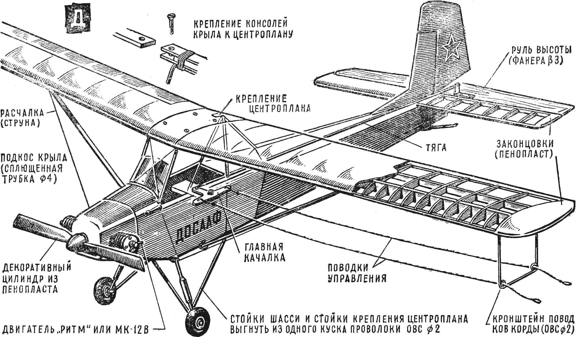
The “Wasp” aircraft can be recommended as a prototype for building a control-line or free-flight model-copy. It is better to put single-command equipment on the latter. The strut-braced monoplane “parasol” scheme, according to which the “Wasp” aircraft is built, allows making the model collapsible. An approximate model design is shown in Figure 2.
Since the model is intended for beginner modellers, engines from 1.5 to 2.5 cm3 should be installed on it. The optimal scale for a 1.5 cm3 engine is 1:12 (wing span — 750 mm), for a 2.5 cm3 engine — 1:10 (wing span — 899 mm)? Choosing such a scale facilitates recalculation for manufacturing model parts.
P. LYAVIN, Kronstadt
Recommend to read
 PLAYER POWERED WELLENREITER
Buying a player up to accommodate for his food during his frequent touring on-Board generator. As the adapter decided to use a homemade solid state rectifier. The implementation of the... “TURN THE HANDS!”
This call is present in many emails of designers bikes. "Somehow, browsing in the library of old magazines "M-K", I came across a design velocipede with manual transmission. From that...
