
The operating life of lead acid batteries largely depends on their proper operation. According to technical conditions, it is unacceptable to discharge one section below 1.7-1.8 V. Charging with a current significantly exceeding 1/10 of the nominal battery capacity, expressed in A*h, causes the electrolyte to boil. This happens, for example, when the relay regulator fails. As a result, the electrolyte level drops below normal, and its density increases. In addition, a high charging current reduces the service life of lead plates (especially positive ones). All these factors lead to premature failure of batteries.
How do you know if your battery is operating under adverse conditions? The problem is relatively easily solved using an autovoltmeter. This device differs from a conventional voltmeter in that it only shows within what limits the battery voltage is – “normal”, “overestimated”, “underestimated”.
We bring to our readers’ attention options for autovoltmeter circuits intended for installation on motorcycles and cars.
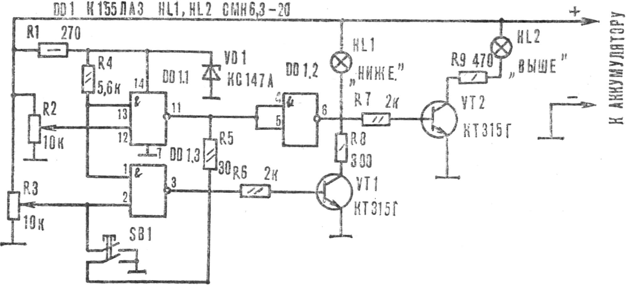
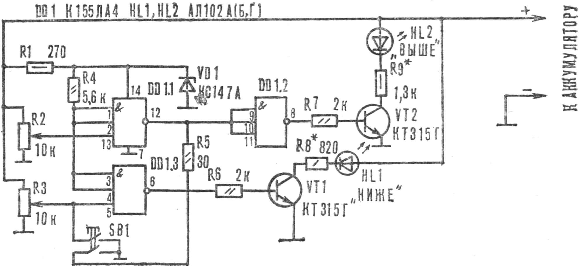
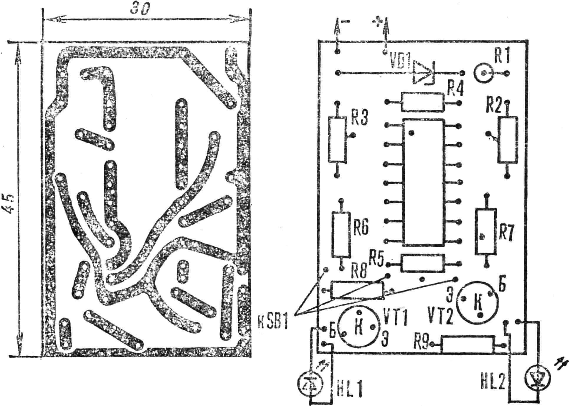
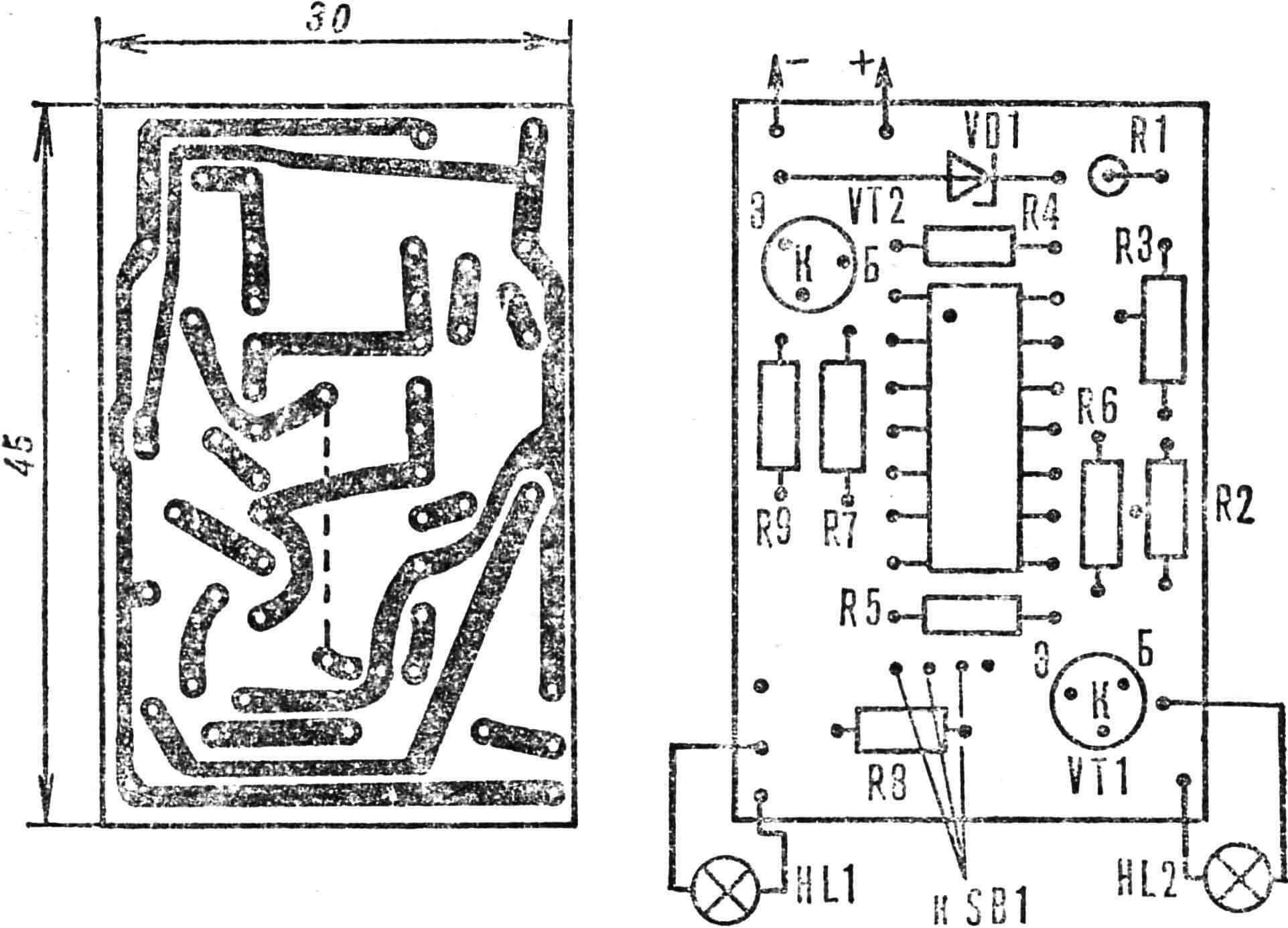
The principle of operation of all these devices is the same: when the voltage is below the threshold at the input of element DD1.3 (Fig. 1-3), connected to the resistor R3 motor (with its help, the lower measurement limit of the device is selected), there is a voltage of logical O, and at the other input there is a constant logical 1. At the same time, a high logical voltage level is also present at the output of the same element: transistor VT1 is open, and the indicator lamp (LED) is on. HL1 “Below normal.” When the voltage in the batteries is within normal limits, a logical level of 1 appears at the input of the element connected to the motor of resistor R3, and a logical 0 appears at the output of element DD1.3, and transistor VT1 closes. Lamp HL1 goes out.
The upper indication limit is set by turning the slider of resistor R2 to such a position that when the specified voltage limit is exceeded, a logical 1 appears at the input of the element DD1.1 associated with R2, a logical 0 appears at the output, and a logical 1 appears at the output of DD1.2. In this case, the transistor VT2 opens and the indicator lamp (LED) HL2 “Above normal” lights up.

While the voltage is within normal limits, not a single lamp lights up. However, the SB1 “Control” button will allow you to check the condition of the lamps and the operation of the device as a whole. When it is turned on, low logical voltage levels appear at the inputs of elements DD1.2 and DD1.3, and both lamps (LEDs) HL1, HL2 flash.
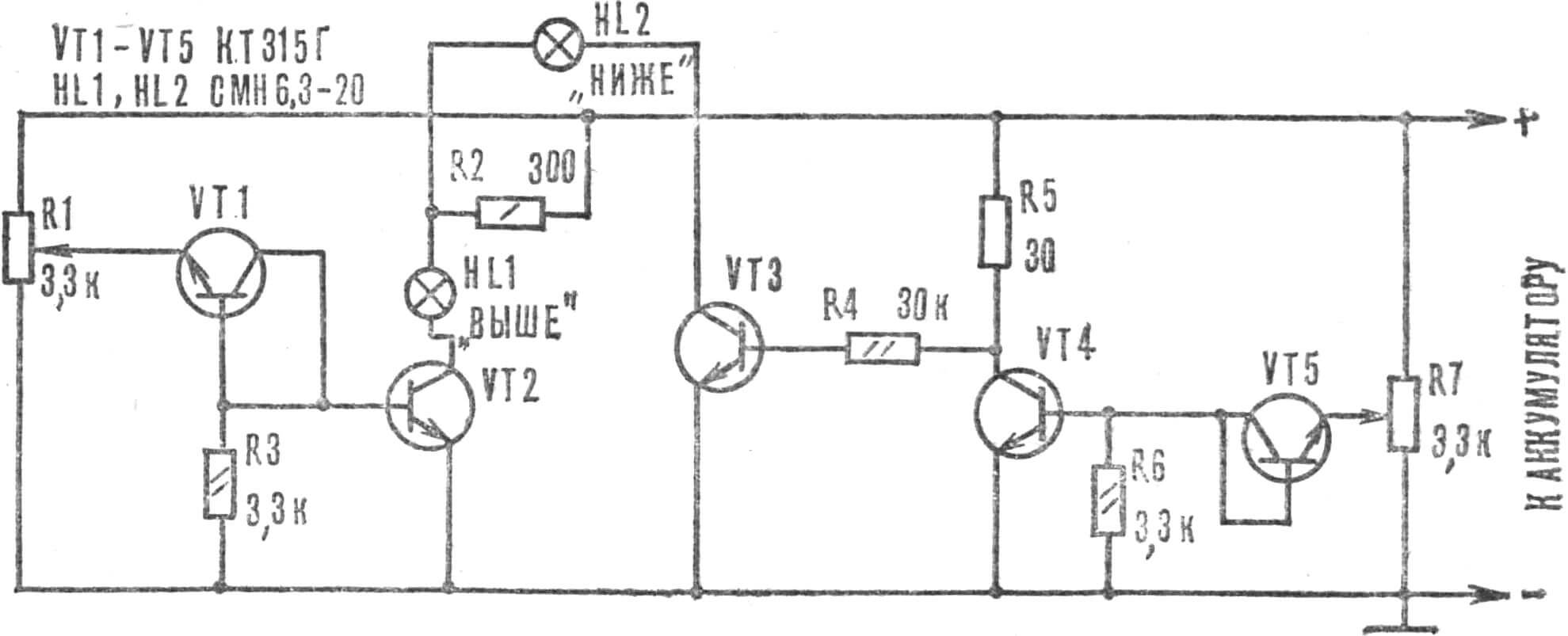
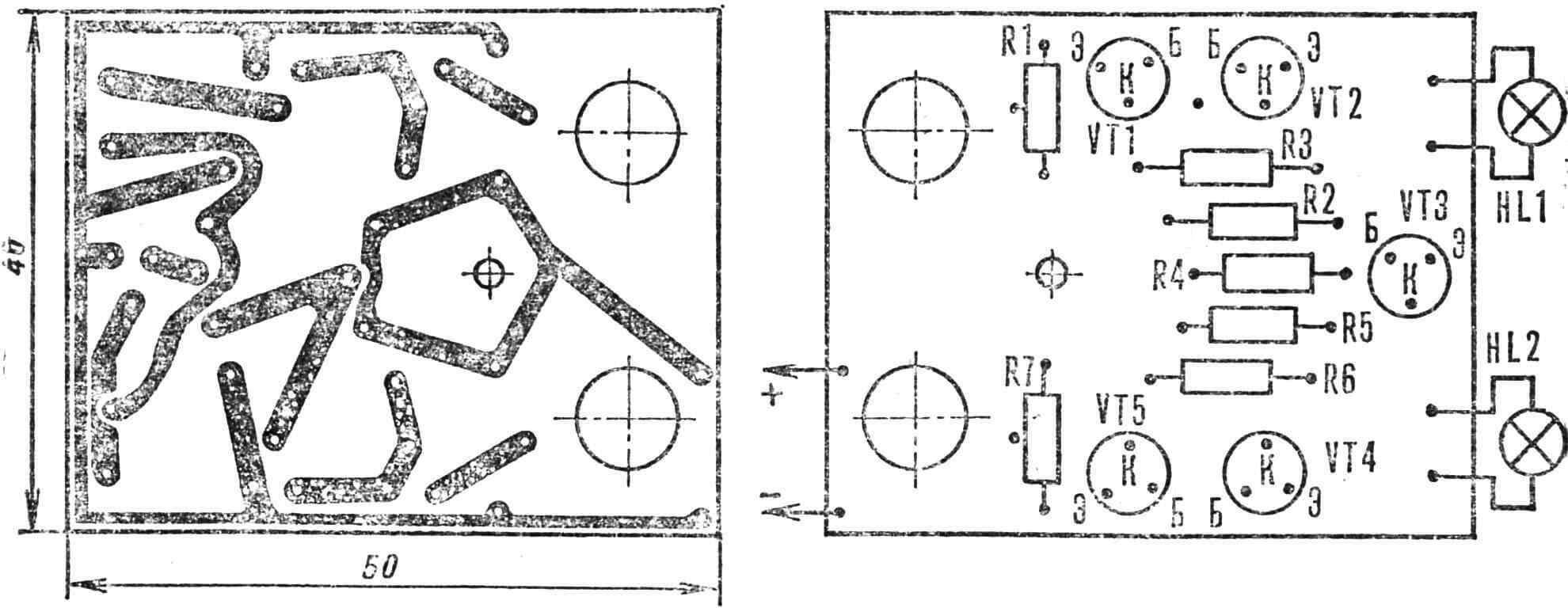
Figure 4 shows a schematic diagram of an autovoltmeter made entirely of transistors. It operates in the same way as IC-based autovoltmeters.
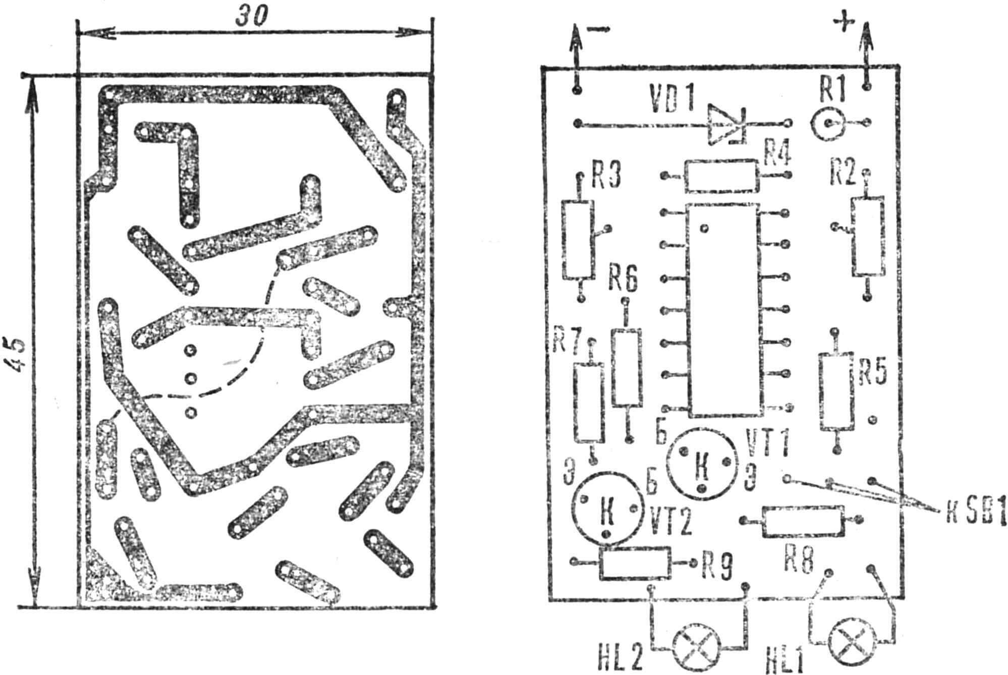
All devices are assembled by printing on boards (Fig. 5-8) made of foil getinax or fiberglass 1.5 mm thick.
The devices use fixed resistors – MLT-0.25, R2, R3 SP-16. Instead of the K155LAZ and K155LA4 microcircuits, you can install the K133 series IC. In addition to the KS147A zener diode, it is permissible to use KS156A. Transistors KT315G are interchangeable with KT315, KT312, KT601, KT605 with any letter index.
Instead of SMN6.3-20 lamps, you can install SMN9.0-60, but you will have to select resistors R8, R9 so that the maximum current does not exceed 60 mA.
An autovoltmeter for a motorcycle can be made according to the first two schemes (see Figures 1 and 2), however in this case it will be necessary to change the ratings of the following elements: R1 reduced to 39-43 Ohms (for KS147A) or to 30-36 Ohms (for KS156A), R2, R3 yes 2.2-6.8 kOhm, R8, R9 (see Figure 1) excluded, and in the diagram (Fig. 2): R8 390-430 Ohm, R9 560-620 0m, making sure that the current through the open LED does not exceed 10 mA for AL 102A and 29 mA for AL307A-G, with a voltage drop of 2 V on AL307A, B and 2.8 V for the rest.
To increase thermal stability, we recommend using two zener diodes of the same type, connecting them back to back.
In the third version of the autovoltmeter (see Figure 3), the values of the elements are not critical and can fluctuate within 20-30%, with the exception of R1, R8 and R9.
Instead of indicator lamps (see Figures 1, 3, 4), you can use LEDs by selecting resistors of appropriate values for them.
Setting up devices comes down to selecting the threshold voltage of the lower and upper limits. The engines of trimming resistors R2 and R3 are set to the lowest position according to the diagram. The assembled device is connected to an adjustable direct current source of at least 0.2 A and a voltage of 0-18 V. For the automotive version, set the voltage to 11.5 V and rotate the R3 engine until the lamp (LED) HL1 goes out. Then we increase the voltage of the power supply to 15.5 V and use resistor R2 to set the position at which the lamp (LED) HL2 lights up.
Check the adjustment performed in the following way: reduce the voltage of the power source to half the rated value, and then gradually increase it – first the lamp (LED) HL1 should light up slowly, at a voltage of 11.5 V it quickly goes out. Once the upper limit is reached, the lamp (LED) HL2 lights up. When the value is “Normal”, both lamps (LEDs) should not light up, and only when the SB1 button is pressed they flash.
To increase resistance to vibrations when used in a car, the board is coated with varnish or epoxy resin, placed in a polystyrene box and secured away from heat sources.
R. SKETERIS, Panevezys, Lithuania
Recommend to read
 TRIMARAN: SPEED AND MANEUVER
Racing sudomodel motor. Racing RC miniature electric scooters have always been popular with modelers, especially among those who only starts to master these amazing racing cars. This to...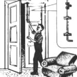 WHAT A CATCH!
In older homes, where there are very high ceilings and DEA-ri is much taller than a man, not everyone will be able to reach the top of the latch to open the door doctorcathy. Someone...
