
The journal has already reported on the advantages of rotary valve gas distribution in two-stroke internal combustion engines («M-K» No. 11 for 1974 and No. 10 for 1977). Here are their advantages in brief: achieving the highest specific power and fuel economy of the engine, improving starting and simplifying the cylinder design (no intake ports and pipes).
Currently, rotary valve gas distribution is used in the engines of many serial foreign road and sports motorcycles. It is also used on most serial outboard motors. In the USSR, disc valves are used by outboard motors «Vikhr», «Salyut», «Sputnik» (they have textolite valves), «Neptun» (capron) and «Privet-22» with a valve made of spring steel 1—1.2 mm thick.
«Privet-22» has the best fuel economy and specific weight among all domestic outboard motors currently produced. Based on this motor, by replacing water-cooled cylinders with air-cooled cylinders from the «Voskhod» motorcycle engine, it was possible to create a light two-cylinder in-line engine AG-2R with a maximum power of 30 hp. It can be built by any amateur designer with locksmith skills. The outboard motor «Privet-22» is available in many stores, and individual units and parts for it can be obtained by cash on delivery from the Kazan Motor Building Plant. Cylinders and cylinder heads of the «Voskhod» motorcycle engine can be easily purchased through Posyltorg bases.
From the outboard motor, the crankcase with crankshaft, starting, fuel and ignition systems are used — assembled with a flywheel magneto. A forced fuel supply device through a diaphragm fuel pump is also used.
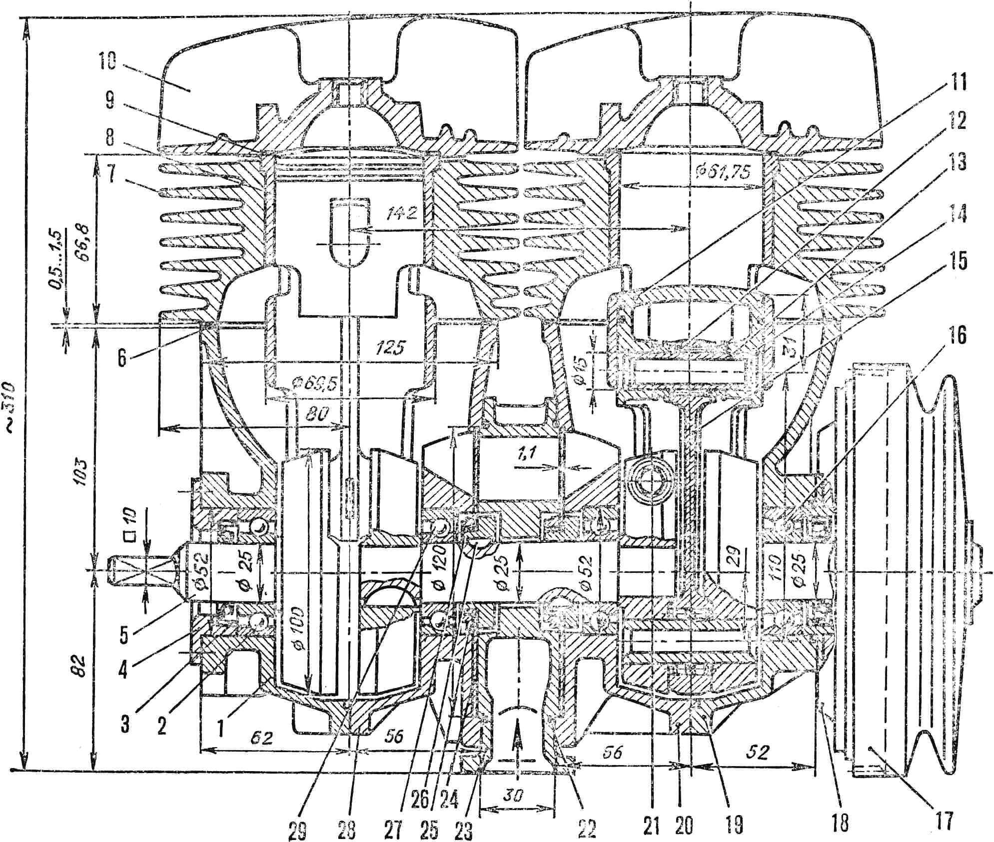
1, 19, 20, 23, 28 — crankcase parts, 2 — ball bearing No. 36205, 3 — seal, 4 — cup, 5 — crankshaft, 6 — set of gaskets, 7 — air-cooled cylinder, 8 — cylinder liner, 9 — asbestos gasket, 10 — cylinder head, 11 — piston with two rings, 12 — needle bearing of the connecting rod upper end, 13 — piston pin, 14 — retaining ring, 15 — connecting rod, 16 — ball bearing No. 205, 17 — magneto flywheel, 18 — magneto base, 21 — clamping bolt of split crankshaft parts, 22 — rubber sealing ring, 24 — rotary valve made of spring steel, 25 — valve mounting nut, 26 — segment key, 27 — valve bushing, 29 — middle ball bearing.
The longitudinal section of the engine is shown in Figure 1. The engine is a two-stroke air-cooled, two-cylinder in-line (cylinders are arranged in one horizontal row); displacement — 346 cm3; piston diameter and stroke are 61.75 mm and 58 mm respectively; maximum power 30 hp at 5800—6000 rpm; compression ratio (geometric) — 9.5; gasoline AI-93 or A-76 mixed with aviation oil MS-20 in a ratio of 1÷25.
The engine crankcase, taken completely from the «Privet» motor, consists of five parts cast from aluminum alloy. Their joint surfaces are vertical: two along the cylinder axis and two in the valve plane. Narrow sealing gaskets are placed between the parts. Each joint must be lubricated with sealant (BF-2 glue) before assembly. The crankcase parts are connected to each other with studs and M6 screws.
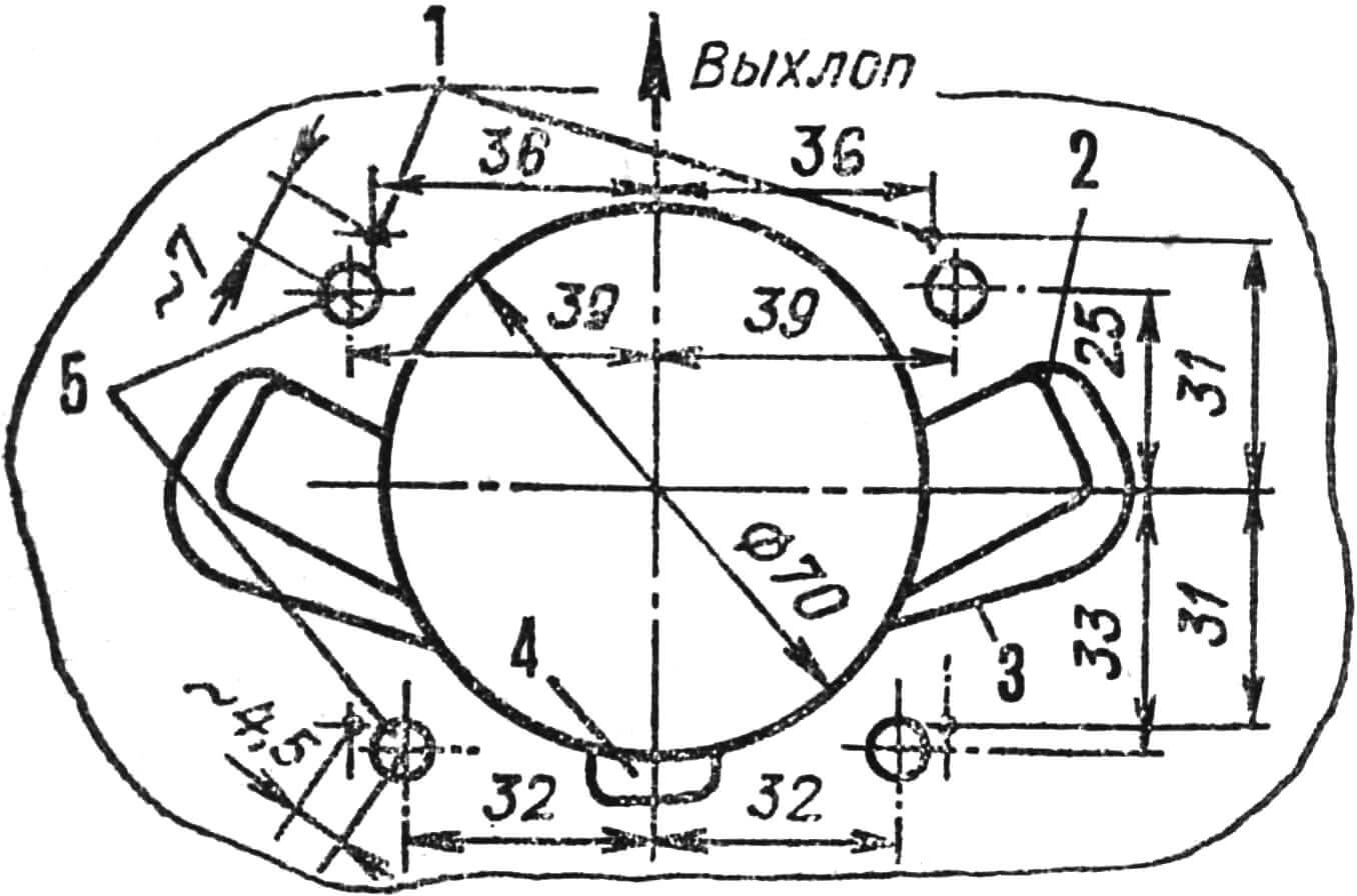
1 — axes of holes in the «Privet» crankcase, 2 — «Voskhod» scavenging channel contour, 3 — «Privet» scavenging channel contour, 4 — additional «Privet» scavenging channel, 5 — axes of holes in «Voskhod» cylinders.
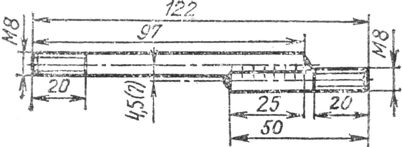
To install the cylinders, it is necessary to unscrew eight M8 cylinder mounting studs from the crankcase, plug the threaded holes with duralumin plugs 25 mm long with M8 thread, and drill new holes 25 mm deep for M8 thread (Fig. 2). Special studs welded from two rods offset relative to each other can be installed (Fig. 3). The engine crankshaft is completely borrowed from the «Privet» motor. The shaft consists of two cranks with a collet connection in the penultimate crank web on the flywheel side. The collet connection clamping bolt (see Fig. 1) is tightened with a force of 6±0.5 kg/cm. In the engine crankcase, a hole with a threaded plug is provided for its tightening with a special socket wrench. Four main supports of the crankshaft are equipped with widely used ball bearings No. 36205. The lower connecting rod ends are non-separable, mounted on double-row roller bearings with cages. The upper ends are on needle bearings also with cages.
Light pistons have two narrow chrome-plated steel rings 1.5 mm wide. This solution of the connecting rod-piston group of the motor ensures minimal friction in the units and significantly increases the reliability of the engine.
It is possible to install pistons from the «Voskhod» motorcycle on the connecting rods. But since their height is greater, it is necessary to place duralumin spacers 12 mm thick between the crankcase and cylinders. When selecting pistons and cylinders, the clearance between the piston skirt and cylinder should be 0.06… 0.08 mm.
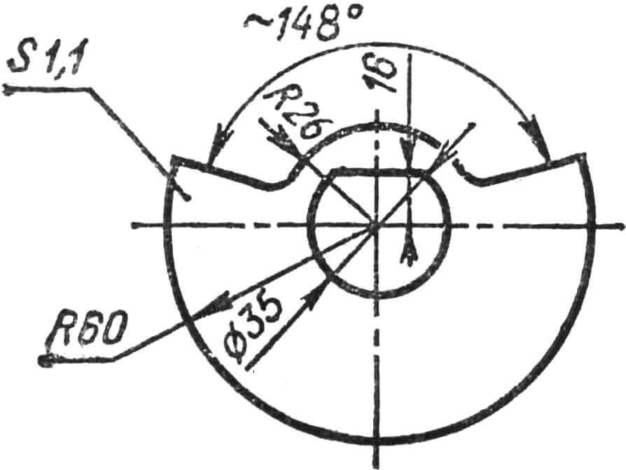
A distinctive feature of the engine is the use of disc valves Ø 120 mm made of spring steel 1.1 mm thick (Fig. 4) on the intake, which are placed in special cavities of the crankcase and freely slide along keys on the crankshaft. This is done for their optimal location in the slot cavities of the crankcase. The keys on the crankshaft are located 180° apart.
Mixture intake into the crankcase occurs along the shortest path — under the piston through the intake channel. Due to this, the resistance of the intake tract is significantly reduced and good sealing of the crankcase cavity during compression is ensured, since the valve cages have a free axial fit on the journal. When correctly installing the valves, it is necessary that the mounting nuts are to the left of the discs. To install two cylinders in a row with a center-to-center distance of 142 mm, the cooling fins of their heads are shortened on one side by 1 cm. In the area of the exhaust pipes, the bridges between the fins are cut through for through air cooling of the fins.
The cylinder liners are shortened from below by 4… 5 mm, and the cutouts at the bottom of the liners are expanded — cut — to 35 mm in width and 25… 27 mm in height to match the edges of the scavenging channels in the crankcase.
If special welded studs are used to mount the cylinders, oval holes 35 mm high are drilled in the lower fins of the cylinders for the passage of the thickened part of the studs.
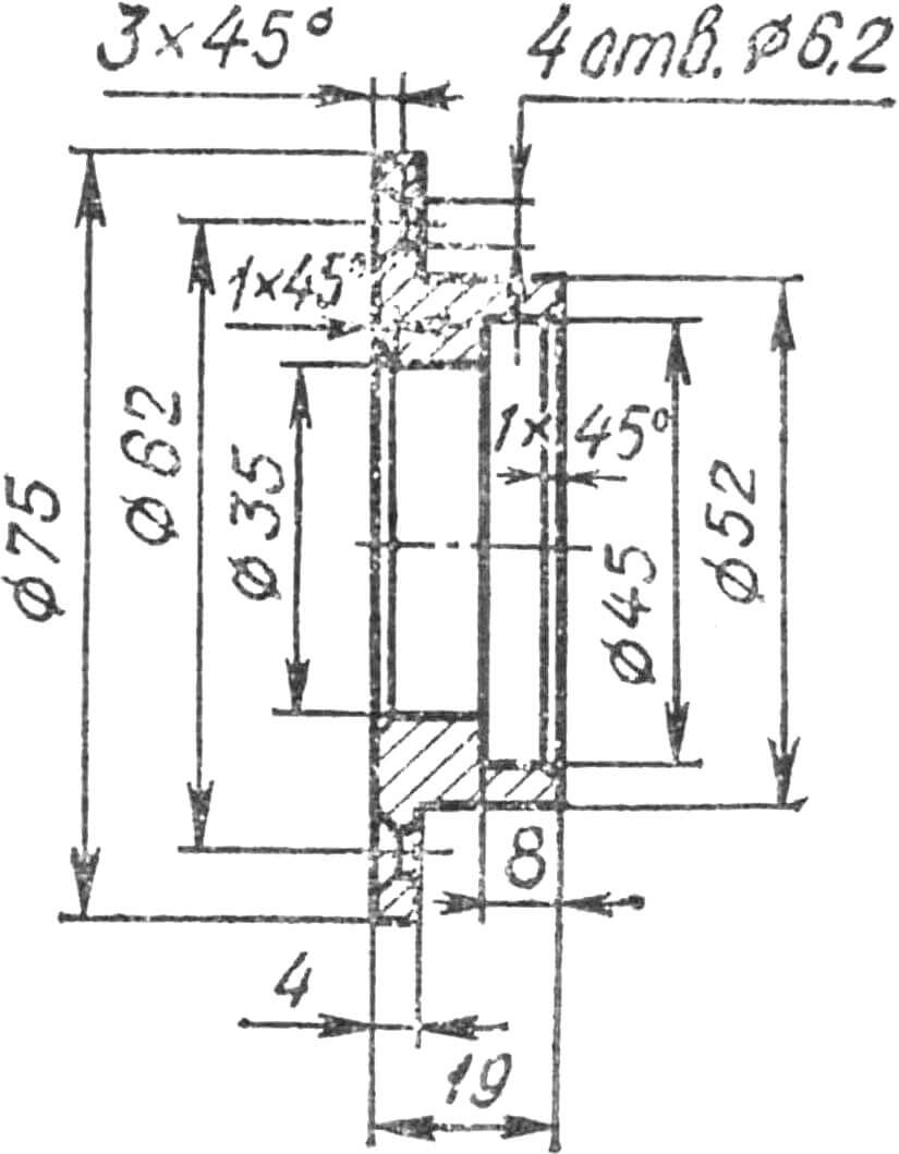
The required compression ratio in the combustion chamber is selected by a set of gaskets with a total thickness of up to 2 mm (between the cylinder and crankcase). Due to the fact that the crankshaft seal on the «Privet» outboard motor is located not in the crankcase, but on the motor mounting plate of the sternpost, a new duralumin cup (Fig. 5) is required to install a new seal directly in the crankcase of our engine at the crankshaft outlet. This is where any suitable seal for a Ø 25 mm shaft is pressed. The cup is attached to the mating plane of the crankcase with four countersunk M6 screws.
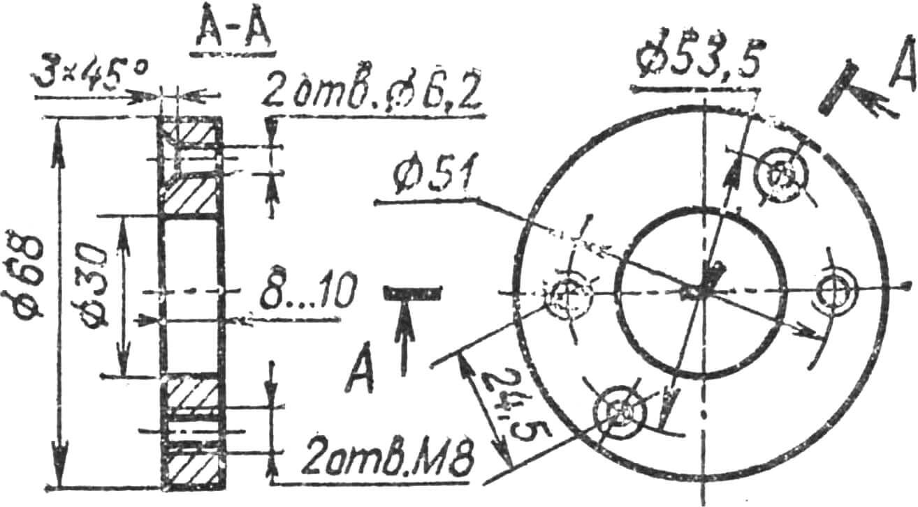
The carburetor of the AG-2R engine is from the «Privet» outboard motor or from the Izh motorcycle (carburetor type K-36 or K-62 with a central float chamber). In this case, the engine cylinders are arranged horizontally, and an adapter made of duralumin is installed between the crankcase intake port and the carburetor outlet pipe (Fig. 6).
A forced fuel supply system with a diaphragm pump can be used from the «Vikhr-M» outboard motor. The ignition and lighting system is completely from the «Privet» motor. These are: a two-spark flywheel magneto MN-1 with external high-voltage transformers TLM and SI12RT type spark plugs. The maximum ignition advance angle is 30° (2.5… 3 mm before top dead center). The magneto can be taken from the «Neptun-23» outboard motor, and the electronic ignition system — from the «Veterok-123» outboard motor.
The engine starting system, consisting of a gear ring on the flywheel, a starter with a starting gear, a pulley-shaft with a wound cord, is completely from the «Privet» motor.
The author hopes that the light two-cylinder medium-power engine AG-2R will interest designers of aerosleds, gliders, ekranoplans and hovercraft.
A. GERASHCHENKO, design engineer
Recommend to read
 ROLLING WARDROBE
Large sibelectroterm plants from time to time organize specialized exhibitions, where to study avenues its primary products are making their drawings. Among other things come across the...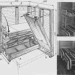 TECHNOLOGY ONE DESIGN DIFFERENT
Getting to self-designing furniture, I set a goal to achieve maximum adaptability to design was designed, manufactured, and operated with the lowest cost. I designed a set of furniture...
