Camber and toe-in of a passenger car’s wheels can be adjusted very accurately without going to a service station. You only need some basic metalworking skills and simple tools to make your own set of devices for this adjustment—simple and convenient to use. Consider as an example the VAZ 21063. The distance between the centres of the tyre tracks on the ground is 1365 mm. If you draw two parallel lines forward in the direction of travel through these points, they could serve as references for subsequent adjustments. However, this cannot be done on the car itself: the protruding parts of the side surfaces would get in the way. So these parallel lines must be drawn at some distance from the car. This can be done with a set of devices that can be called an angle gauge.
The basis of the angle gauge is a rail of hardwood or metal. Its sides must be strictly parallel. The rail length is 450 to 500 mm.
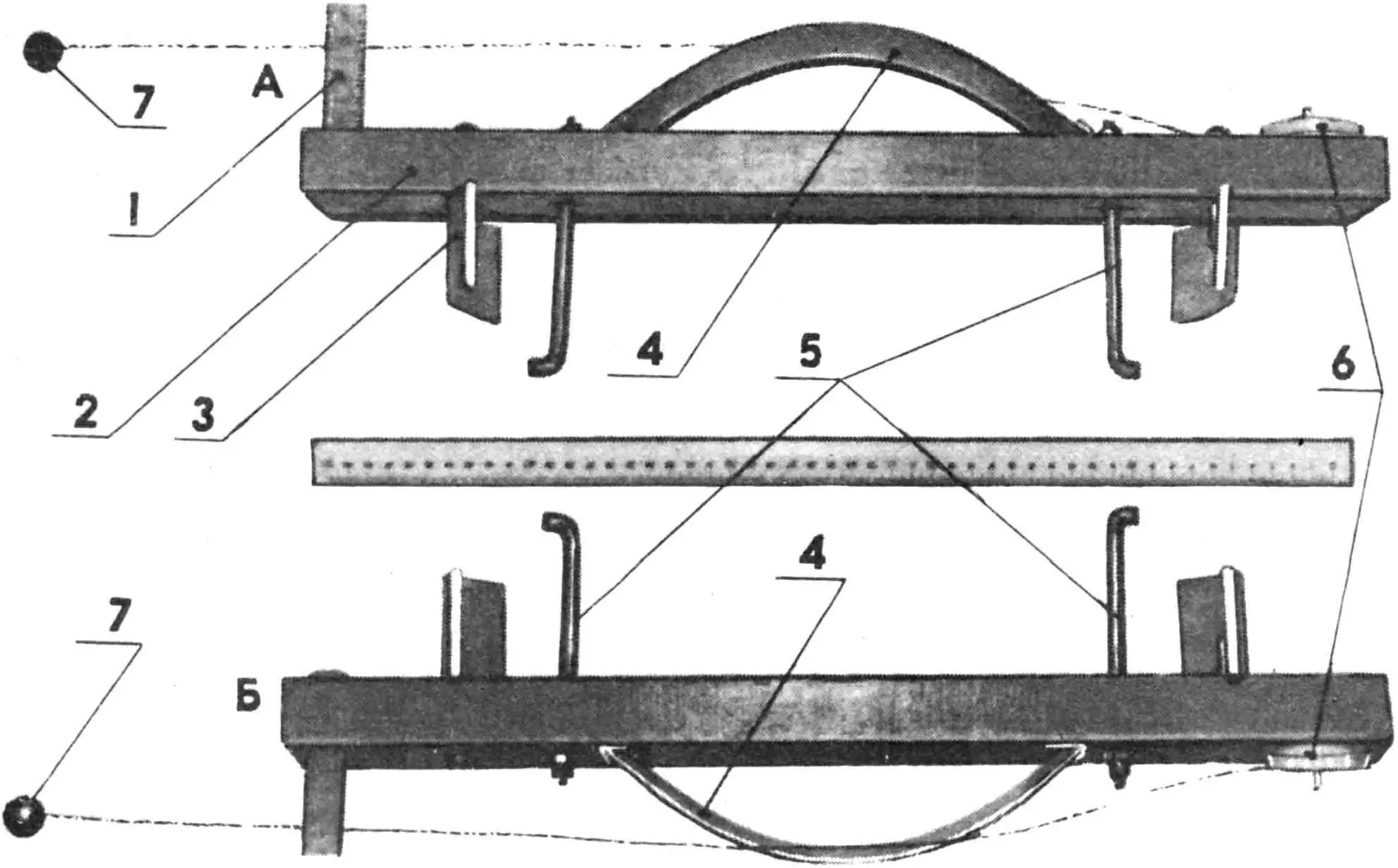
1 — millimetre ruler, 2 — base of the device (wooden block 30×70 mm cross-section), 3 — stops (2 pcs.; D16T; 4×50×120 mm), 4 — arc (D16T; strip 2…4 mm thick), 5 — studs with hooks (steel rod Ø 8 mm), 6 — spool with fishing line about 2 m long, 7 — plumb weight 20…30 g.
Photo 1 shows such a wooden rail 500 mm long, 30 mm thick and 70 mm wide. Photo 2 shows the angle gauge made from 25×25 mm square tube, 450 mm long. Two holes for Ø 6 mm studs are drilled at equal distance from the ends of the rail. The distance between their centres matches the wheel disc diameter — 360 mm. The stop studs are inserted into the holes. The stops are made from 4 mm sheet metal; length 120 mm and height 50 mm. The stops fit snugly around the disc edge, touching the tyre surface. The stop edge where it meets the tyre is cut at 45 degrees.
The gauge base is attached to the disc with special studs with hooks on the ends; tyre pressure should be normal. Using their flexibility, the base of the gauge can be aligned parallel to the disc plane. A ruler or callipers are used to check parallelism.
A spool with fishing line 0.2…0.3 mm thick, about two metres long with a 20…30 g plumb at the end is fixed to one end of the rail. A movable millimetre ruler 80…100 mm long is fixed with a screw at the other end. It is desirable that it can rotate about its axis—this makes measuring easier.
An arc of sheet metal 2…4 mm thick, 25 mm wide (photo 2) or 70 mm wide (photo 1) is mounted on the rail with its vertex strictly at the centre; it is secured to the rail with clamps or screws.
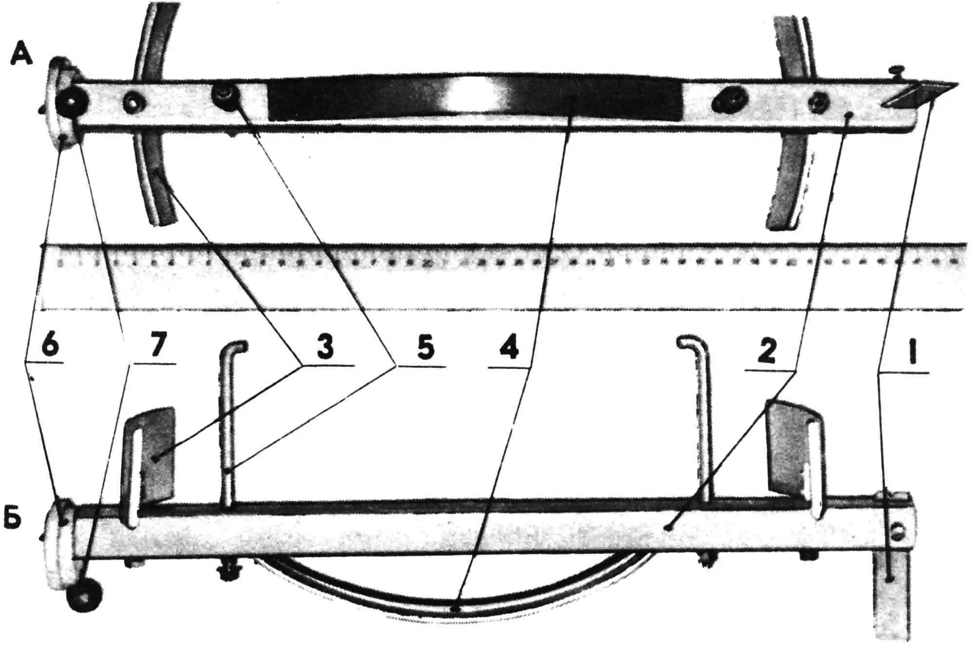
1 — millimetre ruler, 2 — base of the device (steel square tube 25×25 mm), 3 — stops, 4 — arc, 5 — studs with hooks, 6 — spool with line, 7 — plumb weight.
The reference mark on the movable scale (digit or mark) must be precisely aligned with the height of the arc. The line tensioned by the plumb along the arc surface and the scale mark is parallel to the rail plane, and the rail on the stops is in turn parallel to the wheel plane.
The set of angle gauges described here has identical parts and dimensions and the same adjustment procedure.
During wheel adjustment the car must be on a level surface. Access to the front lower part of the car must be provided.
Using a jack, raise the wheels in turn and fit the angle gauges perpendicular to the ground (scale down). The line or thread should almost touch the scale surface. Then lower the wheels under partial load. Following the adjustment recommendations (in the car’s owner’s manual), set the camber values.
When adjusting toe-in, the gauges are fixed in a horizontal position (or this is achieved by turning the raised wheel). The scale is aligned in the direction of travel. A rail, strip or board 1.5…1.6 m long is placed 1.5…2 m in front of the car at the level of the gauges. The lines with plumbs are pulled from the spools and, passing around the rail, form reference lines. Align one line with the scale of the left or right gauge. Set the second line strictly parallel to the first. You can then proceed with the adjustment according to the manual.
This angle gauge can be used for other cars too. You only need to allow for the wheel disc diameter and how the gauge is attached to it.
«M-K» 3’91, I. Drik
Recommend to read
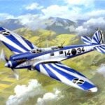 TESTED IN THE SKIES OF SPAIN
High-speed scout-bomber-70 BLITZ. One of the most famous planes created by the German firm Heinkel (Ernst Heinkel Flugzeugwerke GmbH) in the early 30-ies of the last century, became a...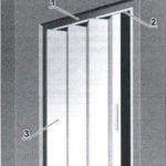 IT IS A PRACTICAL
Strict, rigid form of objects that surround us, evoke nostalgic memories of old times, when mass production did not exist, and each a "serial" product was manufactured individually,...
