At first, like most beginner radio amateurs, I drilled the mounting holes in printed circuit boards with a universal tool — an electric hand drill. However, it turned out that for making small holes (less than 3 mm in diameter) and with high accuracy, a hand drill is a poor assistant. After breaking quite a few bits and ruining several boards, I came to the conclusion that the process had to be changed and that I could not manage without a drill stand. When, after looking in shops and at markets, I failed to find one suitable for my old drill, I decided to make a small benchtop drilling machine. Fortunately, I already had some of the mechanisms and materials for it, first of all the electric motor and the chuck.
Before starting construction, I determined what kind of machine I needed. Two of the most common designs are known. In the first, the rotating tool is fed toward the workpiece fixed on the table. In the second, the table together with the workpiece is fed toward the cutting tool.
I decided to use the first option.
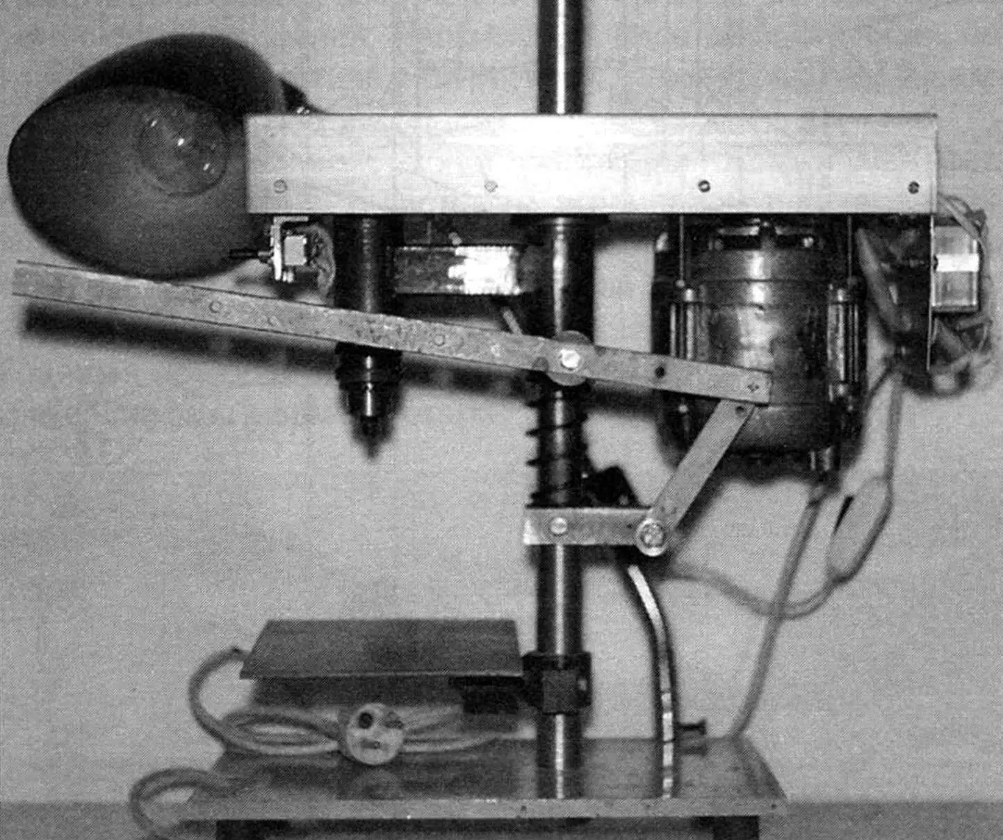
The design of the machine is quite simple, and its overall dimensions are relatively small: height × length × width — 410×315×250 mm. The last value is determined by the width of the base (it also serves as the work table), which is made from a 10‑mm thick duralumin plate. The base is “sprung” on rubber feet from some instruments, fixed at its corners from below. A column made of a steel rod 28 mm in diameter and 400 mm high is fixed to the base; all mechanisms are mounted on this column.
The mechanics of the machine can conventionally be divided into three main assemblies: the drive, the drilling head, and the feed mechanism that moves the tool toward the workpiece.
The drive is based on an electric motor from an outdated and therefore no longer needed washing machine “Tula”. The motor power is 180 W at 1370 rpm. It is mounted on one arm of a rocker — a steel plate 4 mm thick. By the way, the motor did not even require repair, only servicing — cleaning the commutator and removing graphite dust from the slightly worn brushes.
A driving pulley of the V‑belt transmission is fitted tightly on the motor shaft with a key. The driven pulley is mounted in the same way on the shaft of the drilling head located at the opposite end of the rocker. Torque is transmitted from pulley to pulley by a ring V‑belt of profile “0” and 750 mm long. The belt is of industrial manufacture, while the pulleys are home‑made, duralumin, two‑step. By turning over or rearranging the pulleys on the shafts of the motor and the drilling head, various spindle speeds of the cutting tool can be obtained.
The drilling head is the most critical assembly of the machine. When making it, it was necessary to ensure strict coaxiality of all parts in order to minimize tool run‑out and provide the required fits for the bearings. Since I had neither a lathe nor sufficient experience working on one, I ordered this assembly from specialists.
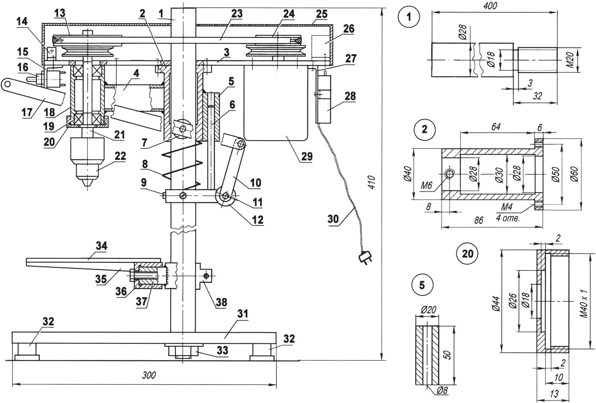
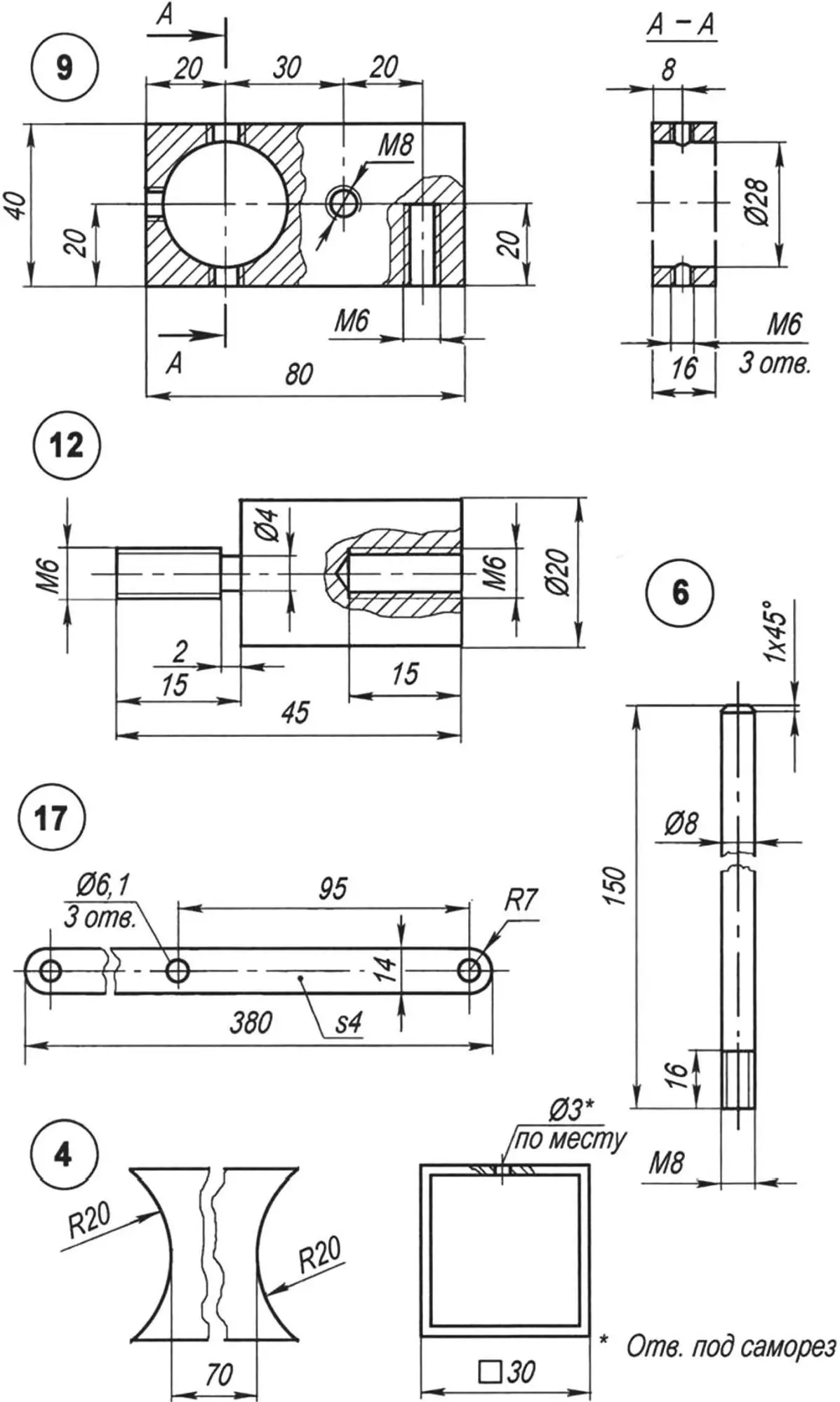
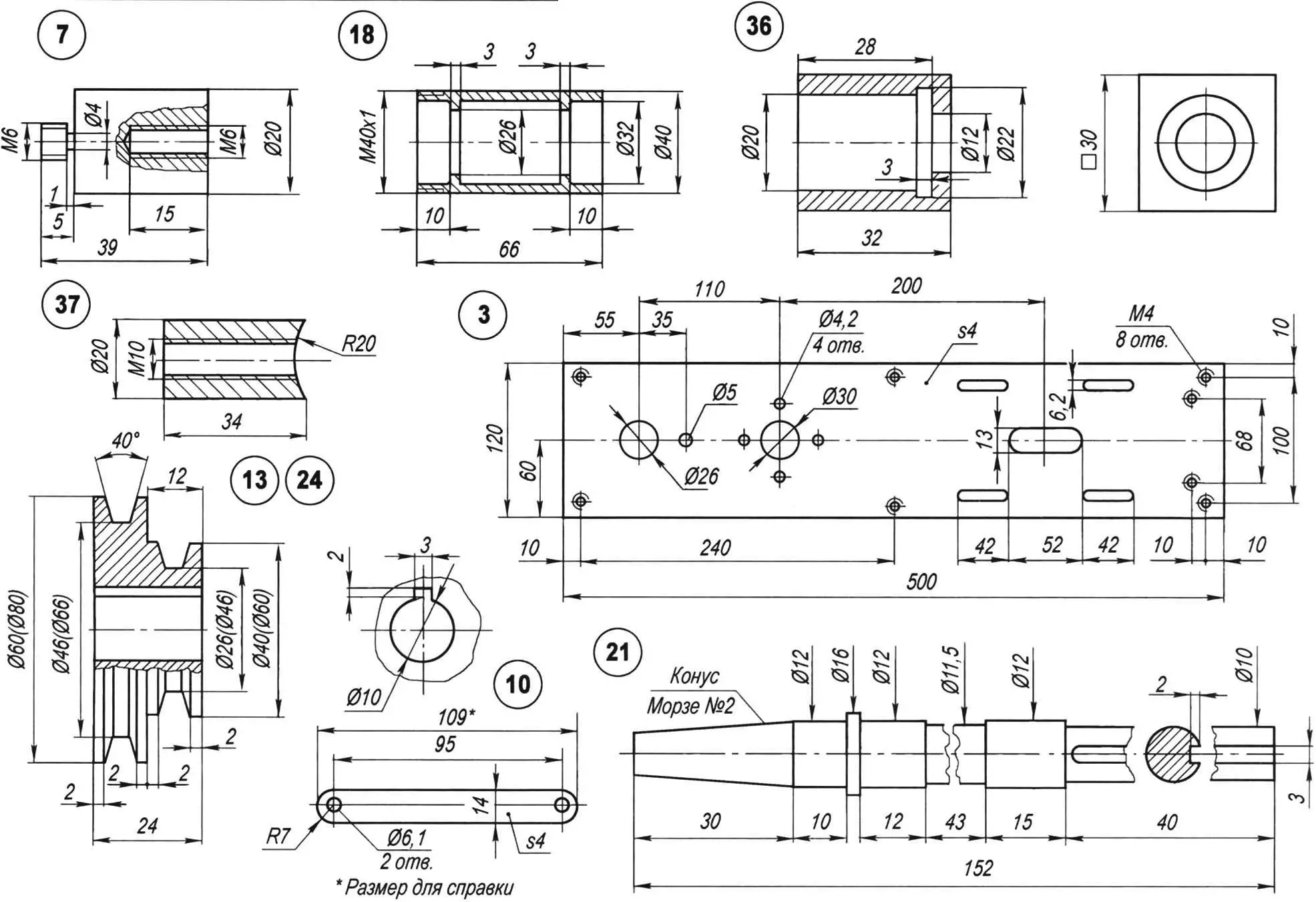
1 — main support column (steel, bar Ø28); 2 — main sleeve (steel, bar Ø60); 3 — rocker (steel plate s4); 4 — drilling head bracket (steel square tube 30×30); 5 — guide bushing (steel, bar Ø20); 6 — guide pin (steel, bar Ø8); 7 — handle spacer (steel, bar Ø20); 8 — normally extended spring; 9 — clamp (steel plate s16); 10 — link (steel strip 14×4); 11 — hinge pin (M6 screw, 3 pcs.); 12 — link spacer (steel, bar Ø20); 13 — driven pulley (duralumin D16, bar Ø80); 14 — drive‑guard bracket (duralumin angle 15×15, 6 pcs.); 15 — toggle‑switch bracket (duralumin angle 30×20); 16 — P2T toggle switch; 17 — lever‑handle (steel strip 14×4); 18 — bearing housing (steel, bar Ø40); 19 — bearing 201 (2 pcs.); 20 — bearing‑housing cover (steel, bar Ø44); 21 — spindle (steel 45, bar Ø16); 22 — chuck No. 2; 23 — V‑belt (type 0, L = 750); 24 — driving pulley (duralumin D16, bar Ø80); 25 — drive guard (duralumin, sheet s2); 26 — RT‑10 thermal relay; 27 — capacitor mounting plate (steel, sheet s2); 28 — capacitor 8 μF × 400 V; 29 — electric motor N = 180 W, n = 1370 rpm (from Tula washing machine); 30 — mains cable; 31 — base (duralumin, sheet s10); 32 — feet (rubber, from instruments, 4 pcs.); 33 — M20 nut (with washer) fixing the column to the base; 34 — movable table (steel, sheet s4); 35 — gusset (steel, sheet s4); 36 — swivel sleeve (steel, square 30); 37 — axle (steel, bar Ø20); 38 — terminal clamp with M6 screw
The spindle in the drilling head is mounted in two 201 bearings. The tool holder is a commercially manufactured chuck with taper No. 2.
The drive is mounted on the rocker, and the rocker in its middle part is attached by four M4 screws to the main sleeve fitted on the column rod.
For safety reasons, the V‑belt drive is covered from above with a guard made from 2‑mm duralumin sheet.
The drilling head is only joined to the rocker; more precisely, it is pulled to it by a long self‑tapping screw through a bracket that connects the bearing housing of the head with the main sleeve. The housing, bracket and sleeve themselves are rigidly connected by welding.
The sleeve can move freely (but without excessive play) downward — under pressure on the lever handle — and upward — under the action of the spring.
The “fulcrum” of the feed mechanism is the clamp, which is first slipped onto the column and then fixed on it by three M6 locking screws. Depending on the size (height) of the workpiece being machined, this “fulcrum” can be moved higher or lower along the column.
The possibility of turning this “fulcrum” on the column (and with it the drilling head) through an angle of up to 90°, and of placing the machine at the edge of a table, makes it possible to drill holes in long, narrow parts (slightly higher than the table) and even at the edges of wide ones.
For greater convenience when machining small parts clamped in a vise or even in pliers, an additional small work table was made. It can rotate both about its own axis and around the main column. The first option allows holes to be drilled in parts at an angle to their surface. This table, like the clamp, is fixed on the main column, but not with screws — with a terminal clamp.
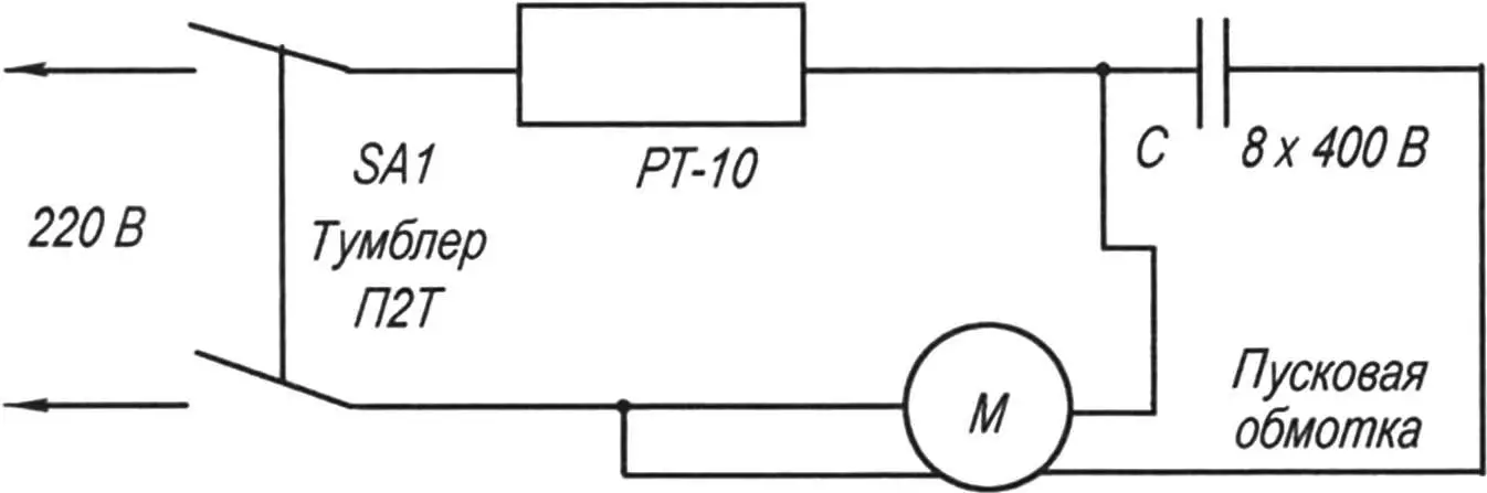
The thermal relay that protects the motor from overloads, and the capacitors that provide starting and normal operation of the motor, are also taken from the obsolete Tula washing machine. The wires and switches came from discarded household appliances.
«Modelist‑Konstruktor» No. 8’2008, Yu. Kurbakov
A motorcycle and a car are different machines. First and foremost, in terms of comfort. But can the advantages of two-wheeled transport be combined with the convenience of a passenger car? It turns out they can. Such two-wheeled machines—autorollers or motocars—are sometimes seen on the streets. We suggest you build one of these designs yourself.
This vehicle is a scooter with an engine of about 50 cm³ displacement, which, unlike traditional two-wheelers, has a light plastic body with a folding top, a seat almost like in a car, and two additional small wheels that can be raised and lowered like landing gear on an aircraft.
Let’s get to work. We’ll start with the frame. Obviously, you can’t build it without a welding set. You’ll need steel tubes with an outside diameter of 34 mm and wall thickness of 2.5 mm, tubes 22 mm in diameter (same wall thickness), and a front telescopic fork from any moped or scooter. The frame is designed for wheels from a Riga-built mini-moped, but scooter wheels will work too. You’ll also need sheet steel about 2.5 mm thick.
First, draw the frame full size. This will let you cut the blanks correctly and accurately from the drawing and finally fix the main dimensions of the parts.
As the drawings show, the autoroller frame is backbone-type and consists of a welded two-tube L-shaped spine that also acts as the rear wheel fork. To each tube, 4 mm thick steel plates with longitudinal slots for the axle are welded. We recommend cutting the slots after the plates are fitted—this helps get the work more accurate.
Now join the rear wheel to the frame tubes, tighten the axle nuts firmly, and mark where the bends will be. For a small bend you don’t need to pack the tube with sand—a tube bender is enough. After fitting, the tubes are welded at two or three points.
Next, fit the wheel in the front fork and fix the fork to the floor with wooden battens in the position shown. In the same way, set the frame spine with the rear wheel. Temporarily secure the spine to the steering column with soft copper wire. Check the wheel alignment carefully—they must lie in one plane. If correct, tack the spine to the steering column in two or three places. After final fitting, weld all joints fully. At the front, the spine-to-column joint is reinforced with gussets cut from 2.5 mm steel sheet.
The rear engine mounting bracket is cut and bent from 3 mm sheet steel. Do this in place: first cut a cardboard template and only after fitting make the metal blank. Fit the front bracket the same way.
After machining, attach the bracket to the engine and fix it on the frame with wire. Alignment must be checked again—the cylinder axis must lie in the frame’s plane of symmetry, and the carburetor platform must be level. After tacking the brackets, do a final check and complete the welding with the engine removed.
The frame base is ready. Add the cross tube that serves as the pivot for the extra wheels and small pads for the driver’s seat. The frame is then fully assembled.
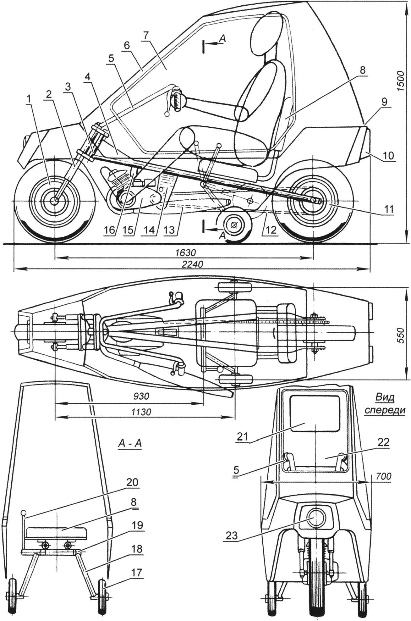
1 – front wheel (from mini-moped or scooter); 2 – front wheel fork (from any moped); 3 – frame steering column; 4 – reinforcing gusset from 2.5 mm steel sheet; 5 – handlebar (from mini-moped); 6 – folding glazed cab – “canopy”; 7 – block “glass” (Mylar film); 8 – driver’s seat (metal chair top, padded with foam and vinyl); 9 – hinge of folding cab (“canopy”); 10 – rear lights and stop lights (from motorcycle or scooter); 11 – rear wheel (from mini-moped or scooter); 12 – bushed roller chain (from two standard moped chains); 13 – muffler (from any moped); 14 – rear engine bracket (bent from 3 mm steel sheet); 15 – engine (Sh-58 or Sh-62 type); 16 – front engine bracket (bent from 3 mm steel strip); 17 – side support wheel; 18 – chassis strut (22 mm tube); 19 – support wheel pivot; 20 – chassis wheel raise/lower lever; 21 – rear window (Mylar film); 22 – front window (Mylar film); 23 – front headlight (from any moped)
For the extra wheels’ axle, choose a tube whose outside diameter allows it to rotate freely in the pivot. If you can’t find one, use a smaller tube or rod and compensate the gap with rings cut from plastic hose—they work well as plain bearings.
The chassis strut is made from 22 mm outside diameter steel tube. Weld a bushing to one end and a turned steel axle to the other. On the left strut, weld a short 10 mm steel rod with a thread for a plastic handle. This is the chassis control lever.
The extra wheels must lock reliably in both extended and retracted positions. The mechanism is straightforward; we suggest designing it yourself.
Chassis wheels can be from a children’s bicycle. Prefer rubber “balloon” or solid-rubber (not plastic) tires up to 200 mm in diameter.
The autoroller fuel tank is a 5 litre plastic or aluminium can. Fit a standard motorcycle fuel tap with sediment bowl and mount it at the rear of the body. Drill a vent hole in the can cap.
The body is plastic. The structure is built from 20×20 mm wooden battens.
The lower part of the body is like a small boat hull. Assemble the transverse frames from battens, then add the longitudinal battens per the drawing. Then skin the frame. Kitchen furniture plastic (sold in hardware stores) is a good option. Use epoxy for gluing the frame and skin. If you can’t find plastic, thin plywood or hardboard up to 3 mm is acceptable, or other options.
The upper part is built similarly. Glazing is transparent film of the kind used for model aircraft. Make window frames from 10×20 mm battens with spacers. Place the frame on the film, cut with a 20 mm margin, fold the film over and glue to the frame with BF-2 adhesive. Iron the joint with the iron set to “silk”. Then screw the frame into the window opening.
The window may not look perfect at first—Mylar is stiff and hard to tension. Use the iron set to “cotton” or “linen” and iron the film; it will tighten and flatten.
Final finishing is simple. With plastic skin, fill joints with epoxy filler (epoxy glue and talc) and paint with nitro primer then nitro enamel. With plywood or hardboard, level with filler, then cover with a layer of glass cloth and epoxy and paint.
Pay special attention to the controls. They are much like a moped’s. On the handlebar (from a Riga mini-moped) fit the throttle, front brake lever (right), and clutch lever (left). If the engine has a manual gear selector, mount it on the left of the handlebar.
The engine starter needs modification. At minimum, reposition the kickstarter lever on the splined shaft so it’s easy to kick from the seat. Better is a cord starter: fit a pulley on the splined shaft with two or three turns of nylon cord, run the free end to a convenient spot for a left-hand pull, and add a T-handle.
The last control is the chassis raise/lower lever—best under the driver’s left hand. The brake pedal for the rear wheel goes under the right foot.
For the first runs, leave the cab (“canopy”) off. Sit comfortably (chassis extended), put the gear in neutral, and start the engine. After warm-up, move off in first, then second. Retract the chassis only when the autoroller feels stable. Operating the extra wheels will feel odd at first but is easy to learn.
When using the autoroller, remember the engine runs cooler than on a moped. Ensure the cylinder cooling opening in the body is in the front wheel well, directly opposite the cylinder, and larger than the cylinder. If cooling is insufficient and the engine overheats, consider forced cooling. It’s not hard: remove the right crankcase cover and fix aluminium blades for a centrifugal fan on the flywheel/generator rotor. Make an air duct from bent aluminium sheet or from cloth and epoxy on a foam former, filled with plasticine or non-hardening putty.
«Modelist-Konstruktor» No. 6’2014, I. YEVSTRATOV, engineer
Recommend to read
 THE PCA MACHINE… CANS
Participants of military-Patriotic games from small to big deal for a clothing and "armed" with copies of famous machine guns PPSH, one form of which caused the enemy to panic:... “Boat”-snowmobile
I was born and raised in a region where the ground stays under a thick snow cover for most of the year — so it’s no surprise that people consider this place the homeland of Ded Moroz....
