This device helps detect hidden large metal objects at depths up to 0.6 m. It is needed by builders, gas service workers, and utility workers to search for metal manholes and covers that, during building construction or street reconstruction, ended up under a layer of earth, asphalt, or were covered by sand. With a metal detector, you can conduct various entertaining games outdoors and at home.
The device is powered by a “Krona” battery (9 V voltage), consuming 5—8 mA current.
The device’s operating principle is based on measuring the beats of two frequencies obtained from the reference and search generators. When the frame with the search generator coil approaches metal objects, its inductance changes, and along with it, the frequency of the search generator. As a result, the beat frequency also changes.
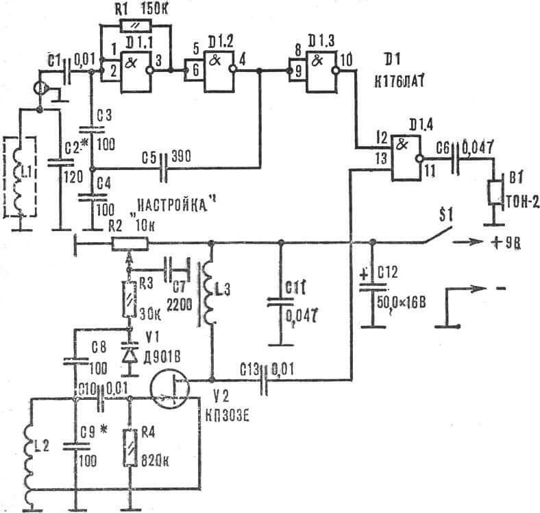
The search generator is assembled according to the so-called “capacitive three-point” circuit on elements D1.1, D1.2 of IC D1 (Fig. 1). Its frequency is determined by the parameters of the L1C2 circuit, which can be approximately calculated using the formula:
where L is inductance in henries, C is capacitance in farads.
A buffer stage is assembled on element D1.3, D1.4 serves as a mixer.
The reference generator is built according to an inductive three-point circuit on a field-effect transistor V2 of the KP303 series. Its frequency depends on the values of coil L2 and capacitor C9, as well as the capacitance of varicap VI. Coil L3 serves as the device’s load.
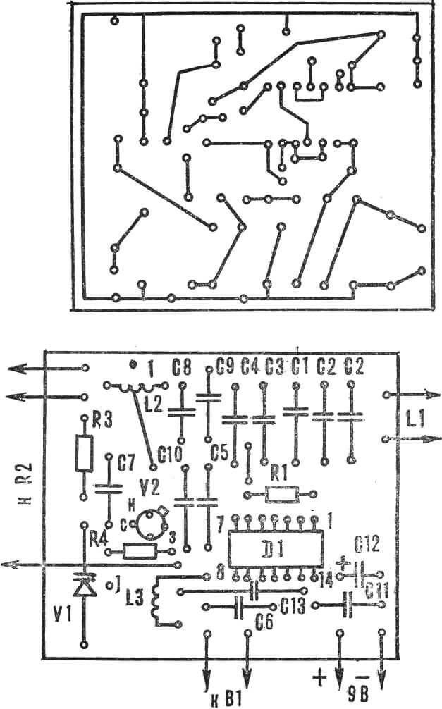
The device is mounted on a board made of single-sided foil-clad getinax or fiberglass 1.5 mm thick, size 65X55 mm (Fig. 2).
Coil L1 contains 100 turns of PEV-2 0.27 wire, wound on a ring Ø 250 mm, made from a vinyl plastic tube Ø 16 mm. The winding is wrapped with a layer of aluminum foil with a gap between the start and end of 4—6 mm to prevent a short-circuited turn. The foil is connected to the “negative” terminal of coil L1.
Coil L2 consists of 150 turns of PELSHO 0.14 wire, wound on a K8X6Х2 ring made of 1000НН grade ferrite. A tap is made from 1/3 of the turns, counting from the grounded terminal. Coil L3 is wound on the same ring until it is completely filled.
Resistors — MLT-0.25, VS-0.125 with a deviation of the value indicated on the diagram (Fig. 1) of ±20%. Capacitors C2—C5, C8, C9 — KM6-4b, C12 — K50-6, others — K10-7v.
Varicap V1 — any D901 series. Instead of transistor KP303E, a similar one with any other letter index can be used.
Setting up the device consists of checking the operability of both generators using a wavemeter or oscilloscope. By bringing the wavemeter coil closer, the presence of oscillations in the L1C2 circuit is determined and, if necessary, by selecting capacitance C2, it is tuned to a frequency of 100 kHz.
Using capacitor C9, the reference generator frequency is also tuned to 100 kHz at the middle position of resistor R2 slider. In headphones, a whistle produced by beats should be audible.
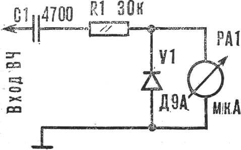
If there is no wavemeter, the device’s operation is judged by the signal shape on the oscilloscope screen connected to terminals 12 or 13 of D1.4. The presence of RF oscillations can also be verified using a simple probe (its circuit is in Figure 3). If the generators are working, then when connecting the probe to terminals 12 and 13 of D1.4 (Fig. 1), the indicator needle will deflect by some amount, depending on its sensitivity.
When tuning, instead of a fixed capacitor C2 or C9, it is recommended to temporarily install a variable one of any type. By selecting its capacitance value, they strive to obtain the loudest audio signal.
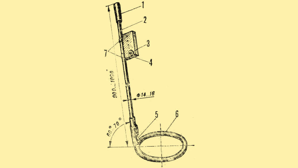
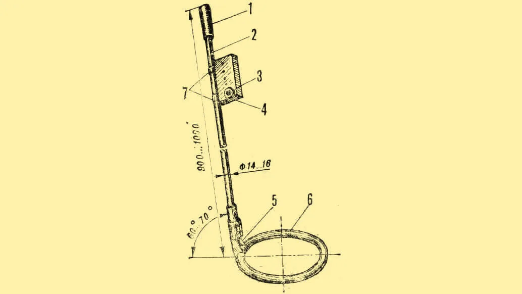
1 — handle, 2 — support arm, 3 — “tuning” regulator, 4 — housing with electronic unit, 5 — bracket, 6 — search ring with coil, 7 — housing mounting brackets.
The metal detector is shown in Figure 4. The arm with handle is made from a duralumin ski pole 900—1000 mm long. On it, at a distance of 80—100 mm from the handle, using two metal brackets, a housing with the electronic part of the device is secured. The search ring with coil is attached to the arm using a bracket at an angle of 60—70°. The wire connecting coil L1 to the electronic unit is laid inside the arm.
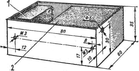
1 — “Krona” battery, 2 — mounting board (top wall conditionally removed).
The housing (Fig. 5) measuring 80X60X35 mm is made from 0.5 mm thick sheet metal. A hole Ø 5 mm is drilled in its side wall for installing the tuning regulator (R2). The mounting board is secured above it.
R. SKETERIS, Panevėžys, Lithuania
Recommend to read
 COAT OVEN
Older homes still sometimes there are amazingly cozy and beautiful tiled stoves. Alas, today, like the furnace heating, the tiles are fading. And they can be found only as a piece of... STRONG SCREWDRIVER
The old "stuck" or rusty screws and hard screws unscrewed in the usual screwdriver. But enough to drill in the handle hole and insert the metal shaft so the knob will be able to remove...
