Why “multi-welding”? Because this welding transformer (WT) has many important additional functions. Whereas in a traditional welder whose core is assembled from E- and I-shaped laminations there is often no room to squeeze in even one or two auxiliary turns, in the proposed donut-shaped design there is more than enough free space. As a result, it can weld with a 5 mm electrode on AC or DC, charge batteries, melt metal, supply safe voltage to woodburning tools in DIY clubs, and perform many other tasks. One could even pose the question differently: what other winding and for what purposes would the user of such a WT like to have additionally?
Indeed, the core of this welder, which has the shape of a “bagel” — a torus in mathematics and engineering — has a great future. Understanding this, but lacking special factory-made toroidal cores intended specifically for transformers, home constructors are forced to adapt cylindrical substitutes from the stators of old electric motors rated at 1–1.5 kW. To do this, the motor housings are usually simply broken apart, the windings laid in the slots are discarded as unnecessary, and the pole projections are cut off. And all this only in order to wind a mass of copper onto the resulting blanks (which look more like heavy, skewed, bottomless barrels than bagels) to achieve the “super goal” of welding steel with a 5 mm electrode!
I am convinced that electric motors should not be ruined, even if they have failed: a careful owner can always rewind burnt-out windings and replace worn bearings. A restored motor can still do a lot…
For the toroidal core I propose, 5–6 kg of transformer steel scrap is sufficient. Moreover, as a starting material you can even get by with the same amount of annealed roofing iron.
The technology for making a core from such material is fairly simple (Fig. 1). All flat transformer steel scrap is cut with shears into strips of approximately equal width.
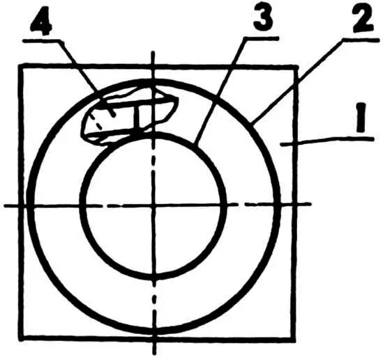
1 — base of the mold; 2 — outer cylindrical form (“ring gear” for the starter of a GAZ-53 truck); 3 — inner cylindrical form (a 60 mm long piece of 100×6 steel pipe, slightly turned and wrapped with two or three layers of paper); 4 — starting mass (plates 60–70 mm wide cut from scrap E- and I-shaped transformer laminations, coated with fast-drying glue such as office glue, gum arabic, or oil paint and laid with overlap, with cavities later packed with roofing offcuts)
In practice, you most often deal with rectangles 60–70 mm wide or slightly smaller pieces cut from E- and I-shaped laminations. All “transformer steel” and roofing offcuts are used. After being coated on both sides with some fast-drying glue such as office “liquid glass”, gum arabic, or even cheap oil paint, they are tightly stacked with slight overlap into a form (as when casting a hollow concrete column) made from improvised materials.
In the author’s process, the inner cylindrical form (Fig. 1) is a 60 mm piece of 100×6 steel pipe. Its inner surface must be turned slightly conical and wrapped (to make later removal from the “cast” core easier) with two or three layers of paper strip. As the outer form, a removable gear ring (inner diameter about 250 mm) from the starter drive of a GAZ-53 truck is used.
Of course, you may use other suitable blanks as forms, provided they can withstand the mechanical stresses arising during “casting” of the toroidal core. And those stresses are significant, especially when you have to hammer small plates into all gap openings (it is desirable that they match the stack width).
Once the glue has dried, the toroidal core can be considered practically finished. It still needs one-sidedly rounded half-rings — “half-bagels” — made of insulating material. Plywood will do, as it improves the laying of the future windings and prevents shorts on the sharp edges of the core. The same goal is served by prewrapping the torus with two or three layers of twill tape, fiberglass cloth, or fabric strip impregnated with linseed oil.
Now to the welder windings. Theory states, and practice clearly confirms, that a transformer operates in its most efficient mode when a current of 5 A flows through each 1 mm2 of the copper conductor’s cross section. Under extreme conditions, this value can be increased to 13 A, but then the conductors heat intensely and burn out.
To weld even with a 3 mm electrode, a current of at least 80 A is required. Accordingly, the cross section of the copper cable cores or the welding (power) busbar must match this. With a generous margin, it is usually in the range of 25–35 mm2 for a good home-built welding transformer.
Starting from the already mentioned “minimum welding” 80 A and taking into account the widely used ratio of turns between primary (mains) and secondary (welding) windings of about 5:1, we find that the mains winding current must be at least 16 A. It follows that the mains winding should be wound with copper wire of at least 3.2 mm2 cross section. However, perhaps the best option is enamelled copper wire (PEV-2) 2–2.5 mm in diameter.
It is commonly accepted (and confirmed in practice) that, for a “cast” core with a transformer steel cross-sectional area of 40 cm2, each turn of any winding corresponds to about 1 V. Considering possible mains voltage instability, the primary winding should be made with a safety margin. A good guideline is 250 turns. After the 190th turn, it is advisable to provide taps every ten turns (without cutting the wire). Naturally, the switch for these taps must be reliable and offer good electrical contact in order to avoid large energy losses and overheating during operation of the WT.
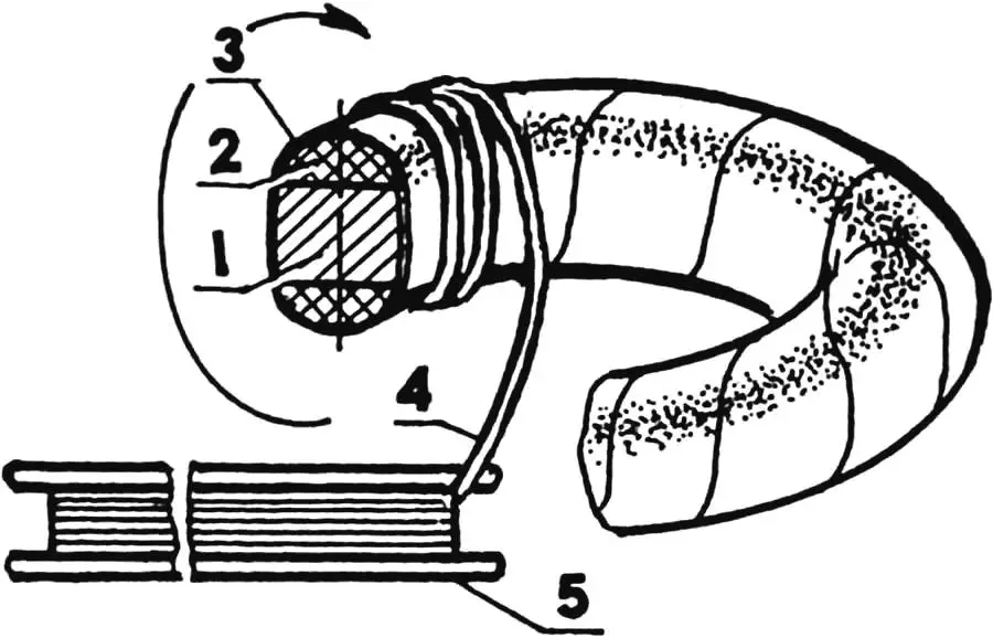
1 — toroidal core; 2 — one-sidedly rounded half-ring “half-bagel” of insulating material (2 pcs.); 3 — fastening insulating pad (2–3 layers of twill tape, fiberglass cloth, or fabric strip impregnated with linseed oil); 4 — mains winding wire (PEV-2, Ø2–2.5); 5 — wooden shuttle
Winding the mains coil is actually a rather difficult operation. It has to be carried out with long wooden shuttles (Fig. 2). Everything must be done carefully, avoiding crossing of turns, knots, and damage to the insulation lacquer layer on the wire. Otherwise, interturn shorts and overheating of the transformer are likely.
If the core is placed on two supports with a soft covering (padding) that prevents damage to the wire insulation while winding the WT, the whole job will take about two hours. It is desirable to complete it “in one pass” so that the winding does not loosen and remains as tight as possible, with insulating spacers between the layers.
After the mains winding is completed, it is advisable to test it at no-load. If, even after prolonged operation, the core with winding becomes only slightly warm, everything is in order. Significant heating indicates either too few turns or the presence of an interturn short (or even a breakdown of the winding to the core!).
On top of the two or three insulating layers over the primary, the secondary — welding or power — winding is laid. This is 40–80 turns of copper busbar or multi-core cable. The latter is preferable for several reasons: it can immediately serve as welding leads; winding becomes much easier; the service life of the welding winding increases while operating conditions are simplified — which is especially important when experimenting with such a WT. In addition, connecting a rectifier becomes easier, and it is possible to efficiently regulate welding current and voltage by a simple operation — winding or unwinding cable turns.
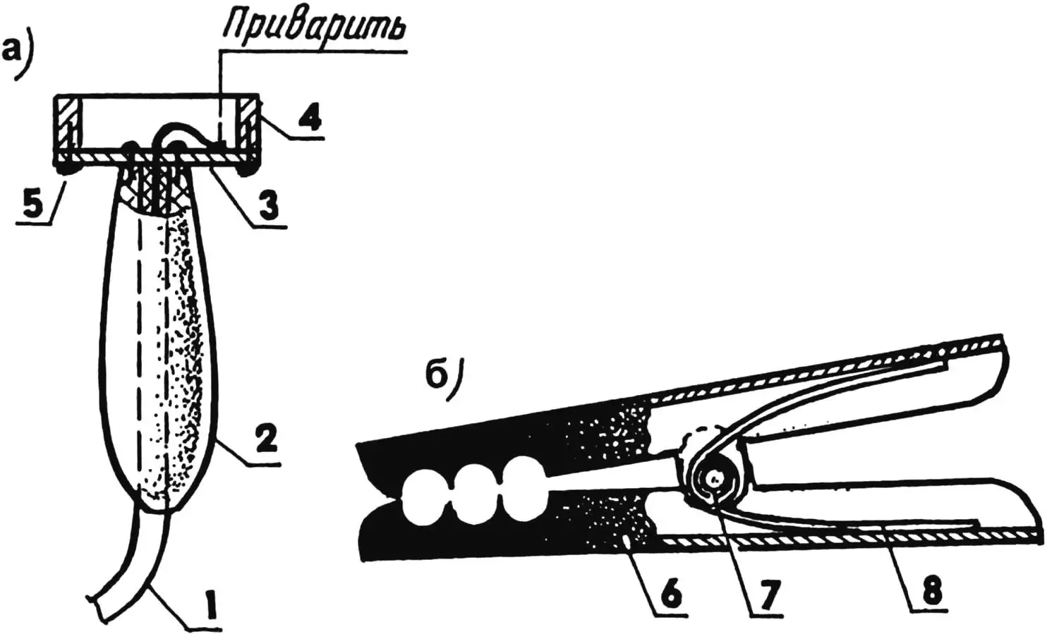
1 — welding cable; 2 — handle; 3 — steel plate; 4 — ring magnet “sticker”; 5 — screw (number and location according to installation); 6 — half of a home-made “toothed jaw” clamp (from a piece of steel pipe of suitable size, 2 pcs.); 7 — steel pin riveted at both ends; 8 — spring
For home-made, not-too-powerful welding sets, the following duty cycle is recommended: one minute of welding, two minutes of technological pause for cooling the WT. Small fans work well for additional cooling. Even better results can likely be achieved by using simple heat-dissipating radiators and mineral oils, which also improve insulation of the WT windings.
A good welding transformer should have a steeply falling external characteristic. This can be achieved by dividing the winding into two equal parts. On one side of the core, half of the primary and half of the secondary winding are wound; on the other side, the remaining halves are wound (and to avoid confusion later, in the same order).
It is worth recalling that a transformer is a reversible device: if any of its windings is supplied with the AC voltage it is designed for, the others will produce the corresponding voltages U~ for which they were intended. Many radio amateurs use this principle when identifying windings of an unknown transformer.
In view of this, it is by no means mandatory to wind the mains (primary) coil first and the welding (secondary) coil over it. The order of winding and numbering is mainly a matter of convenience for orientation in the schematic diagram of the welder. Therefore, if one of the windings must be wound with a rather stiff busbar that will require a mallet to lay, it is, of course, more convenient to place such “copper” first on the core so as not to damage the more flexible and delicate wires of the other windings.
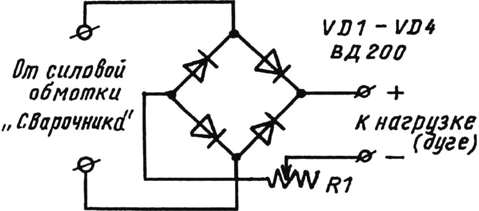
One more point. If you have plenty of wire for one winding and very little for another, start with the one where your possibilities are limited. When cable or busbar is clearly insufficient for the secondary (welding) winding but you have powerful diodes — semiconductor rectifiers — it becomes advantageous to give up AC welding in favor of DC (Fig. 4). In this case, the WT output voltage and, accordingly, the number of turns of the welding winding can be kept minimal. If the busbar has damaged insulation, it is recommended to anneal it first with water quenching (the copper will become soft), insulate it with shellac and fiberglass, and only then wind it onto the core.
Home constructors often have difficulty attaching the work lead to the part to be welded: either the contact is poor, or there is nothing convenient to clamp onto. Two simple devices (Fig. 3) can help — a magnetic work clamp and a crocodile-type clamp. Both designs are very simple to make and are quickly and conveniently attached. If contact is insufficient, it is enough to rub them slightly against the workpiece.
It is also useful to equip the primary winding of the WT with a standard AP circuit breaker rated at least 30 A. It provides convenient disconnection of the transformer during pauses between welds. This saves a noticeable amount of electricity, creates favorable conditions for timely cooling of the unit, and makes operation safer. And with a powerful rectifier (Fig. 4), the set can be used, as already mentioned, for charging batteries or for multi-station low-voltage supply of soldering irons and woodburners in school DIY clubs. Moreover, such a unit is truly indispensable for small-scale electroplating at home or for starting a car in cold weather.
Equipping the WT with an additional winding that consists of just a single turn of annealed copper busbar 5×50 mm or a thick multi-core copper cable about 20 mm in diameter (with lugs made from pieces of thick-walled copper tube) is very interesting and promising. Practice has shown that such a winding allows hot free forging, hardening and bluing, soldering and surfacing, bending of strip, pipe, thick steel bar and rod, brittle wire, casting of tin, zinc, and lead, loosening “seized” bolts, studs, and nuts, spot welding, shrink-fitting, and a number of other operations.
How can smooth current control be achieved? One way is the method already mentioned — by adjusting the number of turns of the power (cable) winding. When part of it is unwound from the core, the voltage decreases while the WT current increases, but arc ignition conditions worsen. Conversely, adding cable turns increases the transformed voltage while reducing the output current, and the arc ignites more easily.
Another option is to connect the welding cable to the work not directly but through several turns of high-resistance wire (nichrome, for example). The number of such resistive turns determines the number of steps in welding current regulation. In all these cases, arc ignition remains almost the same.
The WT current can also be controlled using a combined magnetic shunt made of transformer steel and non-magnetic metal. In this case, a transverse slot is made in the core.
Plumbers, motorists, repair technicians, and simply enthusiasts who like to make things with their own hands — this welder with such universal capabilities is for you.
“Modelist-Konstruktor” No. 2’2004, R. Kravtsov
Recommend to read
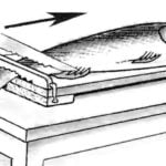 “TRAP”… FOR FISH
It is not intended for fishing and for retaining fish during cooking to cleaning her scales. Anyone had to do this knows how difficult it is to hold slippery fish. However, secure on the... THE RADIO WAVES
The easiest way to cast him "into the ground" — in sand-clay the form obtained by pressing it to the plane of symmetry of the model Bulba, carved out of wood. Bulbs obtained from...
