A built-in wardrobe is good already because it takes at least half as much material to make as a conventional carcass unit, yet it holds far more, since it is usually made full height from floor to ceiling.
A sliding-door wardrobe has doors that overlap and do not need the extra, often considerable, clearance required, for example, by swing doors — and the wider the doors, the more clearance they need.
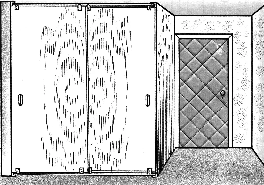
Both advantages are combined in the wardrobe I designed for the rather narrow hallway of my apartment.
Those whose hallway layout is similar to mine can use this sketch design if they wish and need to. But I think it may also be useful when fitting out other rooms.
The wardrobe structure is extremely simple. The frame (if it can be called that — it does not even have uprights) consists only of four corner cross-members. On the front ends of the cross-members, top and bottom, pairs of tracks for the rollers are mounted. The enclosing panels are two doors and only one side wall. The other side, as well as the floor, ceiling, and back of the wardrobe are the corresponding structural parts of the building.
The corner cross-members of the frame are made from 25x25x3 mm steel angle. Their length matches the pier of the partition wall that serves as the wardrobe side. Stepping back from the front edge by the door thickness (16 mm), M8 nuts are welded to the horizontal legs of each of the four cross-members to fasten the first track. The nut centre coincides with the setback line. Then, moving inward by a distance equal to the roller axle length plus a 3–5 mm gap, another such nut is welded for the next track. Between the nuts, and farther along the cross-members, three 5 mm holes are drilled in the horizontal legs of the angles at roughly equal spacing to fix the parts to the apartment floor and ceiling with construction steel anchors. M8 threaded holes are made in the vertical legs of two cross-members — with countersunk screws they attach the side panel.
But before installing the cross-members on site, you must check floor and ceiling level. If there are deviations, packers must be placed under the angles in the right places so that at least their front ends lie in one plane. This is needed to keep the upper and lower tracks horizontal (otherwise the doors may roll by themselves or even drop out of the upper tracks).
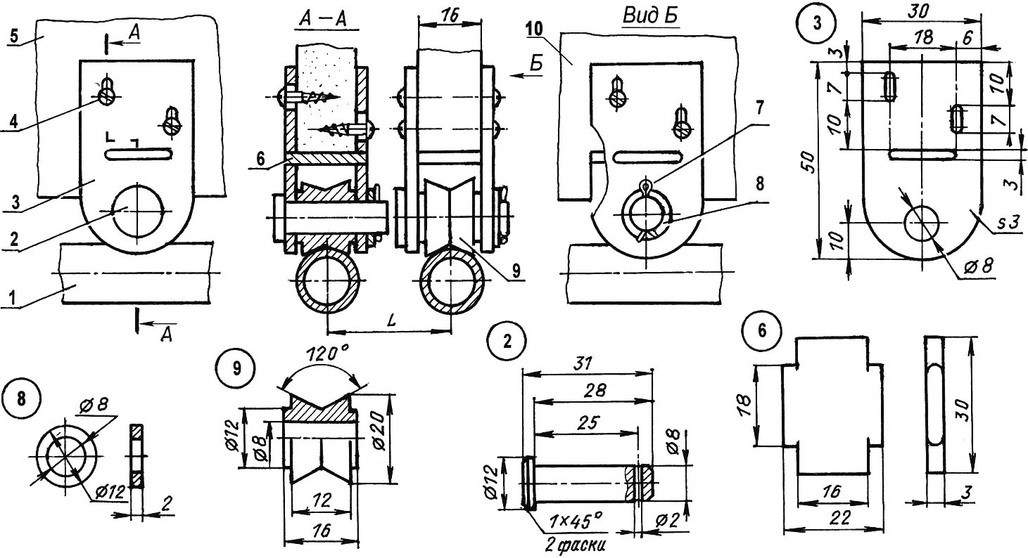
1 — track; 2 — axle (modified M8 steel bolt); 3 — cheek (3 mm steel sheet, 2 pcs.); 4 — 15×3 screw (4 pcs.); 5 — outer door leaf (chipboard); 6 — tie plate (3 mm steel sheet); 7 — Ø2 cotter pin; 8 — 12x8x2 washer; 9 — roller (steel, Ø20 round); 10 — inner door leaf
The tracks (four of them: two upper and two lower) are identical to each other. They are made from steel pipe with an outside diameter of 17 mm and wall thickness 2.8 mm. The pipe ends, over a length equal to the width of the inner part of the cross-member angle leg, are cut to a depth equal to the sum of the angle leg thickness and the nut height (but preferably 1 mm less). 8.5 mm holes are drilled at the ends of the tracks for bolts.
If the frame is assembled with a helper so you do not have to “chase” millimetres (which you should do for every operation), you can first join the tracks to the cross-members and then fix the latter to the floor and ceiling with anchors.
The roller mechanism is my own design; it can be made at home in a domestic workshop. It consists of a pair of identical cheeks with a tie between them and a roller with an axle. Besides these, two standard parts are used: a washer and a cotter pin. The axle is made from an ordinary long M8 bolt with the threaded portion cut off.
The cheeks are made from 3 mm steel plate. Each has an 8 mm hole for the axle and three slots: two vertical — for fixing screws and one horizontal — into which the tie shelf is inserted. The screw slots are offset from each other in a kind of staggered pattern. This prevents the screws from meeting when driven from outside and inside; you only need to be careful during assembly and set the opposite cheeks correctly. The screw slot length allows tilt adjustment of the doors (removing skew and gaps between their vertical edges and the side walls) by placing shims between the tie and the lower edge. The tie is made from the same plate as the cheeks.
The roller is made from a steel blank 16 mm thick like the door and 20 mm in diameter. I considered this diameter optimal.
To keep the roller from sliding off the round tubular track, I gave its rim a triangular groove. The profile could have been concave to the tube radius, but a roller with a triangular rim is more universal and suits any track diameter.
When developing the roller mechanism, I planned to weld the tie to the cheeks — that would simplify making the unit. But then the joint would be non-demountable, which could greatly complicate hanging the doors in the opening, since I wanted to mill recesses in the chipboard for the roller mechanisms to reduce the gap between the door horizontal edges and the tracks. In general, such grooves are not mandatory. You can hide the gaps with strips fixed to the lower and upper door edges.
The roller axle, as already said, is made from an M8 bolt: the shank is shortened to the required size, a transverse hole for the cotter pin is drilled at its end, the head height is halved, and the wrench flats are ground off. After assembling the mechanism, a washer is placed on the axle from the inner cheek side and secured with a cotter pin. The axle can also be made from a tube by flaring one end to form a shoulder and drilling the wall for a cotter pin on the other. Roller mechanisms should be mounted on the door no closer than 50 mm from its edges.
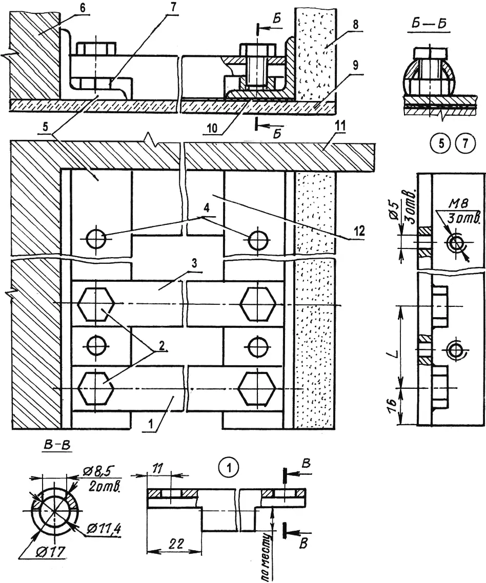
1,3 — outer and inner tracks (steel pipe 17×2.8); 2 — track fastening (M8 bolt, L12, 4 pcs.); 4 — cross-member fastening (construction anchor, 3 pcs. per cross-member); 5 — cross-member (25x25x3 steel angle, 2 pcs.); 6 — room partition; 7 — widened M8 nut (4 pcs.); 8 — wardrobe side panel (12 mm chipboard); 9 — floor (ceiling); 10 — shim; 11 — apartment wall; 12 — skirting board
(Threaded holes are drilled only in the two cross-members on the side-panel side)
My sliding wardrobe is two-door. The inner and outer doors are the same size, but when choosing their width remember that when closed (one fully left, the other fully right) they should overlap in the middle by 50–70 mm. In height the doors should leave at least a 5 mm gap top and bottom between their horizontal edges and the tracks. This is needed to ventilate the wardrobe interior, to adjust door skew, and for smooth travel. Both leaves are 16 mm chipboard — enough for room heights up to three metres. It is good if the chipboard sheets are flat; if they are bowed, install them so the bulges do not face each other — otherwise the leaves may rub. It is better not to fit handles — they get in the way of full opening. Instead, cut hand slots in the door panels at 1200–1300 mm height. The side wall is the same chipboard as the doors, but a thinner sheet can be used if you do not plan to load it with many shelves.
If the door panel width does not allow covering the opening with two leaves, make a three-door wardrobe by placing two doors on one track (outer or inner).
When the wardrobe is built against an external wall of the house, leave 20–30 mm gaps between the door horizontal edges and the tracks to improve ventilation inside the wardrobe. To make these less visible, cover them below with a threshold and above with a cornice running the full wardrobe length.
I do not describe the interior layout and finish of the sliding wardrobe here — everyone decides that individually according to their needs and taste.
“Modelist-Konstruktor” No. 8’2006, A. TIMOFEYEV
Recommend to read
 ON ONE BOARD WITH A SAIL
Of course, sailing the Board someone able to buy in the store. However, most can't afford it. Such will want to do it yourself. Especially since there is no design supercomplex forms. To... Il-76TD-90VD
Despite the high performance, engines and avionics of the Il-76 aircraft leave much to be desired. Excessive noise and emission of pollutants to the environment, made it impossible for...
