Washing machines have firmly become part of everyday life. And while connecting a modern washing machine to a water supply network in cities is usually easy, in rural areas with no centralized water supply, where water is taken from springs and wells, putting such a machine into operation is much harder. This is primarily caused by the absence of a water supply system or insufficient pressure in it. As a rule, modern washing machines are designed to work with inlet water pressure of 0.5 — 10 bar, which can only be provided by a booster pump or an autonomous pumping station based on it (the latter can now be bought starting at 153 US dollars).
Usually in villages, washing machines are connected by a familiar scheme: a barrel of 50 — 200 liters is installed above the washer, and water flows from it into the machine by gravity through hoses, valves, and adapters. But this pressure is clearly insufficient.
Water, passing through the built-in electromagnetic inlet valves of the washing machine (there are two), a filter, and a nipple, enters the tank so slowly (literally drop by drop) that you would have to wait days and nights for washing to start and end, which is essentially absurd.
In addition, the “smart” electronics of washing machines “do not understand” such treatment, interpreting slow water accumulation as a complete lack of water in the house, and as a result stop the wash cycle (this depends on brand, model, and machine type).
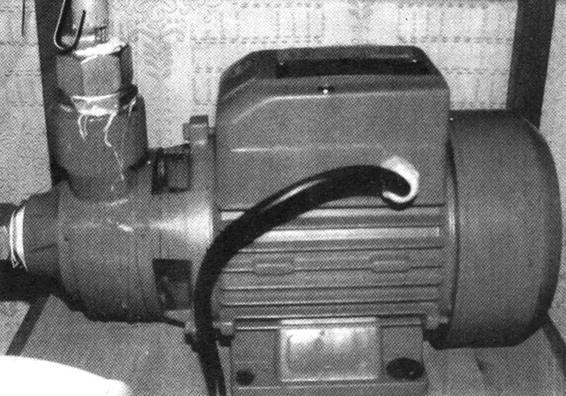
However, practical DIYers came up with a simple way out — connect a water-boosting pump in series with the washer’s standard inlet hose. Moreover, for this purpose you can use almost any pump type: submersible pressure, centrifugal, or vibration — depending on preference. Pump prices also vary: from 34 to 128 US dollars, but all of them will create the inlet-circuit water pressure required by the washing machine. A submersible or vibration pump must be lowered into water; a centrifugal pump draws water through a hose and delivers it through a hose as well.
DIY users connect the pump to 220 V mains through a regular household switch (for example, one used for lighting), assuming that when the machine “asks for water,” you press the switch — and water at the required pressure, sufficient for the washer, will enter the drum and tank.
But two questions arise. First: how do you know when it “asks for water”? You cannot switch on a pump (even a very reliable one) with a closed outlet — failure is inevitable. And the situation of a “blocked” outlet is exactly what a closed inlet valve of the washer imitates when the machine does not need water.
The second question is even more relevant: since a standard washing machine (in the price range up to 611 US dollars) “requests” water several times during washing and then, depending on the selected mode, at least twice for rinsing laundry (also filling water in portions), will the homeowner have to constantly “watch” the machine for hours to feed it water at the right moments?
Unfortunately, the answer is yes. According to villagers, many people without pumping stations (which replace a regular urban water supply) do exactly this.
Meanwhile, there is a simple and seemingly accessible solution for almost any rural resident or member of a country gardening association, which I am glad to share with readers.
Almost all washing machines (hereinafter WM), regardless of manufacturer and label, operate on the same principle: one or more solenoid valves are installed at the inlet and powered by 220 V AC mains through an electronic control and switching system.
Such professional terminology should not scare the reader, because modifying a washing machine in this part is, as they say, easier than easy.
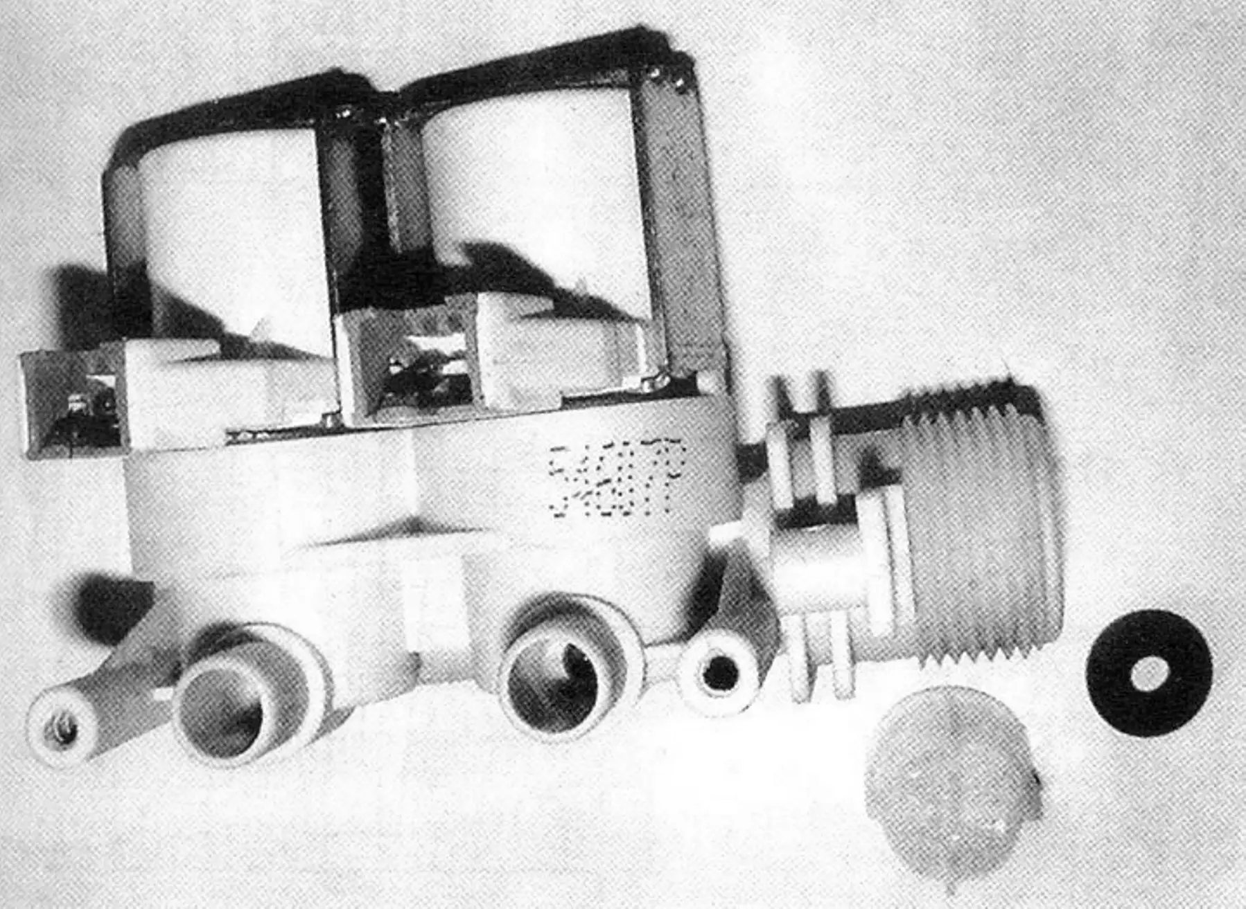
To ensure unobstructed water flow, remove the rubber gasket in the inlet connector opening of the washing machine (shown in photo 2). After that, valve throughput improves significantly.
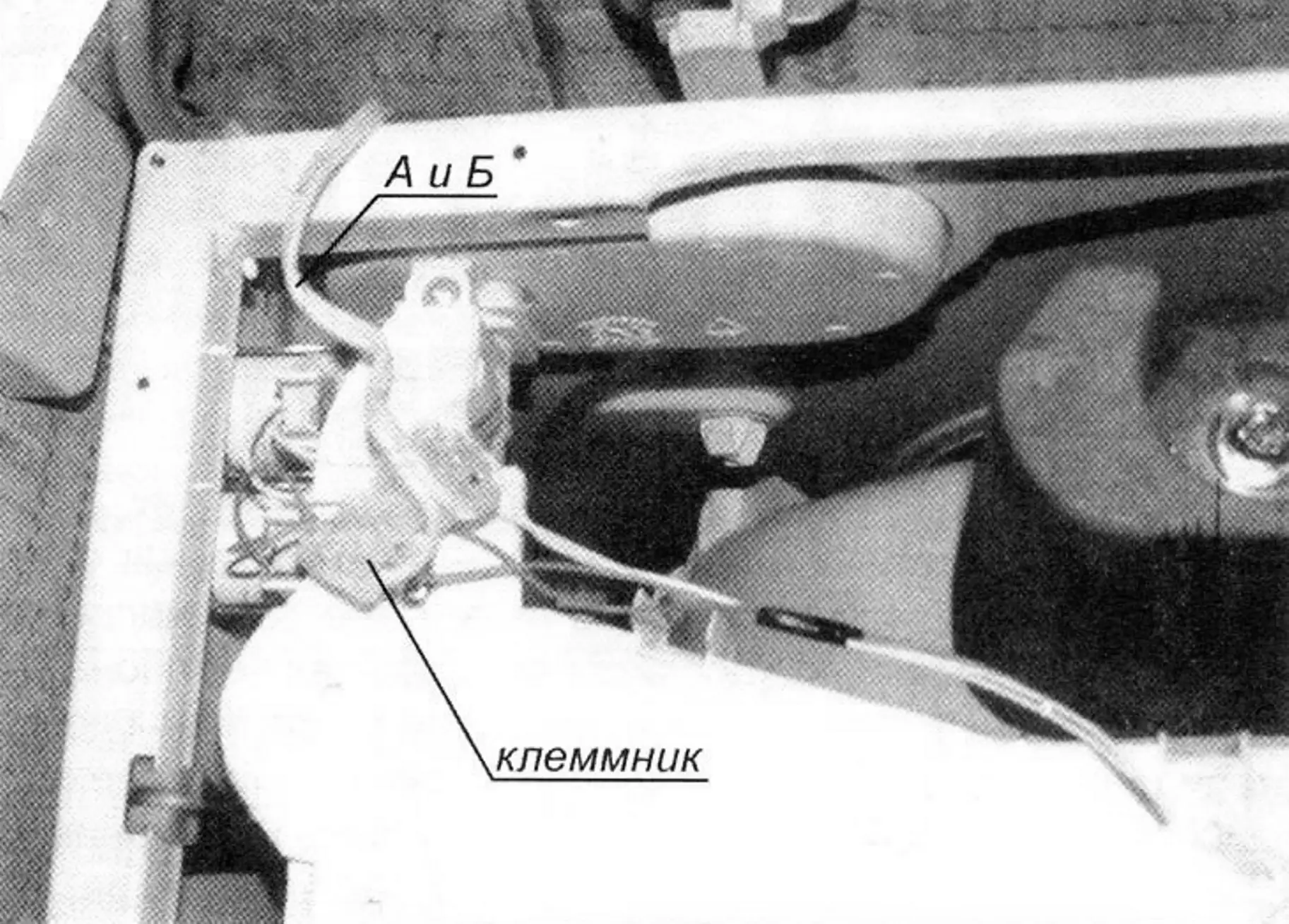
Next, remove the top cover of the washing machine (this refers to side-loading machines) by unscrewing two or three screws (depending on WM type) on the rear panel near it. The top cover is removed with a horizontal forward motion “away from you” (if facing the hatch door). Near the inlet hose connection point, two solenoid valves are located side by side (in the WM considered) (photo 2). Wires are connected to them via connectors. When water must be filled into the washer, 200 — 220 V AC is supplied to the inlet solenoid valves. They open and let water into the tank and drum. Four wires go to the solenoid valves (two per valve). By connecting a terminal block in parallel to the valve contacts (photo 3) and attaching a pair of wires, they are routed outside the washing machine housing.
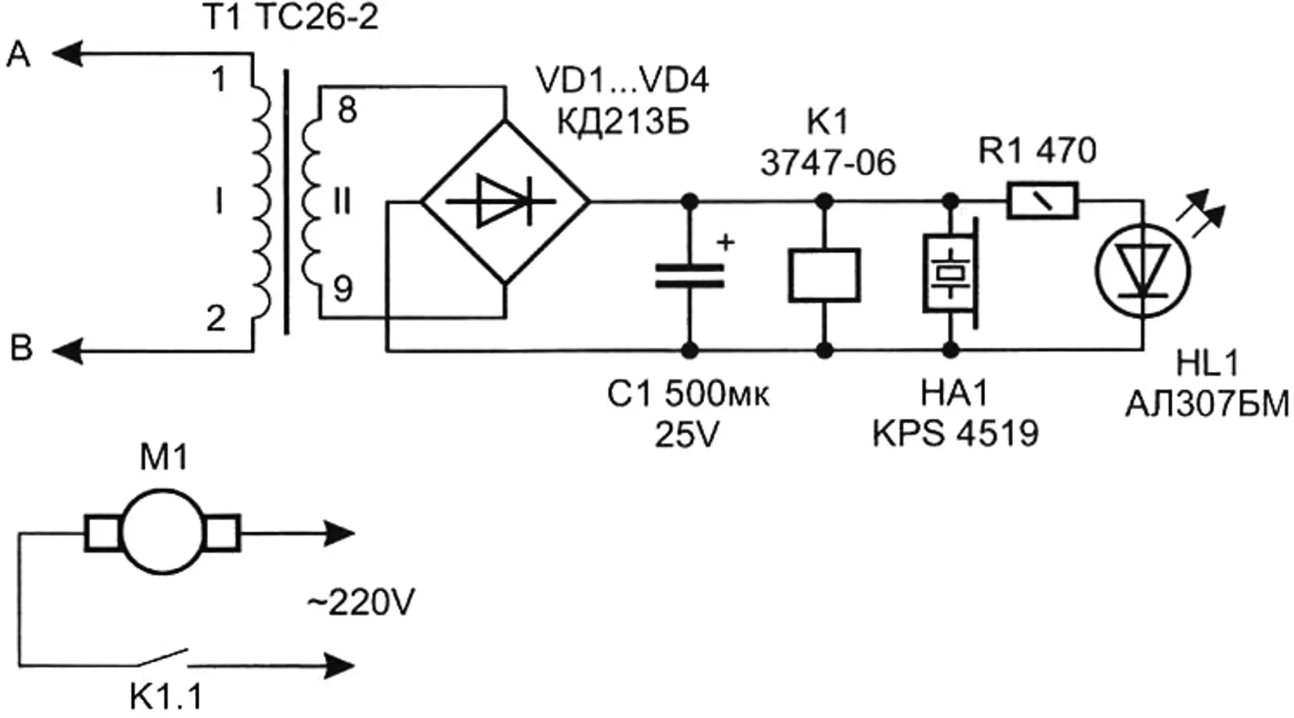
Now these wires (let us conventionally call them A and B) are connected to a simple electrical circuit (Fig. 1).
In essence, the device circuit is a rectifier (DC power source) with output voltage of 12 — 15 V. Any voltage in this range is acceptable.
At the output of the DC power source, a low-current electromagnetic relay K1 is installed. The contacts of this relay are inserted into the break of the pump power circuit. Now, as you have already guessed, when the inlet valves of the washing machine switch on, relay K1 and electric motor M1 of the booster pump switch on as well. When the washer valves switch off, the pump automatically turns off. Such a pair will work cyclically for as long as needed. There is no need to stand near the washing machine anymore.
You cannot connect the pump directly to the contacts of the washing machine’s solenoid valves — because the pump’s high current consumption will burn out the WM electronics.
About components
The diagram (Fig. 1) shows step-down transformer T1 with secondary winding AC output of 8 — 10 V, and a rectifier on diodes VD1 — VD4. Oxide capacitor C1 (type K50-24 or similar) is included to smooth power pulsations. Relay K1 is an automotive type 3747-06, rated for 12 V actuation. However, others can also be used, for example WJ118-1C, Omron G2R-112P-V, TRU-5VDC-SB-SL, TTI-TRD-9VDC-FB-CL, Relpol RM85-2011-35-1012, Pasi BV2091 SRUH-SH-112DM, FRS10C-03, or similar. It is important that relay contacts provide safe switching of load current not less than 3 A.
The diagram also shows piezo capsule HA1 with a built-in sound generator connected in parallel to the relay, and LED HL1 connected in series with current-limiting resistor R1. These elements provide, respectively, sound and light indication of pump activation (and washing machine inlet valves). If such indication (or part of it) seems unnecessary, the corresponding elements are simply removed from the circuit.
Capsule HA1 can be any unit rated for 9 — 15 V, for example FMQ2715D, FXP1205 (single-tone sound), KPI4332-12 (intermittent sound), KPS4518 (two-tone siren), or similar.
The rectifier shown in the diagram (Fig. 1) can be any one, as long as it provides output DC current above 70 mA at constant output voltage of 12 — 15 V. This can be an industrial rectifier or a power supply unit, for example for a radio receiver or woodburning tool. Mobile phone adapters are useless here, because output current is insufficient to power the relay.
In this simple way, you can automate operation of almost any automatic washing machine in a village and do laundry as in the city. And there is no need to look for an installer who will charge substantial money for the work.
Apparent drawbacks
You will need to open the top cover of the washing machine and connect in parallel to the solenoid valves by installing a terminal block. If the washing machine is under warranty, unauthorized opening of the cover may void it. Here everyone chooses for themselves: either struggle until the warranty expires, or buy a used washing machine and then modify it according to the recommendations above and wash clothes comfortably.
“Modelist-Konstruktor” No. 3’2010, A. KASHKAROV
Recommend to read
 Aero L-29 Delfin (Czech Republic)
The development of L-29 was started in 1955, took the initiative by a group of engineers from the Research and test flight Institute of Czechoslovakia. First flight of L-29 made the... PATTERNED FRAME
For those who do not have the skills in doing the carving, but wants to make a product decorated with a simple pattern, it may be advisable to start with the manufacture of the original...
