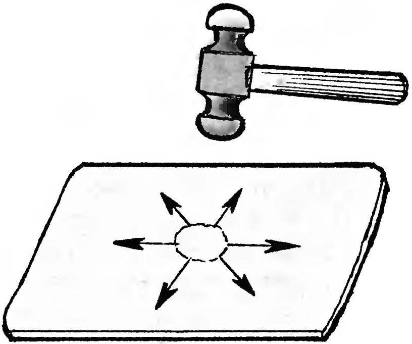
However, the tool can be more complex shapes. Figure 3 shows a special mednitskii hammer. Its damage blows stretch the material radially from the center of the workpiece to the periphery. This tool is suitable for the knockout spherical surfaces — as, for example, bowl, ball surface, the extreme section of the buffer. And on the flat surfaces (hood) this hammer will make unwanted blistering, excessive work hardening of the metal.
In all cases we must strive to the radius of the firing pin is closer to the radius of the part. Figure 4 shows the process of obtaining a bent gutter. The length of the arrows represents the degree of stretching of the metal. When squeezing, first smooth bend middle, with a big bend (or otherwise smaller R3), since the stretching of the sides (R2) it will partially crack. Board of the trough is a large arc, hence, requires more stretching, with the “damping” of the shock to R1. Such details as the mudguard is the same trough, only by bending in the opposite direction (Fig. 5). The workpiece is bent less, because when stretching along the axis of its side compressed. This figure is more time-consuming, and the metal gets more hardening — disturbed internal structure, making the material weaker. Therefore, strive to shocks, especially sharp striker, was weak and lay close to each other. In this case, all the portions of the sheet are subjected to stretching, and thereby the metal gets rid of peretolchina.
Fig. 6. Techniques squeezing in the manufacture of complex segment shapes (“pot”):
1 —the direction of impact for the transverse stretching of the metal; 2—the same for longitudinal stretching on both sides
Fig. 7. Getting a flare on the wing of the car
Fig. 8. So tin beaten out into an Assembly, drawn at a sharp striker:
1—the angle of a cowl; 2—a backing mandrel, for a period punch
Fig. 9. The sequence of receiving the rib on the plane (A—the beginning of the punch, B—completing it):
1 sheet metal; 2—load (bar); 3—fixing sheet nail; 4—bench; 5 —steel area
Fig. 10. Getting sharp edges with a mallet (A—initial drift, B—treatment after the coup and shift of the sheet)
Figure 6 shows a diagram of the squeezing of the segment “pot” (without a bottom). It consists of two previously discussed figures. In the manufacture of smooth cutting is taken and extracts Mednick hammer on a smooth plate. Then pass chute (lower) part of the techniques discussed for figure 4. And so, passing from one section to the other, watching the forming segment.
It happens that the detail of the lead screw. It “POPs” due to internal stresses. But do not be upset and continue to follow a common format, presenting it straightened. Next is “palpated” a hammer on the area that needs stretching, and if the item begins to grow and warp, that there is need to continue to beat. Having experience without “probing” to determine such places.
The above blanks require finishing their outer surfaces and adjacent edges. This is done with a lighter tool, which can serve as a shoemaker’s hammer, which obestochivaete the front side, and is inserted with an inner mandrel supported by the hand. It can be any steel disc with spherical surfaces and ground in 2 — 4 times heavier than the hammer.
Bringing flush adjacent land, not necessarily to beat the other side: stretching and vipassati, he propped up the bar, comes out flush with the adjacent areas. So brought the whole form and its obverse side. This operation is most critical. Having mastered it, people can easily improve (and very skillfully), for example, the surface of the body of the car been in accident.
If the straightening of the eye could not detect the irregularities, then you need a flat file to slightly abrade the surface to detect these irregularities, and then re-align, alternately going back to the previous operations until we achieve a level surface. After finally crisscross apilevel it to a file.
Having reviewed these basic techniques, apply them directly to the wing of the car. To the one shown in figure 7 the scheme of the wing radius R1 and the line flanging, and a section b-B profile in which the radius R0 is the initial, and R2 — after stretching (because he went to a larger radius, and required to stretch).
After this narrow strip And “phototreats”. Here is a partial compression (shrinkage) of the metal. A narrow strip and on a large radius easily sits in the wide part or a small radius of the tin is collected in the Assembly, as shown in figure 8. Assembly sharp striker pull, thereby the metal part like outside shape. Element “X” in figure 7 — the form of the previously considered element of the “pot”.
Ribs vykruchivatsya textolite or wooden (solid wood) with a hammer (faceted, Packed up), as shown in figures 9 and 10. After completing one side of the fin, the wing is set by the other party. Below the sheet is not shifted, it must be in the corners nailed (or squeeze clamps).
In figure 10 the second edge (angle) is treated with a faceted mallet. It bends without much effort. As shown, the sheet bends down slightly with a hand, mallet and tapped on the edge of the bend, instead of spreading the impact into the sheet.
So, after a few times along the edge, the sheet is folded with a simple edge and corner. Turning the sheet the other side, repeat the operation. In the end, the workpiece receives a severe zigzag, which is visible on the wing (section a — A in Fig.8).
To considered, you should add some decorative techniques. Where you want a deep drift, it is convenient (and necessary) detail pre-split, as shown in figure 11. Then each half is made easier. Then they can be welded or riveted. After riveting the front side of the connection is supplied (as in Fig. 12) flush vpaivaetsja (the plaster in such places is no good: it cracks).
Fig. 11. An example of a bulk separation section for easier knockout
Fig. 12. Union sheet metal parts flush:
1 —riveted after punch leaves; 2—rivet; 3—gold; 4—backing bar
Fig. 13. Getting the ribs on the curved surface with the use of the mandrel
Fig. 14. A device for obtaining wydawca:
1 —plot of the sheet with wydawcy; 2 — matrix; 3—part punch
Fig. 15. The stamp for the manufacture of grids:
1 —matrix; 2—perforated sheet; 3—the punch
Fig. 16. Convexo-concave wydawca and an accessory for her:
1—sheet of complex configuration; 2—phase deep wydawcy; 3 — opalocka; 4 — matrix
If you want to label edges on curved or spherical surfaces, they should be performed after the receipt of such a surface technique, shown in figure 13.
Wydawca stiffness of the panel it is convenient to make a special fixture, as shown in figure 14. For this purpose a pair of plates sealed (skatyvaetsya) ends — get a tool like a kind of tweezers. In one foot pre-prepared hole (matrix), the other with a ledge (punch); the gap between them in the thickness of the sheet on which you want to make wydawca. Blow light hammer enough that the panel is trapped between the legs of the fixture, received wydawca.
For the manufacture of grids necessary stamp extractor, the schema of which is shown in figure 15. This can be made from any steel. The holes in the billet happens to the diameter of the stamp. Beaded holes connect logging (Fig. 16) and make the bottom of the lattice. In conclusion, it is desirable to calibrate hole obrabotkami (Fig. 16) and at the same time to squeeze out an extra rib between the grooves.
These are the methods by which in an ordinary shed or garage it is possible to produce individual parts or an entire car body of any desired configuration.
G. VARAKIN, Samara
Recommend to read BALL OF PAPER Plastic body ball point pen is often broken, especially at the tip, near the writing unit. Operational offer a way out: to tighten tight the rod in a paper tube, taped the edge of the... ELECTRONICS: FROM DESIGN TO FILLING It would seem that all good pocket flashlight "Elektronika B6-03": from design to filling, including a fairly capacious battery of three disk accumulators D-0,26. But... As shown by... 
 In my experience that after the publication in the journal “modelist-Konstruktor” home-made car (like mine in the January number for 1971) are the authors of many cities requesting them to share their own experiences. Now, during the crisis, when the possibility of homebrew is limited, I want to help interested readers advice: how, in practice, to restore or to produce the car body with the method of knockout.