
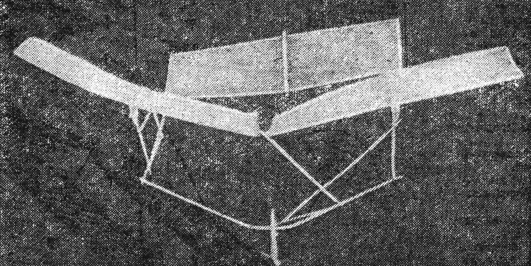
 Room model pricelet really similar to a Hummingbird. This inhabitant of South America — the smallest of the birds — have much to learn. It can still hang in the air and even fly backwards. Our model is no less maneuverable. The design consists of two polycrylic hinged to each other stabilizer, as well as double-girder fuselage, which is attached to the rod with the rubber motor. He drives the crank mechanism polycrylic. Weave wings and stabilizer — capacitor or a tissue paper.
For the construction of the model will need several thin and even the stems of grass or straw 1 and Ø 2 mm, thread, glue BF-2, BF-6 or of AGO, a piece of steel strings Ø 0.3—0.5 mm, the rubber thread a cross section of 1X1 mm and other materials. As can be seen from the kinematic scheme, the point of attachment And the left wing are placed on a fixed pole, and point B is on a swinging pole and the right wing. The last moves left and right in full swing of polycrylic. Both pylons mounted on a transverse rail connecting the longitudinal beams of the fuselage.
First, draw the main parts in full size. Production of the model starts with the Assembly of the fuselage frame with stabilizer from the stems Ø 1-1,5 mm. For connection details and right angle punch in the right place, a thicker stem with a needle and insert it into the hole pointy end is thin. Do not rush to trim off protruding ends of the stems. The connection can be broken and restore it difficult.
When the frame is ready, all the connections seal. The protruding ends of stems cut off, retreating 3-5 mm from the edge. This is necessary so as not to hurt the ligaments. Now bend over the spirit lamp cross rail fuselage frame in the form shown in the drawing. Before this operation the transverse stem wet with water.
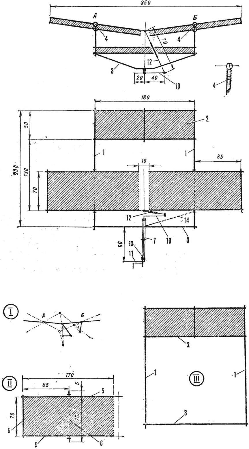
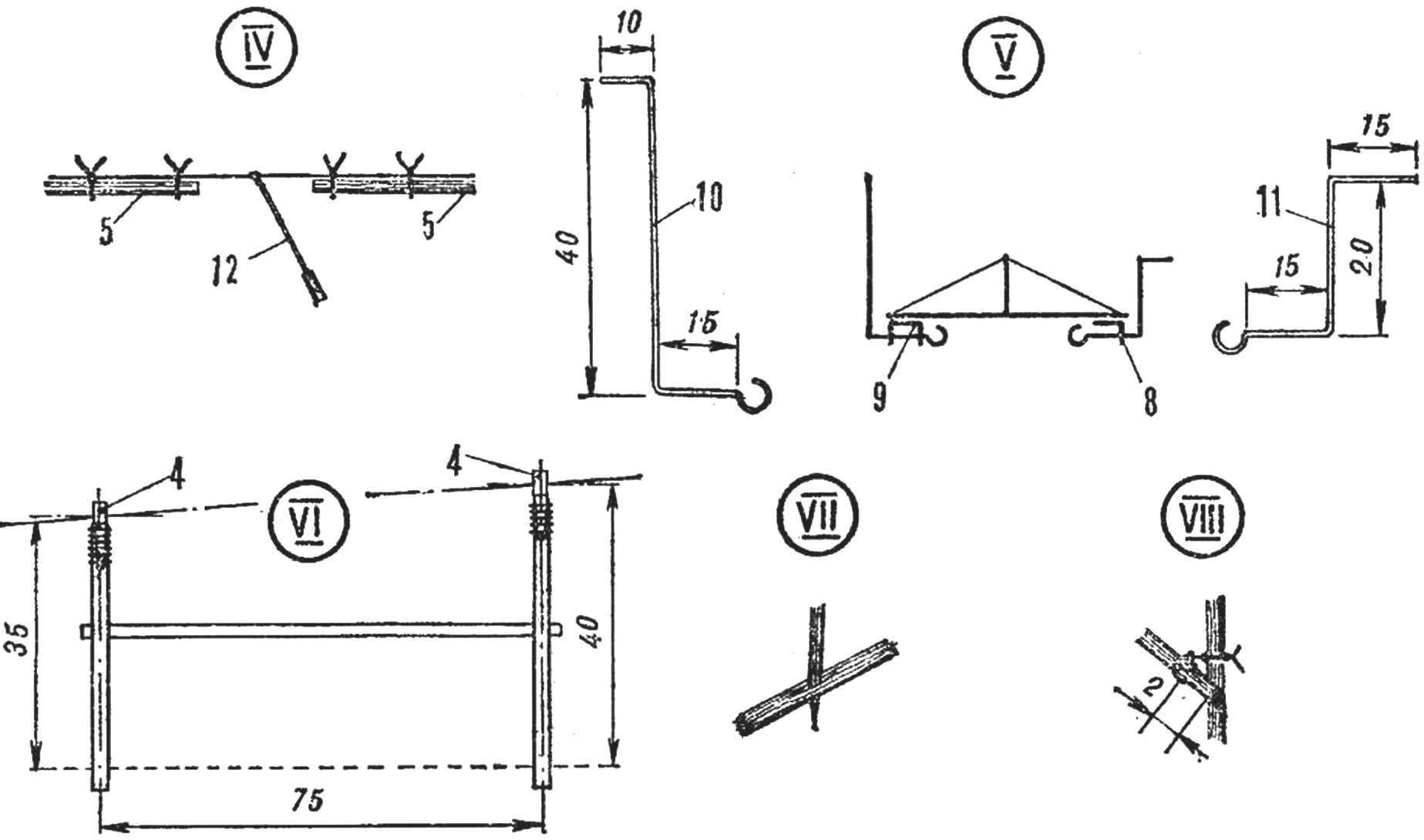
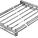
Kinematic and structural layout of the nodes: I. kinematics. II. A diagram of a wing. III. Diagram of fuselage frame with stabilizer. IV. The scheme of fastening polycrylic (leading edge). V. diagram of the motor rail. VI. Diagram of pylon. VII. Fixed connection details. VIII. Swivel parts.
Model “Hummingbird”:
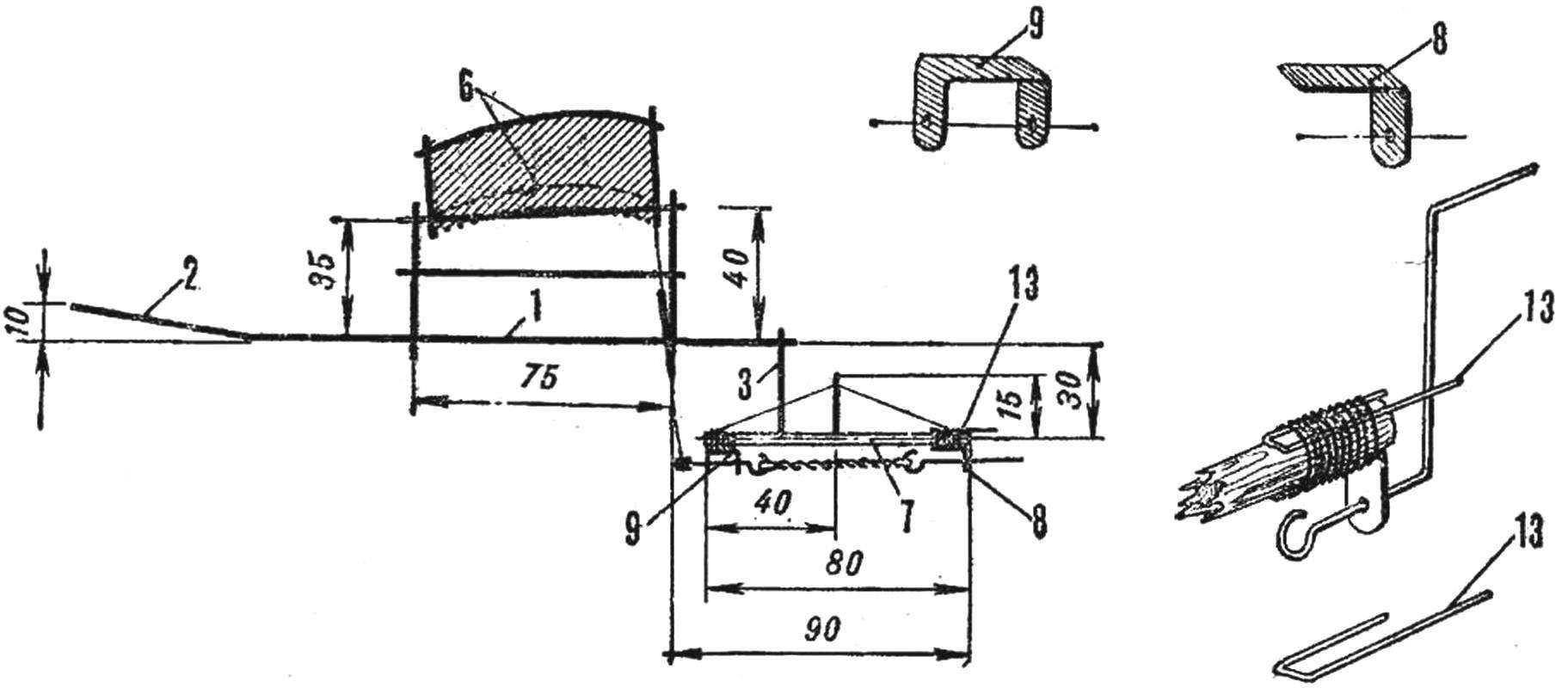
1 — longitudinal beams of the fuselage, 2 — stabilizer S — cross rail of the fuselage, the 4 — lugs on the end slats of the pylon, 5 — edge, 6 — rib wing, 7 is a motor rail of the fuselage, 8 — rear bearing 9 — rear bearing 10 — crank 11 — crank, 12 — rod, 13 — emphasis clockwork handle, 14 — stiffener (if necessary).
Left and right pylons manufacture of stems Ø 1 mm. To the upper ends of the vertical struts attach ears of stiff paper or photographic film, as shown in the drawing. The rear projecting ends of the transverse strips, stems pylons — make a little longer than other compounds. Lateral stems glue only to the front vertical posts. Such a device makes it easy to remove the wing, which is very convenient for repair and transportation model. To install the wing upright push, the protruding ends of the ribs inserted in the holes in the ears.
At a distance of 1-2 mm from the end parts of the pylon B, tie a knot and tie him for another part. This connection it will provide the connectivity and range of motion.VIII.
Recruitment wing consists of edges and two ribs. The last curve in the side view. To take the two edges of the stem Ø 1-1,5 mm, make holes in them with a needle in those places where the ribs are inserted. They protrude beyond the edge of the wing, forming an axis to connect with the pylons. Both halves of the wing are manufactured separately and the hinge seal according to the scheme IV.
The engine (fuselage) rake is the most overloaded part of the model: it perceives the force from the twisted rubber motor. If you make it out of the straw, the ends of the slats close pre-fitted and greased with glue plugs — matches. They need to deepen to primativa bearings, do not squeeze thread the straw. For greater strength motor rail glue two layers of tissue paper.
Front and rear thrust bearings Flex wire or be made of sheet metal, as shown in the figure. Tape the motor rail crosswise thread to the middle of the transverse slats fuselage frame and fill the connection with glue. Next to the motor rail attach the thread with glue the front and rear bearings. The crank winding handle Flex wire. Making a hook for the rubber motor, insert the handle into the front bearing. Then enter in the rear of the crank and bend the hook. Pre-motor rail pierced with a needle, install it from the stem Ø 1 mm upright support and through it thread connect the ends of the slats. This will give the construction more stiffness. A rod end bearing is made of tin film or wire. Detail tape the thread to the connecting rod, which pick up the stem Ø 1.5—2 mm. Thread lubricate the glue. The connecting rod made of two halves and reinforce the tube of straw (paper).
The wing and stabilizer, capacitor glue or tissue paper. The inner part of the wing, shown in the figure: dotted line — without ribs. (Covered with paper of the model in the drawing is shaded.)
Install the wing, and having the ends of the ribs into the holes in the ears of the vertical struts of the pylons. Rod articulated tie a thread to the connection of both halves of the wing IV. Put on hooks crank and crank, the rubber motor in four threads section of 1X1 and start fine-tuning the model. Adjust it to the plan, holding at startup for the connecting rod and the knee crank, changing the installation angle of the stabilizer. Achieving sustainable planning, start the adjustment with motor running. After his spin move the clockwork handle, the head for the focus-lock on the rail. Now carefully take the model for the crank and the connecting rod and push slightly forward. Changing the tilt of the stabilizer relative to the wing until the model flew in a circle.
In the manufacture of “hummingbirds” pay special attention to the operation of the mechanism of flapping wings. If he’s going to stick and slightly shorten the knee crank, bending it a bit or changing the length of connecting rod. If the fuselage, wing and stabilizer will be tough enough in places that the drawing marked with dotted outline fix glue extra stems Ø 0.5—0.7 mm. the Rigidity will increase significantly.
I. TARANUSHENKO, Sevastopol
Recommend to read
 SIMPLE AND EASY
Quick-drying underwear in the kitchen over the gas stove, but there comes a time dining, and hanging over your head, it begins to deliver visible discomfort. And fresh cloth easily...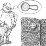 EXTENSION OF… BUTTONS
One has only to afford some indulgences — and now you're does not add up — even buy a new, bigger size. However, there is a way for a while, until you go back to the old weight. Take any...
