
 Perhaps the most difficult stage in the process of creating radiokonstruktor — setting. But if you have even the simplest instrumentation, to establish any electronic device will be much easier. At least, for this job you need avometr, or simply tester. For example, very popular among ham radio uses a simple inexpensive device C-20. But the problem is, he is not entirely comfortable, and this tester is limited. So for those of you who already have such avometr, we propose to improve it by extending the limits of measurement and adding the generator probe with the test transistors.
Diagram of a combined device on figure 1. With the switch set the kind of measurement: AC or DC voltage, DC current, resistance, conductivity type transistors, the capacitance of the capacitor, and using S2 choose the limit of measurement. When measuring voltage in parallel with the microammeter PA1 connects the universal shunt consisting of resistors R15—R20. In position 1(~V) S1 through a rectifier consisting of Diodes V6 and V7, the crown PA1 is supplied pulsating current in one direction.
When the tester is functioning as an ohmmeter, PA1 via the contacts S1 and S2 are connected resistors R12—R14, R21—R26 and the element G2 (when measuring resistances in the position 1X1000 G2 is connected in series with the battery G1). To “zero” the device is set by variable resistor R34 connected in parallel with the microammeter.
The reverse current of the transistors (I to) check is disabled when the output database (switch S3 open). In the closed state of S3 determine the current transfer ratio (h91) semiconductor triode.
Generator probe consists of a high frequency generator and modulator V5 V2—V4, generates electrical oscillations with a frequency of 600 Hz. Oka is determined mainly by the parameters of the chain R4, C2 and R5, C3.
The oscillatory circuit of the generator included in the circuit of the collector of the transistor V5. Its resonance frequency of about 200 kHz determines the inductance of the coil 1.2 and the capacitance of the capacitor C7 (switch S3 open). In this database V5 grounded AC coupled through a capacitor C4.
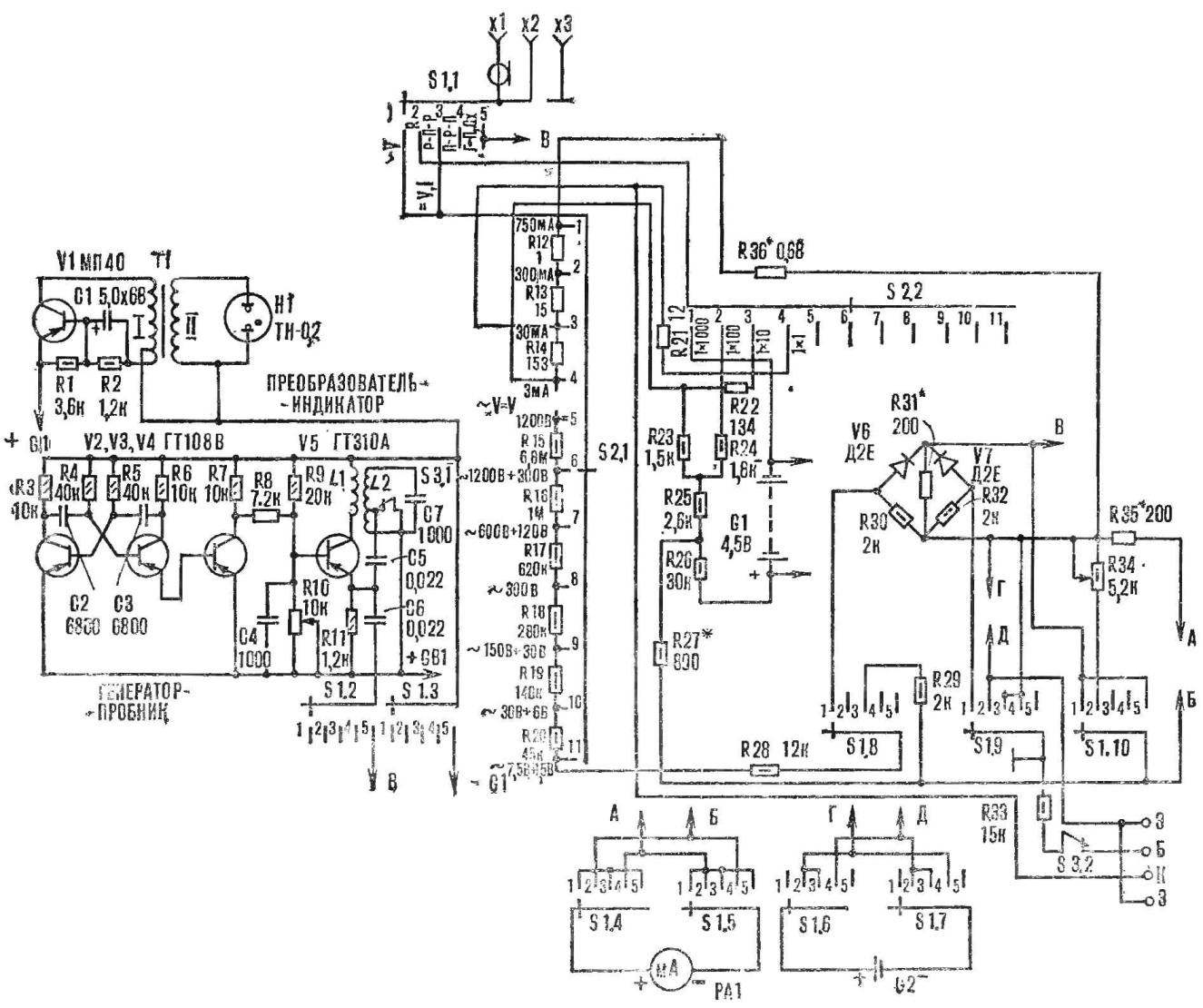
Fig. 1. Schematic diagram of the combined instrument.
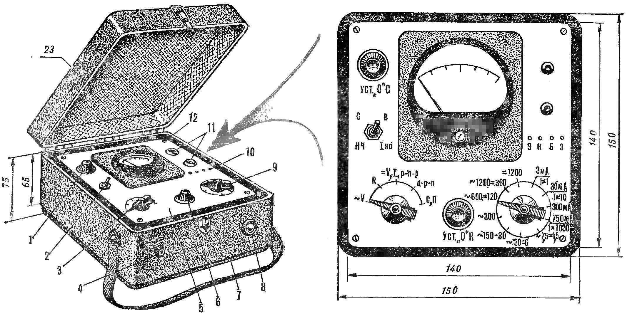
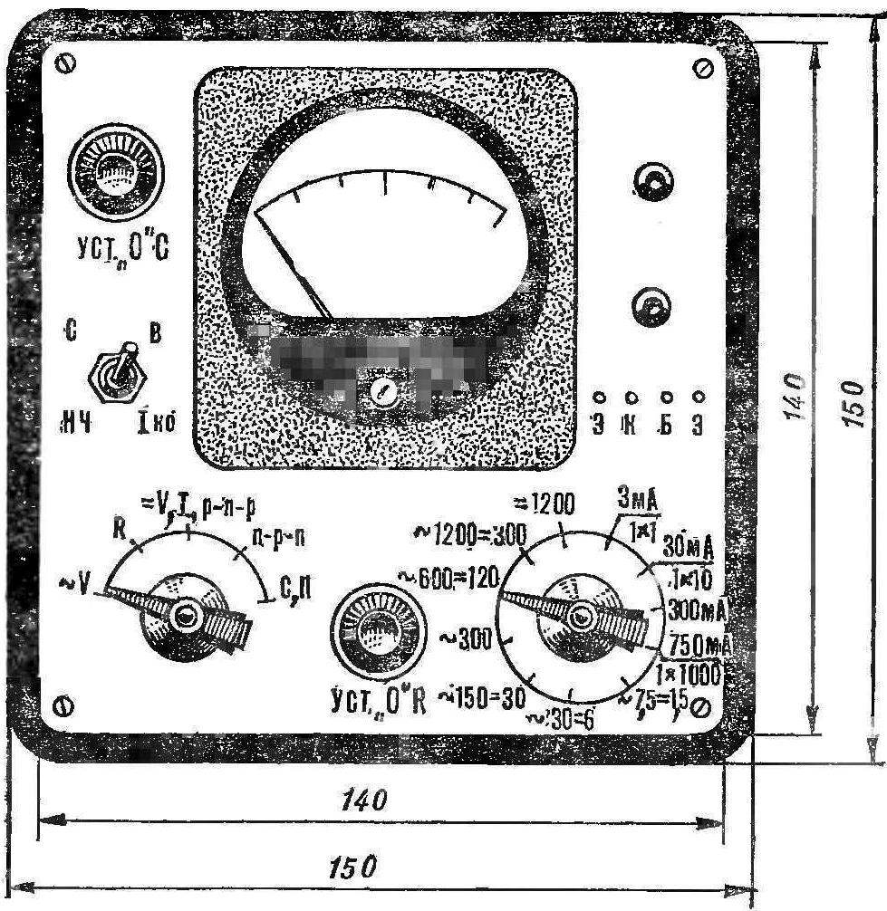
Fig. 2. Appearance:
1 — variable resistor R10, 2 — switch, 3 — S1, 4 — output socket X1, 5 — panel, 6 — variable resistor R34, 7 — bottom cover 8 — neon lamp N1, 9 — switch S2, 10 — socket for checking transistors, 11 — output jacks x2, X3, 12 — screw M2.
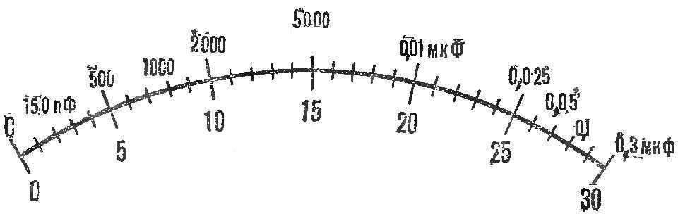
Fig. 3. The scale of the instrument.
The AC voltage from the modulator through the resistor R8 is supplied to the RF generator. The magnitude of the signal to adjust the variable resistor R10, using it simultaneously to install a “zero” when measuring capacity. With the emitter V5 promoborudovanie fluctuations through switch S1 (position 5) are received simultaneously on the ammeter PA1, and outputs X1, x2.
Transistor V1 of the Converter-indicator together with the winding I of the transformer T1 operates in the mode of the blocking oscillator. AC voltage of 70-90 In winding II is supplied to the neon lamp N1.
The structure is assembled in a plastic case with a hinged lid (Fig. 2). Front panel is made of Plexiglas with a thickness of 2-3 mm. Sockets for connection of the transistors serve as caps. Using the hot soldering iron to press them in plexiglass.
Lamp H1 is fixed on the front of the case with glue BF-2 and protected by a transparent cap. The resistors are mounted on the mounting bars (Fig. 4) attached to the inner side of the front panel using standoffs and screws M2. Under them in the holes on the panel is threaded.
Generator probe is mounted on a printed circuit Board made of foil Micarta (Fig. 5). To help minimize interference, it is placed in the screen, representing two or three layers of aluminum foil connected to the “minus” of the battery.
The bottom case cover is removable. On the inside of her mounted clamping band of flexible plastic power sources G1 and G2.
The device uses a microammeter М494 or any other with a current full deflection 50-80 µa. S1 and S2 — app switches for 5 and 11 positions, respectively, S3, the switch TP1 — 2.
Resistors R12—R14, R21, R22, R31, R35, R36 wire-wound manganin or konstantinovoj wire Ø 0,1—0,15 mm, on frames from resistors VS-to 0.5 (after they remove the conductive layer and the paint with acetone).
Finally the resistances are chosen configuration process using industrial avometr. R3—R9, Rll—MLT-0,125 or MLT-0,25. Other fixed resistors MLT-0,5. Variable resistors R10 and R34—SP-1. They can be replaced for GPA-12 or SPO-0,4. C1 capacitor electrolytic K50-6, K50-3 K50 -; S 2, Sz—Н70; C4, C7— KM-4; S5, S6 — BM. You can replace all small capacitors of the corresponding capacitance.
Instead of transistors MP40 and ГТ108В suitable МП39—МП42, МП26 with In=20-40, and instead ГТ310А suitable П402, П403, П416, ГТ313 with A=40-60.
G1 — battery “ruby” or 3336L. G2 element 316, 286, or 314. In addition to T-0,2, the device can be set to “neonka” TN-0,95 or T-30.
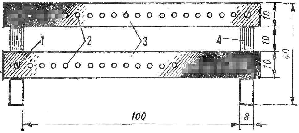
Fig. 4. Circuit Board for mounting the resistors:
1 — M2 screw, 2 — hollow rivets, 3 — getincome strap, 4 — front (S plexiglass 3 mm).
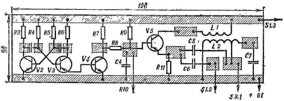
Fig. 5. The printed circuit Board of the generator probe with the location details.
The transformer T1 is small, the matching from every pocket transistor radio; the secondary winding of the need to rewind. Here is his data. The core is recruited from the plates Ш3Х6. I winding contains 120 turns of wire sew-1 0.2 s withdrawal from 20th round. The winding II has 1500-2000 turns of wire sew-1 0,06—0,09.
The L2 coil contains 300 turns of wire PEV-1 0,1 with the withdrawal of the 20-th round. On top of it, the coil L1 is wound with 40 turns of PEV-1 0,1. Frame 0 5 mm, length 20 mm Core — ferrite brand 600НН length 10 mm, Ø 2.8 mm.
Configuration of the combined device is to customize the behavior of individual nodes, dividing the ka scale heads (Fig. 3).
First of all, set the ammeter to zero by adjusting the resistance of the wire resistor R35 with synchronous adjustment of the engine variable resistor R34. Next, using the reference resistors with deviations from the nominal value, not exceeding 15%, comparing the readings with industrial. The fit of the scale produced by using the resistors R21, R22, R27.
Exemplary and working on the devices set to measure DC current, and then include them consistently to both the arrow of the microammeter is deflected in one direction. Selecting the values of resistors R12—R14, and achieve accuracy of reference currents for each scale of 0-3 mA, 0— 30 mA, 0-300 mA, 0-750 mA.
Now both devices set to measure DC voltages. The regulated output voltage of the rectifier are connected to respective sockets of the voltmeter, adjusting the readings of the custom device by adjustment of the resistors R15 to R20.
Further, the instrument switches to the measuring position AC voltage and is connected to Lotro. By adjusting R31 set the operation mode half-wave rectifier.
Because a universal shunt consisting of resistors R15—R20, picked up by the DC voltage, it only slightly corrected by changing slightly the values of the resistors. Constantly monitor the readings on the scale of DC voltage. To simplify the process of establishing a universal shunt resistors in each limit measurement consists of two, connected in series. For example, R20 recruited from 43 ohms and 2 ohms. A resistor with a smaller value, thus, it would be fitting.
The establishment of the generator probe is reduced to the setting circuit for the frequency of 200 kHz, a ferrite core. Roughly configure the device scale of the radio corresponding to the wavelength range (1500 m).
A. MEDVEDEV, G. Krasnoperekopsk
Recommend to read
 AND PAINT, AND LACQUER
Few people know that packaging Styrofoam is the perfect base for the manufacture of varnishes and paints. The first are obtained by dissolving the foam in solvent "647" or butyl acetate.... “MERCENARIES” — NAKED AND IN ARMOR
We have already talked about the fact that the Mediterranean powers, France and Italy after the First world war were almost no modern cruisers scouts that were at the end of battles is...
