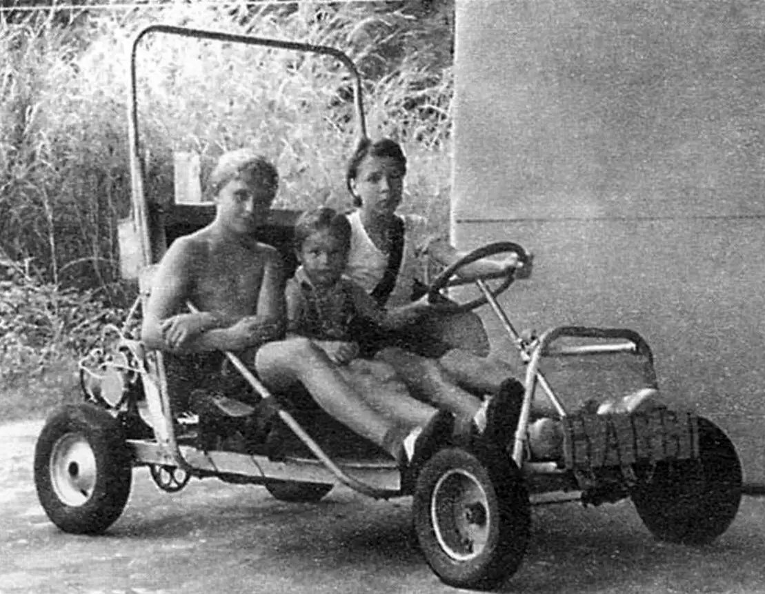
Boys seem to have a natural pull toward technology — probably something embedded in their genes. Yet, there’s a fairly long period in their lives (that so-called “transition age”) when they consider playing with toy cars too childish, but driving a real car is still not an option — and often, not even available to their parents.
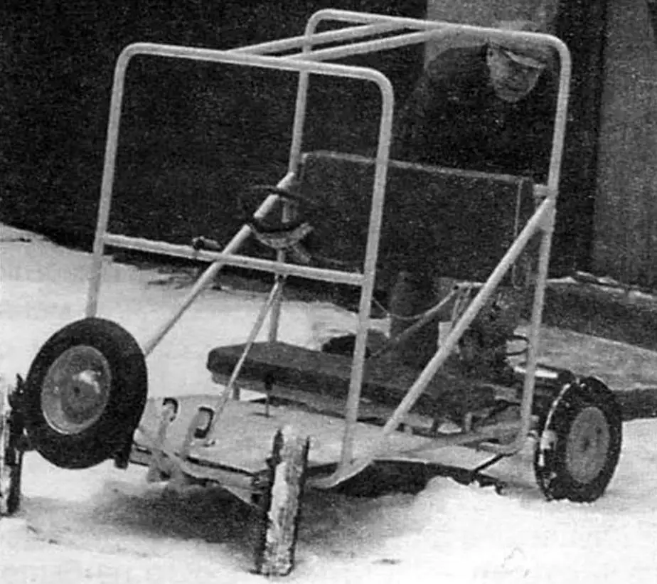
So, with boys like that, we’ve designed and built several simple yet real cars, differing slightly in size and design. That’s why we called the larger ones “buggies,” while their smaller “siblings” were referred to as “karts.”
We decided to share one of these vehicle designs with the readers of Modelist-Konstruktor magazine, especially since we used a lot of the information and ideas from it during the development process.
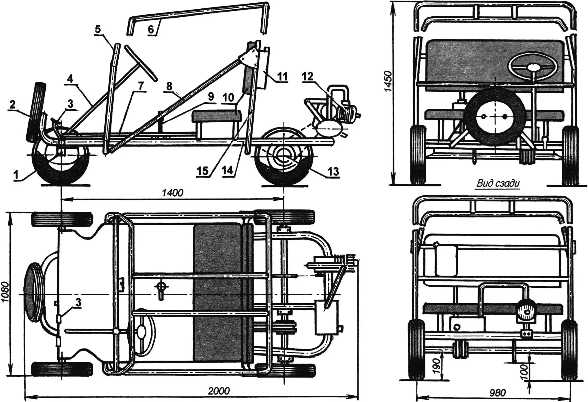
1 — steering knuckle; 2 — wheel (from a garden cart, 5 pcs.); 3 — control pedals; 4 — steering mechanism; 5 — front safety hoop; 6 — connecting strut (2 pcs.); 7 — floor (plywood s6); 8 — brace (2 pcs.); 9 — clutch disengage lock handle; 10 — seat (bench and backrest); 11 — fuel tank (5L plastic canister); 12 — power unit; 13 — rear axle; 14 — frame; 15 — rear safety hoop
The proposed vehicle is structurally similar to a go-kart and consists of the following assemblies and components: a power unit with control mechanisms, a frame with safety hoops, a front axle with guide wheels and steering, a rear axle with a driven right wheel, chain drive, and friction brake assembly.
Incidentally, I hold a patent certificate for the design of the drive axle and the friction brake assembly.
The car’s frame is welded from thin-walled round steel tubes made of medium-alloy steel with good weldability (e.g., 30KhGSA steel, which is widely used in bicycle frames and public transport handrails).
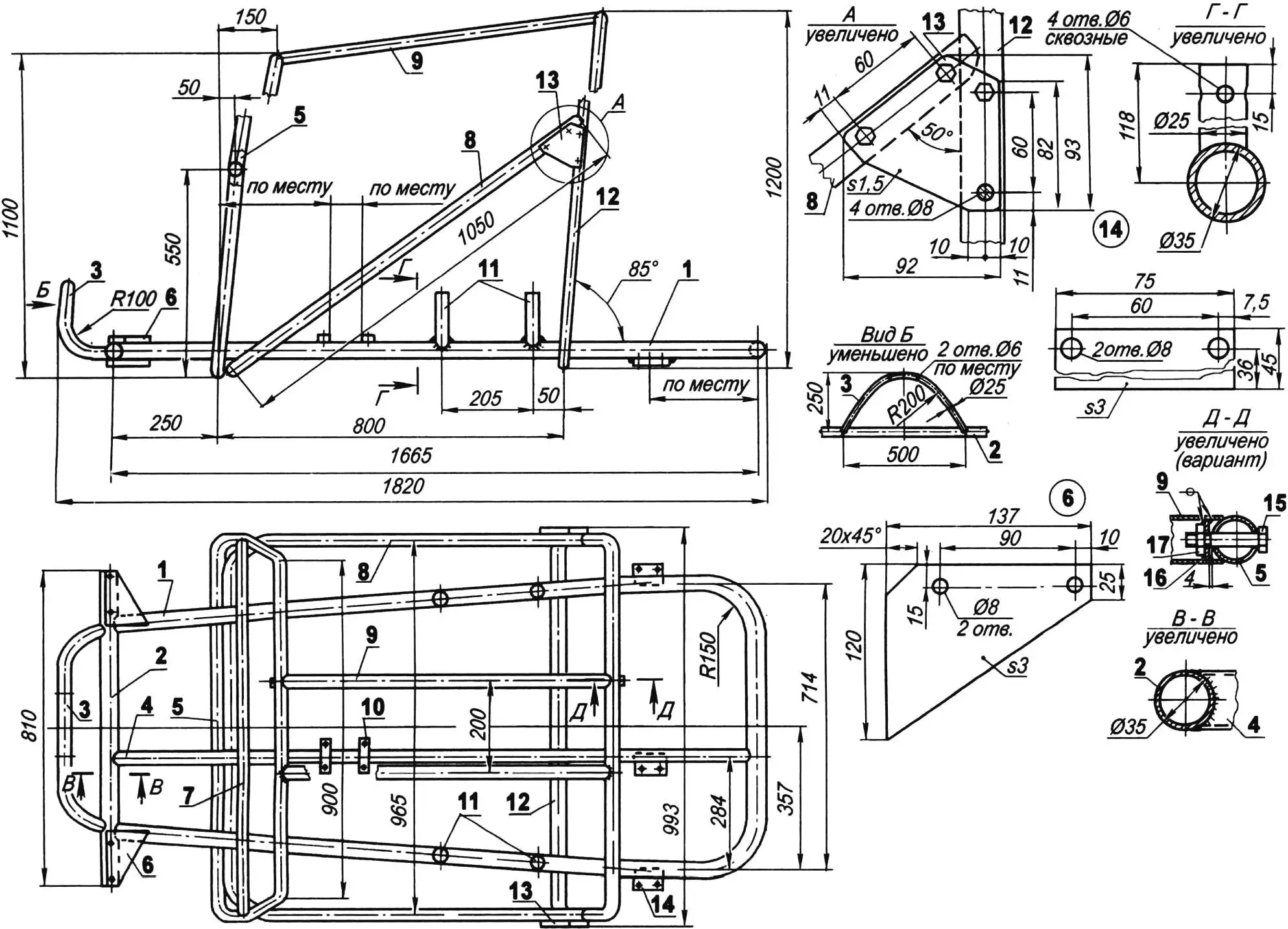
1 — main side member; 2 — crossbeam; 3 — spare wheel support; 4 — intermediate side member; 5 — front safety hoop; 6 — gusset (St3, 3mm sheet, 2 pcs.); 7 — crossbar; 8 — brace; 9 — connecting strut for hoops (2 pcs.); 10 — clutch lock support bracket (St3, 5mm sheet, 2 pcs.); 11 — seat posts (4 pcs.); 12 — rear safety hoop; 13 — overlay plate (St3, 1.5mm sheet, 2 pcs.); 14 — rear axle housing bracket (St3, 3mm sheet, 3 pcs.); 15 — M8 bolt; 16 — washer; 17 — M8 weld nut
The total length of the thickest tubes (35 mm outer diameter, 2 mm wall thickness) used for the frame is about 6.5 meters, and the thinner tubes (25 mm diameter) amount to around 17 meters. Frame parts can be welded from sections and finished by grinding the circular seams. The pipe blanks were bent cold using a pipe bender. For angled joints, the ends of the “joining” tubes were ground to match the radius of the “receiving” tubes. Without such matching, achieving a strong weld is difficult even for a professional.
Alternatively, the frame can be made from duralumin profiles (e.g., D16 or D19 alloys), but that would require argon arc welding. Such a frame will be lighter but more expensive.
Frame assembly begins with the fabrication of the main parts — the side members and crossbeams. The main side member blank (bent from a 3/4″ pipe and consisting of a right and left arm and a rear buffer between them) is 4 meters long with both bend radii at 150 mm. Assembly is done on a flat horizontal surface or jig. The parts’ positions are aligned precisely using a square and tape measure, following the blueprint.
After alignment, the components are tack-welded in several spots. Measurements, symmetry, and parallelism are rechecked. If needed, parts are repositioned, then permanently welded. The crossbeam ends are closed with caps. Next, the safety hoops and braces are set into place — first tack-welded and adjusted, then firmly welded to the side members. Connecting struts are then welded between the hoops.
If storage height is an issue, the attachment of the safety hoops and braces to the side members, as well as the hoops to each other, can be made detachable using M8 bolts. In this case, corresponding through-holes must be drilled in both connected parts. The connection between the front and rear hoops using struts at the top is also bolted, as shown in the illustration. The lower end of the brace is better attached to the front hoop rather than the side member.
Next, seat posts can be welded to the side members, and the buffer to the crossbeam. Other brackets, supports, and gussets are best welded during the installation of their respective assemblies.
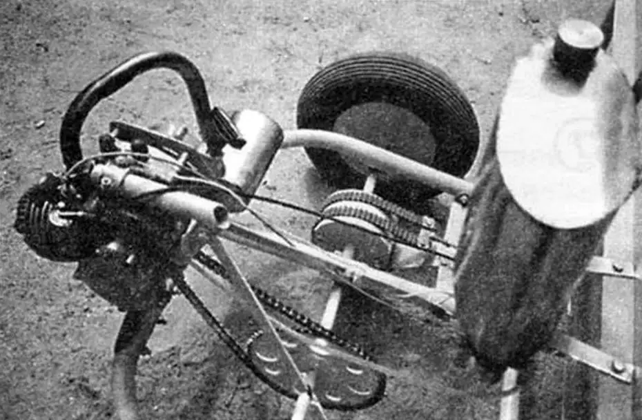
As the power unit, we used a D8M moped engine rated at 1.1 hp with up to 5000 RPM, but another engine from the “D” series can also be installed. However, using a more powerful engine is not recommended — even this one allows the car to reach speeds of up to 25 km/h.
The engine is mounted behind the driver’s seat on the right side. It is attached to the frame using a removable corner bracket (subframe) made from two Ø25 mm tubes — a console and a support post.
The bracket post is welded to a mounting plate, which is bolted to the rear cross-section of the side member (the frame buffer) using three M8 bolts. The plate is made from 3 mm thick St3 steel sheet. Horizontal through-holes in the side member are drilled using the plate as a guide.
The engine is installed with the cylinder head facing backward and tilted slightly downward. However, the carburetor is mounted vertically — this was achieved by rotating its housing slightly within the mounting port before securing it again.
The engine is started with a manual starter from a Ural chainsaw. A custom adapter with a ratchet was screwed onto the magneto shaft to fit the starter. The ratchet is covered with a modified cap from the same chainsaw. The ignition cut-off switch is mounted on a small dashboard fixed to the crossbar of the front safety hoop, to the right of the driver.
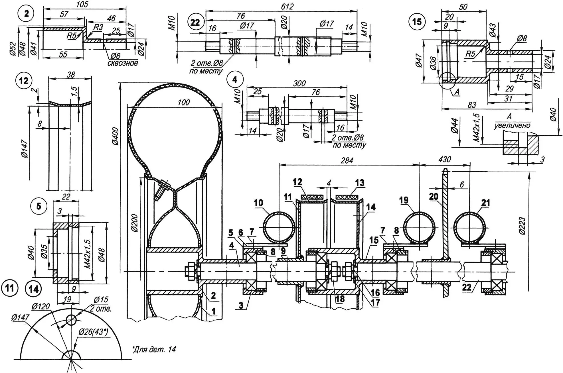
1 — wheel (2 pcs); 2 — wheel hub (St3, Ø52 bar, 2 pcs); 3 — bearing (80203 or 180203, 4 pcs); 4 — left axle shaft (St3, Ø20 bar); 5 — bearing housing (St3, Ø50 bar, 3 pcs); 6 — bearing housing base (St3, 2 mm sheet, 3 pcs); 7 — bearing housing mounting bracket (3 pcs); 8 — special nut M42x1.5 (St3, Ø42 bar, 4 pcs); 9 — support sleeve (St3, Ø30 bar, 2 pcs); 10 — left frame rail; 11 — left brake drum disk (St3, 2 mm sheet); 12 — brake drum rim (St3, 37×1.5 mm strip, 2 pcs); 13 — brake band (belt from VAZ-2108); 14 — right brake drum disk (St3, 2 mm sheet); 15 — special sleeve (St3, Ø47 bar); 16 — spring washer Grover (4 pcs); 17 — thrust washer (22x11x2, 4 pcs); 18 — nut M10 (4 pcs); 19 — center frame rail; 20 — drive sprocket of the driving wheel (pitch = 12.7, teeth = 55); 21 — right frame rail; 22 — right axle shaft (St3, Ø20 bar)
The engine cylinder is integrated with the housing, which contains the clutch and reduction gear. From the sprocket (z = 9) on the output shaft, torque is transmitted by a chain to the drive sprocket (z = 55) on the right axle shaft of the rear axle. This shaft is mounted in two support bearings whose housings are fixed to the middle and right main frame rails. The chain has the same pitch as most bicycles — 12.7 mm — but the sprocket thickness (and thus the gap between the chain link cheeks) is greater — 6 mm.
The right axle shaft is connected to the left one via a special sleeve. One end of the sleeve is rigidly fixed to the right axle shaft, and the other is mounted on the outer ring of a bearing, whose inner ring sits on the left axle shaft. The right brake drum disk is also mounted and welded to this sleeve. The left brake drum is rigidly fixed on the left axle shaft via another sleeve.
Braking is performed by friction from rubber belts that wrap around the outer surfaces of the brake drums when the driver presses the corresponding pedal. During movement, the belts simply glide over the drum surfaces.
In challenging conditions, such as mud or icy roads, the brake drum disks can be connected using two M8 studs inserted into special holes, making the left rear wheel also a drive wheel.
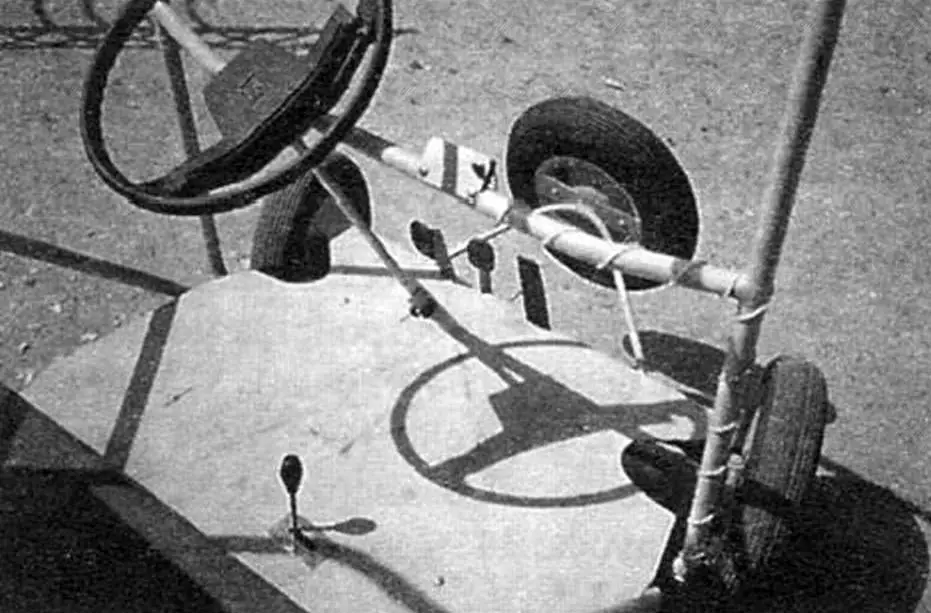
The vehicle’s guide wheels are at the front. Steering is controlled via the steering wheel and shaft, connected through a gear-rack mechanism, rods, and steering knuckles. The steering system is simplified, but it provides synchronized turning of both front wheels.
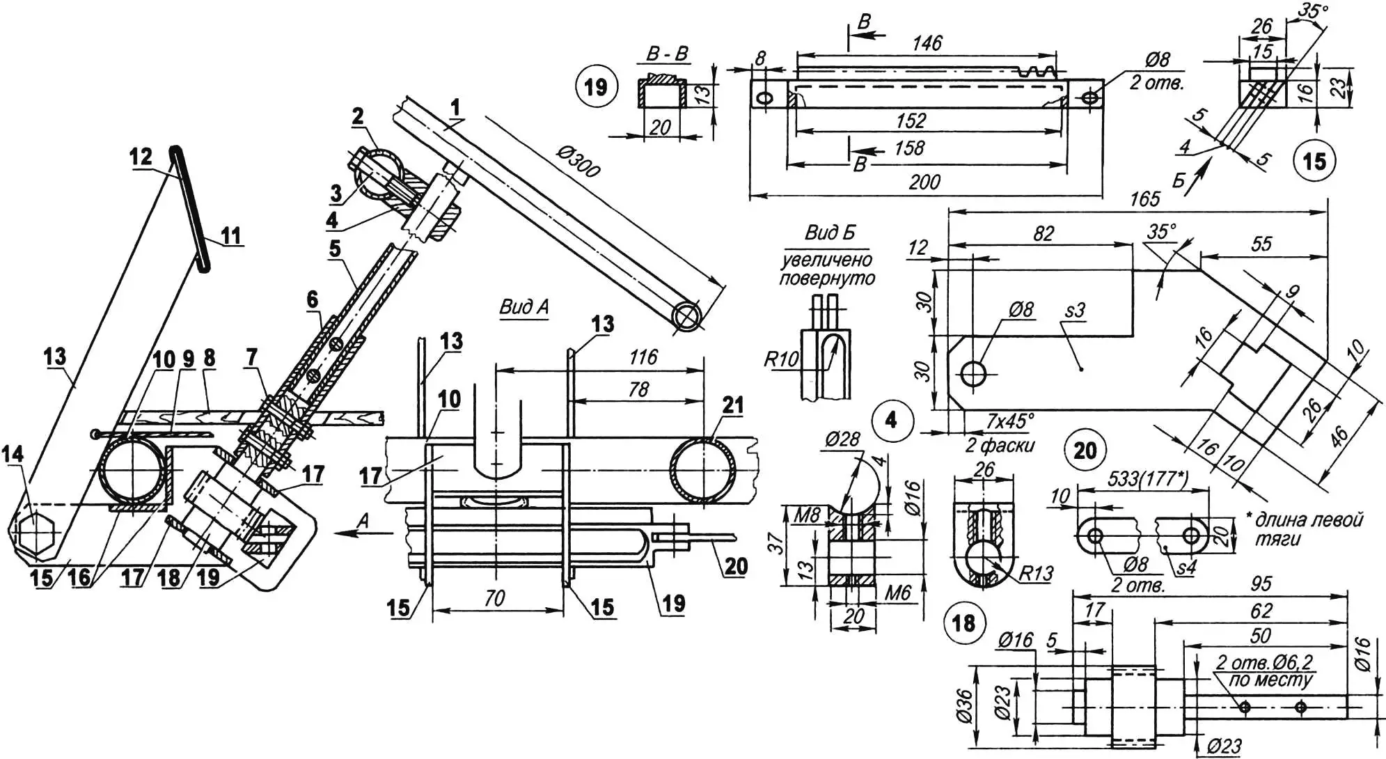
1 — steering wheel (from Zhiguli car); 2 — front roll bar crossmember; 3 — M8 set screw; 4 — steering shaft bracket (bronze); 5 — steering shaft (St3, Ø16×2 pipe, L640); 6 — locking sleeve (Ø16 inner pipe); 7 — M6 bolt (4 pcs); 8 — floor; 9 — clutch cable; 10 — front crossmember; 11 — pad (rubber, 2 pcs); 12 — pedal (St3, 2 mm sheet, 2 pcs); 13 — pedal arm (St3, 5 mm sheet); 14 — pedal arm shaft (brass, hex Ø27, 2 pcs); 15 — steering brackets (St3, 3 mm sheet, 2 pcs); 16 — flanges (St3, 3 mm sheet, 4 pcs); 17 — gear supports (St3, 3 mm sheet); 18 — gear shaft (m = 3, z = 0); 19 — rack (30ХГСА steel, m = 3, z = 15); 20 — rod (St3, 20×4 strip, 2 pcs); 21 — intermediate frame rail
The steering wheel and shaft were borrowed from an old Zhiguli. All other steering components are homemade, although the gear can be store-bought.
The gear (z = 10, m = 3) is fixed to the steering shaft end via a sleeve and four pin bolts (two on the shaft, two on the gear hub). Rotation of the gear causes linear motion (left or right) of the rack, which has rods attached on both sides. The other ends of the rods are connected to the steering knuckle arms, which are in turn connected to the wheel axles.
The kingpins of the steering knuckles are attached to the ends of the front crossmember using two M8 bolts each.
All steering knuckle parts are made from 30ХГСА alloy steel: the kingpins are milled, and the remaining parts are turned on a lathe, with flats and square shapes filed manually.
1 — front crossmember; 2 — kingpin; 3 — lever (Ø17 rod); 4 — pivot pin (hex Ø17); 5 — axle (Ø20 rod); 6 — hub (Ø52 rod); 7 — spacer sleeve (Ø23×3 pipe); 8 — bearing housing (Ø48 rod); 9 — bearing 180203 (2 pcs); 10 — wheel (from garden cart)
When making axles, hubs, and custom nuts, it is crucial to ensure high precision and surface finish to accommodate the bearings. It’s best to outsource these parts, as well as the rear axle and gear components (if a ready-made gear isn’t available), to professionals. Wheels can be purchased — even those from a garden cart will work.
The engine muffler is homemade. The stock one is too loud and bulky for such a small car.
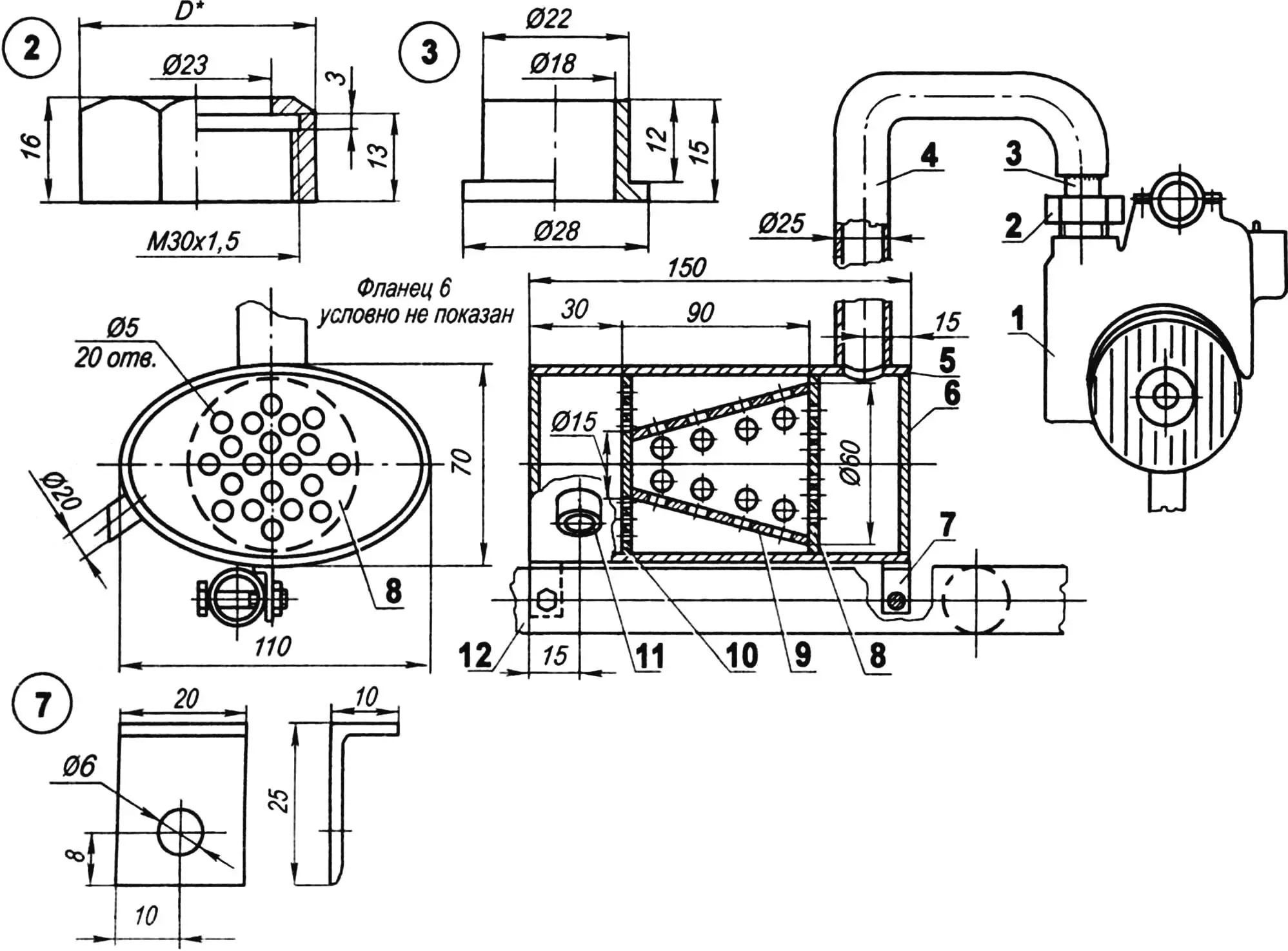
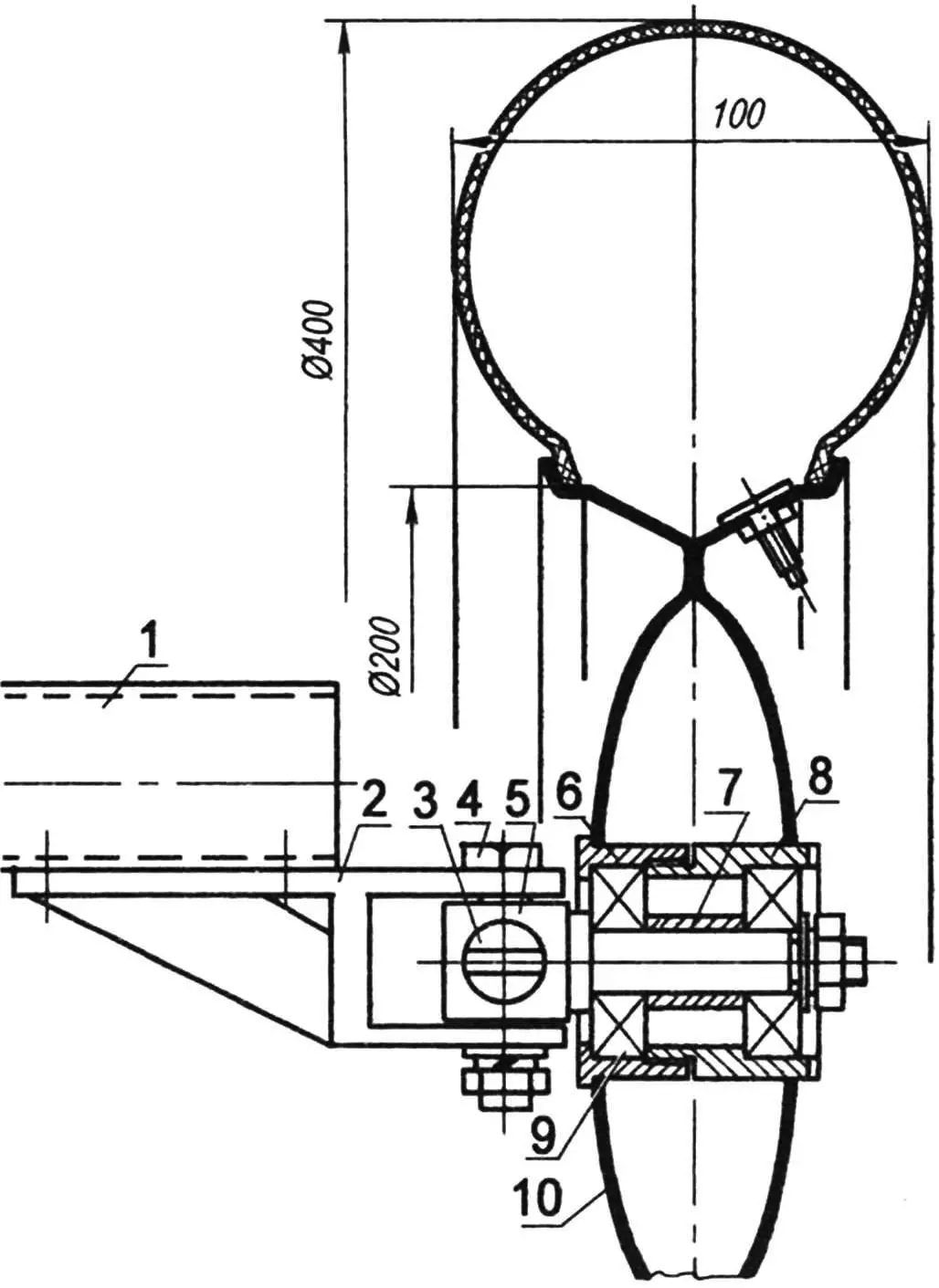
1 — engine; 2 — union nut 30×1.5 (St3, hex Ø36); 3 — nipple (St3, Ø28 rod); 4 — Ø25 connector pipe; 5 — muffler shell; 6 — shell flange; 7 — bracket (steel angle 25×10, 2 pcs); 8 — first baffle; 9 — conical baffle; 10 — second baffle; 11 — exhaust pipe (Ø20×1, L25); 12 — rear frame bumper
The muffler body is barrel-shaped with four chambers, and elliptical flanges measuring 110 mm by 70 mm. The chambers are separated by two flat baffles and a truncated cone section (the cone layout should first be made from cardboard). Each baffle and the cone have 20 evenly spaced holes, 5 mm in diameter. All parts are made from 1 mm stainless steel sheet, though St3 steel can also be used.
A thin-walled exhaust pipe Ø25 mm and ~0.5 m long connects the cylinder to the muffler. One end is welded to the input chamber of the muffler shell, the other to a nipple with a union nut, for connection to the cylinder. The final chamber also has an outlet — a short Ø20 mm pipe is welded here as the exhaust tip.
The muffler body is attached to the rear frame bumper using two M6 bolts and two small steel brackets welded underneath the shell.
The D-8M power unit includes a built-in clutch mechanism that allows the engine to be temporarily disconnected from the transmission. This makes it possible for the little car to remain stationary with the engine running and also allows the engine to be started from a standstill, without needing a push start. The clutch on the car is disengaged just like in a real vehicle—by pressing the pedal located on the left side of the steering shaft, on the floor.
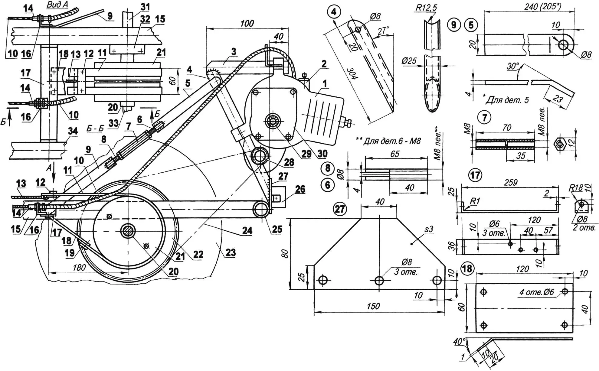
1 — engine; 2 — carburetor; 3 — subframe console (Ø25 pipe); 4 — subframe upright (Ø25 pipe); 5 — upper strut section (St3, 20×4 strip, 2 pcs); 6 — M8 turnbuckle threaded rod (St3, Ø8 round, 2 pcs); 7 — M8 turnbuckle threaded sleeve (half with left-hand thread); 8 — M8 threaded rod, left-hand (St3, Ø8 round, 2 pcs); 9 — lower strut section (St3, 20×4 strip, 2 pcs); 10 — clutch and throttle control cables (Ø3); 11 — brake belts (from VAZ-2108 timing mechanism, 2 pcs); 12 — brake belts and cable joint; 13 — brake drive cable (Ø3); 14 — M6 special screws for clutch and throttle adjustment (hex head for 10 mm wrench); 15 — middle frame longitudinal member; 16 — brackets for throttle and clutch cable adjustment screws (20×20 aluminum angle); 17 — bracket-shelf (St3, 2 mm sheet); 18 — brake belt spacer (St3, 1 mm sheet); 19 — brake belts and spacer joint (20×20 washer plates with Ø6 hole, St3, 1.5 mm sheet); 20 — support sleeve; 21 — brake drum (2 pcs); 22 — drive sprocket of driving wheel (t = 12.7, z = 55); 23 — rear right driving wheel Ø400; 24 — drive chain (t = 12.7, L = 1000); 25 — rear bumper of the main longitudinal member; 26 — high-voltage transformer TLM-3; 27 — subframe support plate (St3, 3 mm sheet); 28 — drive sprocket of the engine output shaft (t = 12.7, z = 9); 29 — ratchet (from Ural chainsaw); 30 — mechanical start device cover (from Ural chainsaw); 31 — right half-shaft; 32 — rear axle bearing housing bracket (3 pcs); 33 — left half-shaft; 34 — left longitudinal member
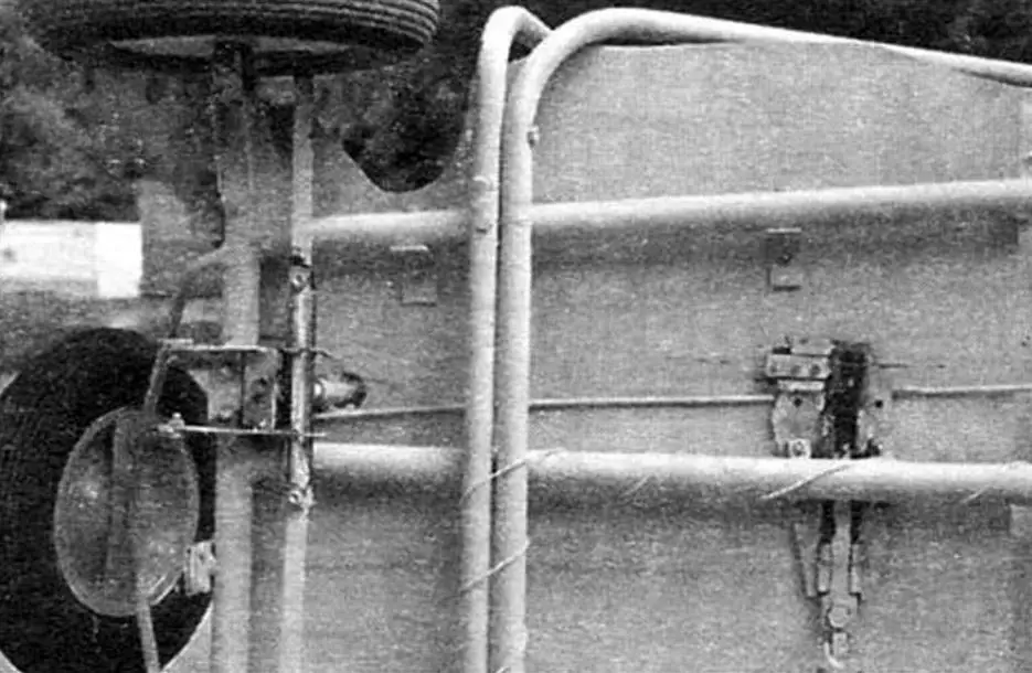
However, it’s nearly impossible for one person to hold the clutch pedal while starting the engine. It’s also not possible to get out of the car without shutting the engine off. To eliminate these inconveniences, a device was made to lock the clutch in the disengaged position.
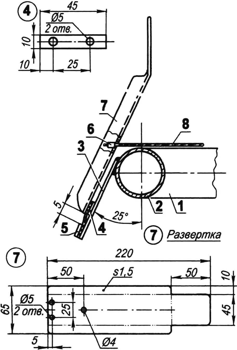
At the heart of this device is a plate made of 2 mm thick stainless steel with a blank size of 220×110 mm. If stainless steel is not available, St3 steel can be used. Six guides are made of bronze (or brass). They are each attached to the plate using two M5x10 screws so that the slider and latch move freely but without play. The slider with its pad and the latch are made from 3 mm thick 30KhGSA steel sheet.
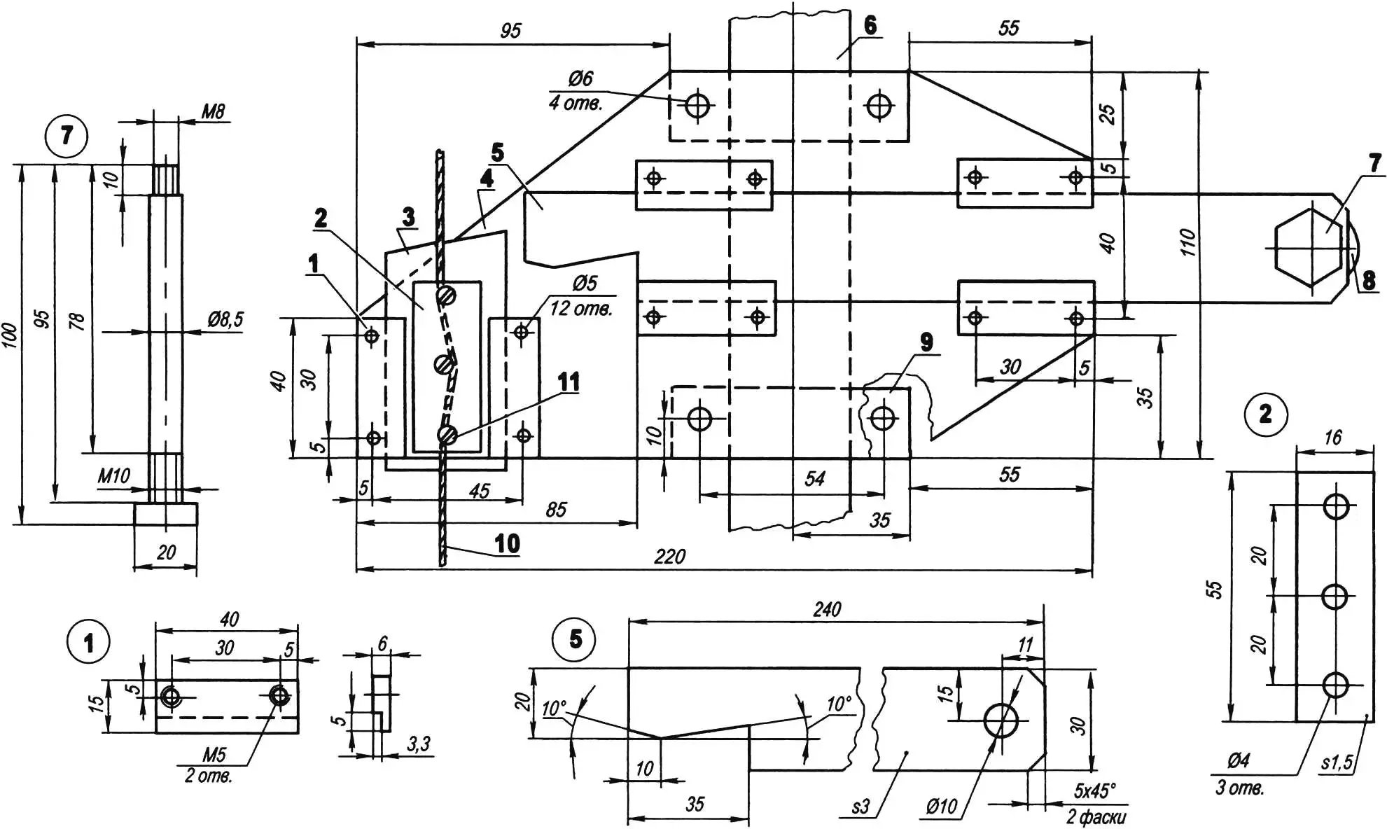
1 — guide (brass or bronze, 6 mm sheet, 6 pcs); 2 — pad (30KhGSA steel, 1.5 mm sheet); 3 — slider (30KhGSA steel, 3 mm); 4 — base plate (stainless steel or St3, 2 mm); 5 — latch (30KhGSA steel, 3 mm); 6 — middle frame longitudinal member; 7 — handle post (steel hex rod for 17 mm wrench); 8 — handle (automotive gear shift lever with M8 threaded blind hole); 9 — frame support (2 pcs); 10 — cable Ø3; 11 — M4 screw (3 pcs)
The M4 threaded holes in the slider should be marked at the same time as the non-threaded holes in the pad. The holes in the pad should also be countersunk on one side for flush screws that clamp the clutch cable between the slider and pad. This cable runs from the pedal to the engine housing. The screw ends sticking out from the latch should be filed flush and the surface polished for smooth sliding on the plate.
The handle post is machined from a hex rod for a 17 mm wrench. It is inserted into a hole in the latch and secured with an M10 nut and spring washer. You can use an automotive handle or make one yourself from plastic or wood.
The assembled mechanism is mounted on supports on the middle frame longitudinal member.
All friction surfaces and threaded holes must be lubricated with thick grease during assembly.
The accelerator pedal is a bit different from the clutch and brake pedals. Its blank is cut from 1.5 mm thick St3 steel sheet, with the edges bent for rigidity.
1 — middle frame longitudinal member; 2 — cross beam; 3 — bracket (St3, 2 mm sheet); 4 — pad (St3, 1 mm sheet, 2 pcs); 5 — hinge (rubber strip 45x25x3 mm); 6 — clamp (lead seal); 7 — pedal (St3, 1.5 mm sheet); 8 — cable (Ø3)
The two pads are also cut from 1 mm thick St3 sheet. A rubber strip measuring 45x25x3 mm acts as a hinge. The pedal is connected to the bracket through this strip, and the bracket is welded to the front cross beam on the right side of the steering shaft. The gap between the brake and accelerator pedals should be at least 70 mm. The end of the throttle cable is inserted into a hole in the pedal and fixed with a clamp.
A ready-made fuel tank is easy to find—even a thick-walled plastic canister (3 to 5 liters) from automotive fluids will work. Install a fuel valve in the bottom of the tank and connect it to the carburetor using a fuel-resistant hose.
The tank should be mounted behind the seatback, but its bottom must be higher than the carburetor for gravity-fed fuel flow.
Seats can be repurposed from other vehicles or made from scratch. The seat and backrest should both measure 850×300 mm. Use 5–6 mm thick plywood as a base. Glue foam rubber or polyurethane foam to the plywood, cover it with faux leather, and hang a nylon net between the seat and backrest. For safe operation, the drive chain and sprocket should be protected with a cover like those used on mopeds.
It would be great to also equip the car with a parking brake. To do this, the pedal mechanism should include the same kind of locking device used in the clutch system.
Finally, all steel parts of the frame (except those made of stainless or non-ferrous metals) should be painted. Before painting, clean off all rust, degrease, and apply primer. It’s best to use bright paint and apply it with a spray gun.
A. MAGON
Recommend to read
 MAN-MADE BIRD “ALBATROS”
The peak of development of hydroaviation was in the middle of the 1930-ies. The main advantage of amphibians compared to ground vehicles, flying over extensive areas, it was considered a... IMPROMPTU BATH
Often, especially in the repair associated with coloring, voznykaet need to vanocnich, that is to say, disposable. Nothing could be simpler: take any box and cover it with plastic wrap...
