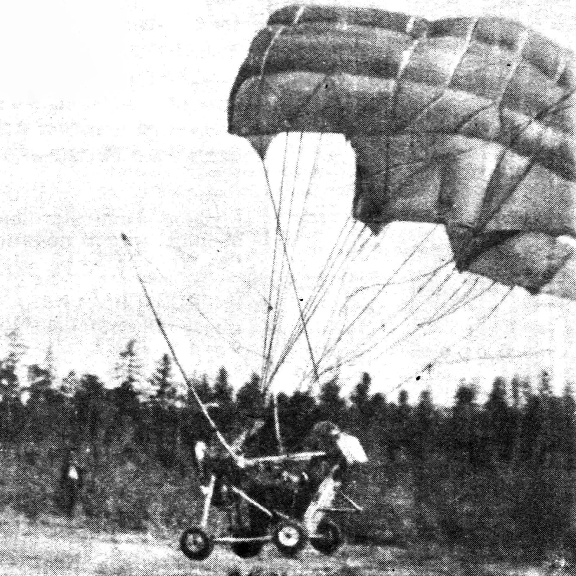
This powered paraglider (such craft are now more often called paramotors), developed at the design bureau of the “Eureka” amateur technical creativity club in the village of Torga, Yakutia, was named “Carlson-4”. The number in its name clearly indicates that this is the fourth variant of such an aircraft. Since 1985 we have accumulated considerable experience—primarily in towed flights with our designs.
The first thing we established was that using production parachutes as a wing for a paramotor is inefficient. So we had to develop a soft wing of our own design.
Preliminary calculations and numerous experiments showed that we needed an aircraft capable of hovering in place and taking off almost vertically. The optimal wing loading of the paraglider should be about 4.6 kg per 1 m², powerplant output 80 hp, and static propeller thrust about 240 kgf. Our “Carlson” was an attempt to approach these ideal parameters.
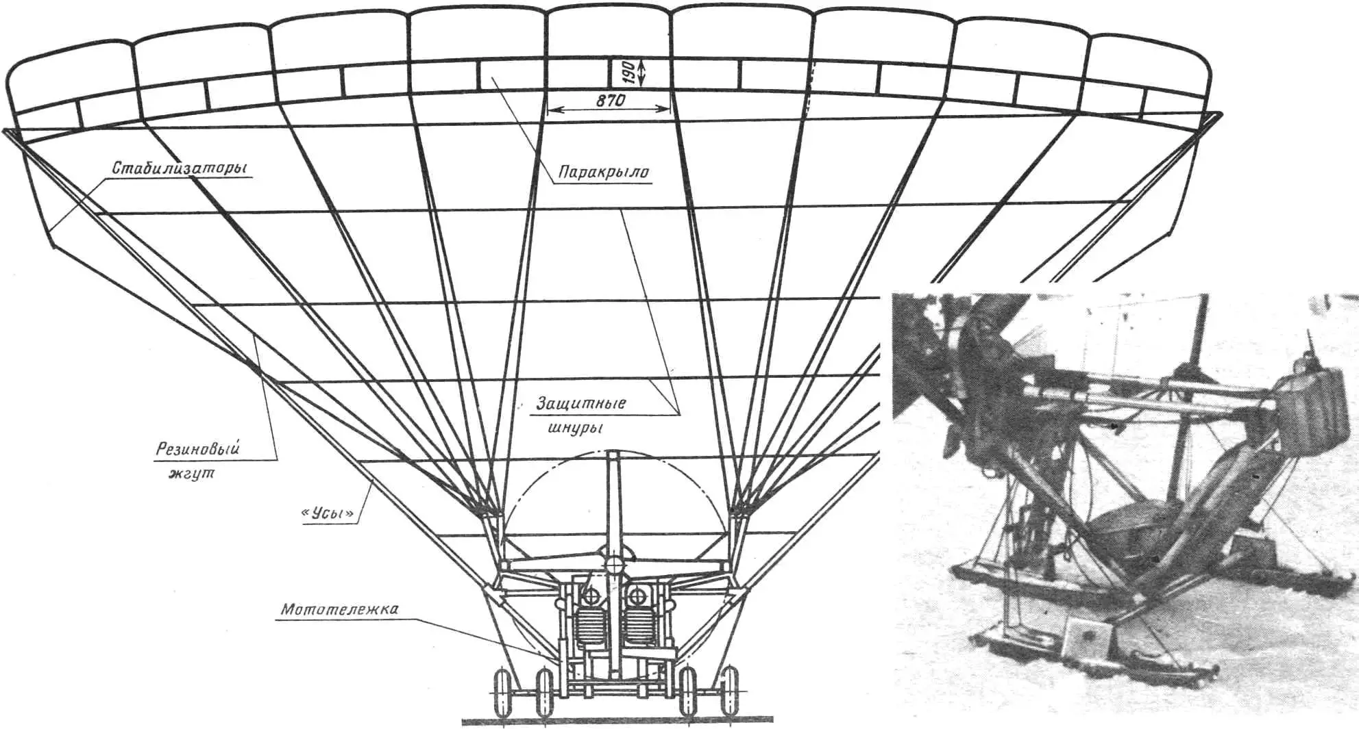
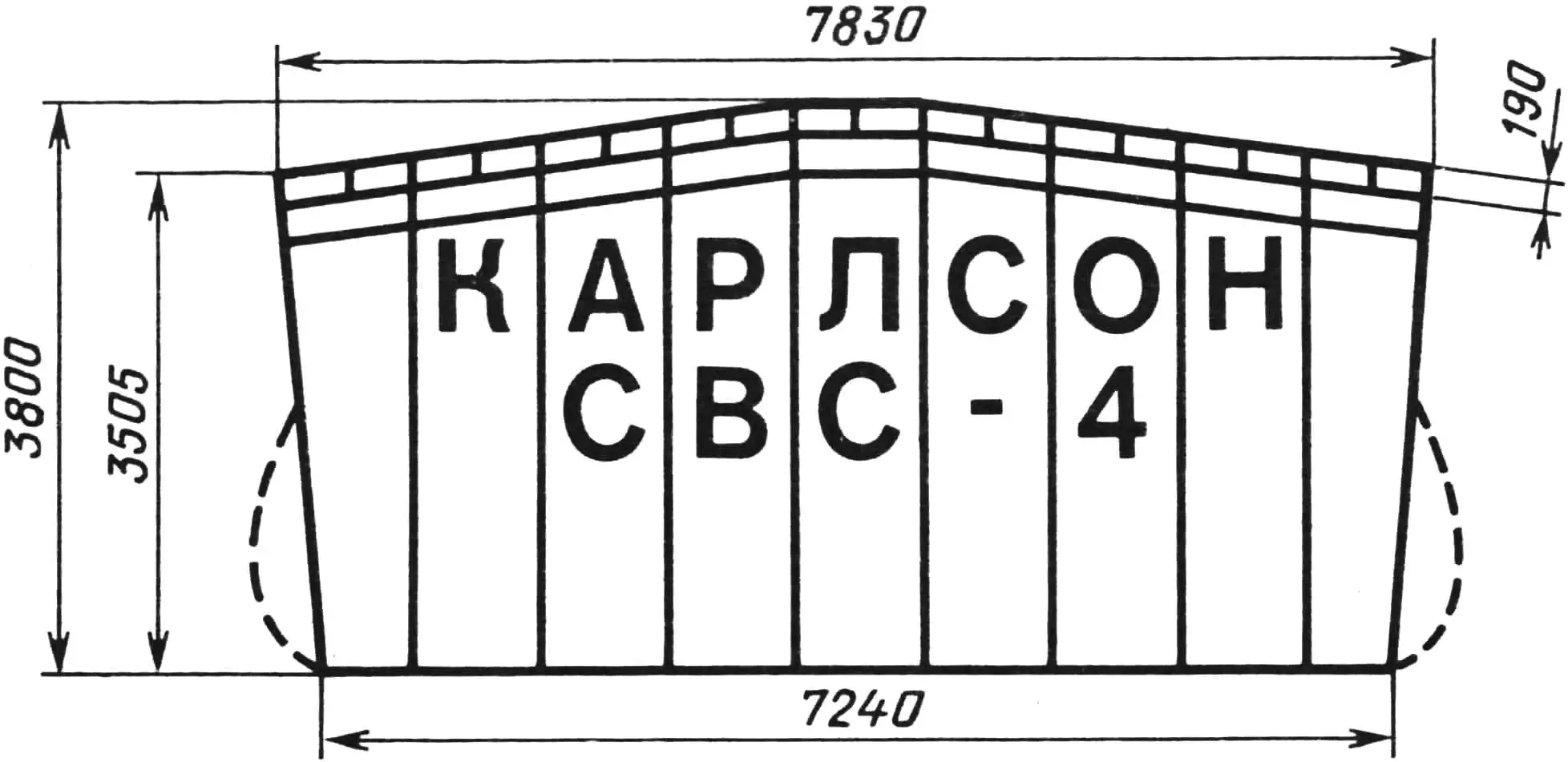
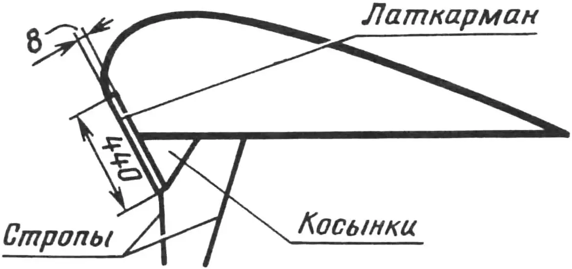
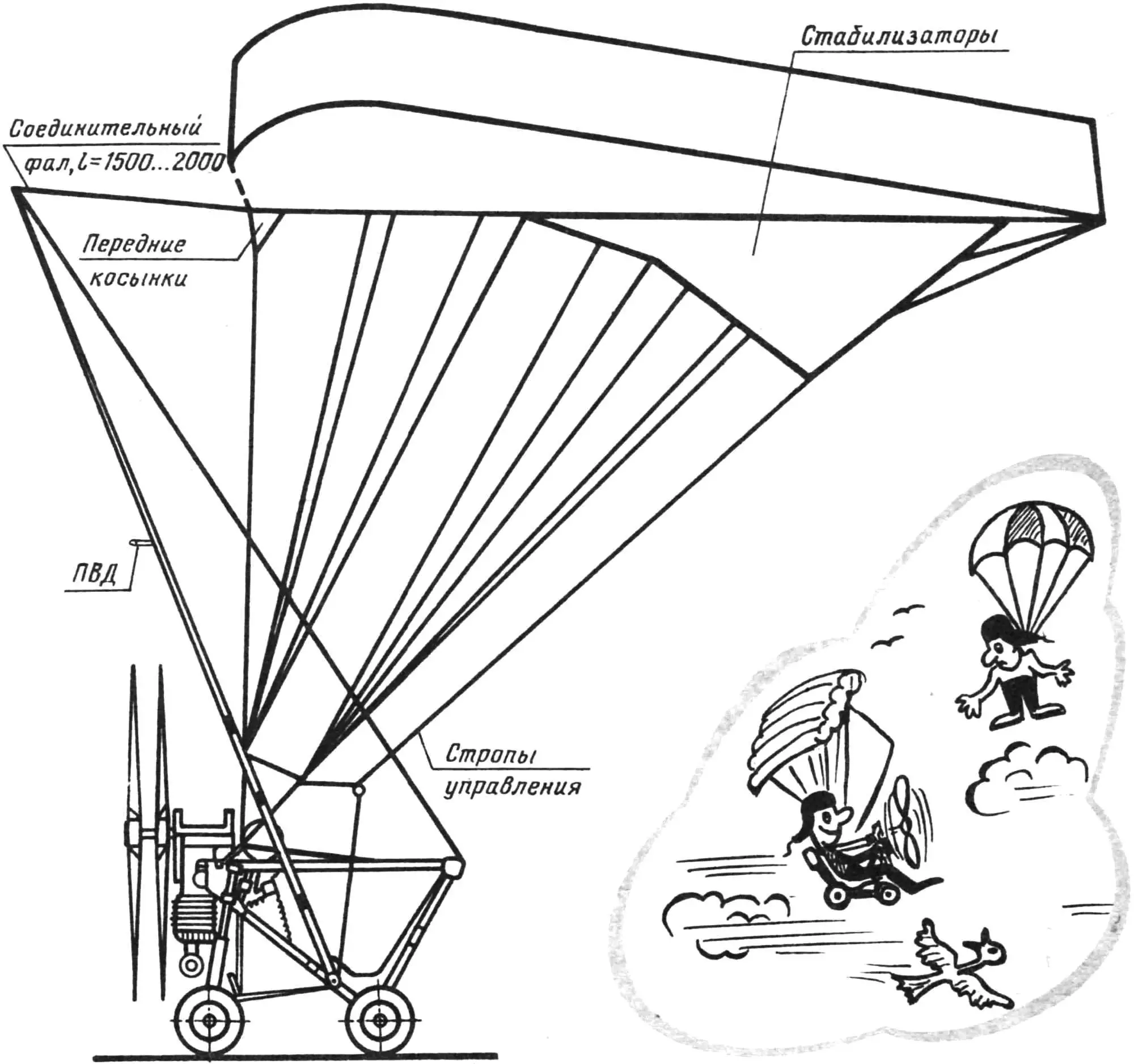
The parachute wing (parawing) of our aircraft is an elongated pentagon with an area of 31 m²; it consists of nine tubes 870 mm wide, each in turn divided by a rib into two sections. Tube air intakes are 190 mm high. This design provides relatively low parawing drag and fairly high aerodynamic efficiency.
The upper panel is cut from anorak-type raincoat fabric (Czech), although domestic “bolonja” raincoat fabric (art. 52087 or 52188) could also be used—the kind most production paragliders are sewn from. The lower panel is of dyed calandered fabric (art. 56005 KrPk or 56005 KrP). The same material is used for the front gussets, side ribs and stabilising panels. Main ribs are cut from nylon fabric (art. 56011 AP). The upper panel, ribs, stabilisers and gussets are reinforced with tapes (art. LTKP-15-185) forming a kind of load-bearing frame. Less loaded areas are reinforced with art. LTKP-13-70 tapes.
It should be noted that a powered paraglider wing does not experience in flight the loads that normally occur during parachute deployment. This means that, made to the pattern of a standard parachute, it will be inherently strong.
The parawing profile is quite thick—maximum height is 500 mm. In the front part of the ribs forming the air intakes, ten batten pockets 8 mm wide are sewn, into which bamboo battens (slats from Korean blinds) are inserted to prevent the intakes from “collapsing”, which promotes rapid wing inflation and increased stiffness.
Lines (60 pcs.) are made of thin cord ShKP-200 with 200 kgf strength. The two control lines are also made from it.
The harness is assembled from LTK-44-1600 tapes with OSK buckles (lighter OSK-D or KZU buckles may also be used). Free ends of the harness are of LTK-44-1600 tape, with four half-rings at the top and two buckles at the bottom. The rear free ends have rings for control lines used in towed flight. For powered flight the control lines are attached to the craft via extension lines. The free ends are joined at the top by a crosspiece.
The end parts of the parawing are fixed by two ShKP-200 cord lines to the upper parts of the “whiskers”. The latter, incidentally, perform more than ten functions on our paramotor, and their presence on this type of aircraft is well justified. These elements are made from duralumin tubes—we used sports javelins in particular, joining several blanks with adapter sleeves to the structurally required length—5100 mm. They are attached to the paramotor’s power cart at four points using textolite and steel adapters. Installing and removing the “whiskers” takes only a few minutes.
It seems worth mentioning that a scale radio-controlled flying model of the paramotor fitted with “whiskers” flew superbly, performing aerobatic figures including a Nesterov loop, all of it captured on film.
We found, in particular, that the “whiskers” guarantee preservation of the parawing’s working shape when the air intakes are open. Besides, the “whiskers” prevent the parawing from entering the propeller rotation zone, since cords in the form of a net are stretched between them. The “whiskers” prevent line twist, prevent the wing from folding in cross section, and improve safety in the event of a nose-over during take-off or landing run because they automatically set the parawing’s optimum angle of attack. Finally, the “whiskers” allow take-off without assistants: you only need to add throttle—and the parawing canopy is above your head.
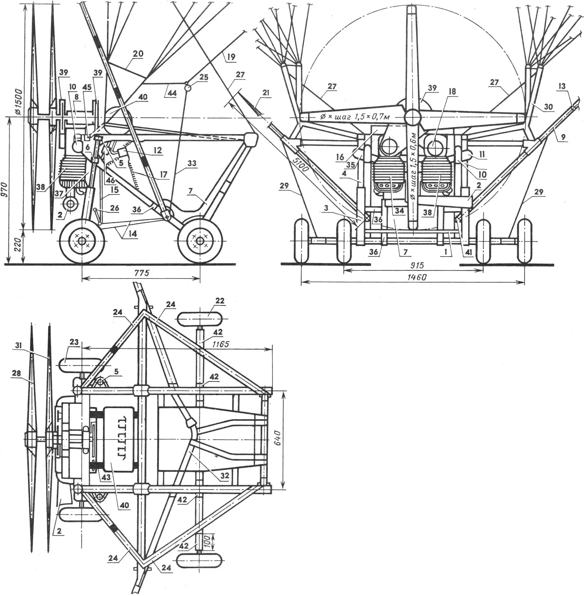
1 — transverse steering linkage, 2 — muffler, 3 — sliding tube of steering fork, 4 — fixed tube (“fork leg”), 5 — upper bridge of “leg”, 6 — lower bridge of “leg”, 7 — pilot seat, 8 — coaxial reducer, 9, 21 — “whiskers”, 10 — engine carburettor, 11, 35 — air filters, 12 — instrument panel, 13 — pitot receiver, 14 — cable drive to control pedals, 15 — front wheel control pedals, 16 — rectangular load-bearing frame, 17 — instrument panel suspension springs, 18 — ignition system generator, 19 — control lines, 20 — free-end crosspiece, 22 — rear wheel, 23 — front wheel, 24 — harness, 25 — control line toggles, 26 — carburettor throttle lever, 27 — rubber straps, 28 — front propeller, 29 — parachute rubber shock absorbers, 30 — free ends, 31 — rear propeller, 32 — safety belts, 33 — connecting cord, 34, 38 — IZH-Planeta-Sport type engines, 36 — seat load straps, 37 — cooling system ejector, 39 — cowling, 40 — fuel tank, 41 — “whisker” attachment joints, 42 — joints, 43 — fuel tank rubber shock absorbers, 44 — tape with ring (for removing toggles), 45 — harness front-end attachment bracket, 46 — ignition system KET.
The paramotor’s power cart is a space-frame structure assembled mainly from duralumin (D16T) tubes 40 mm in diameter, joined with 2 mm duralumin plates and textolite adapters. The rectangular load-bearing frame—for its manufacture we used a wing spar from a written-off An-2 aircraft.
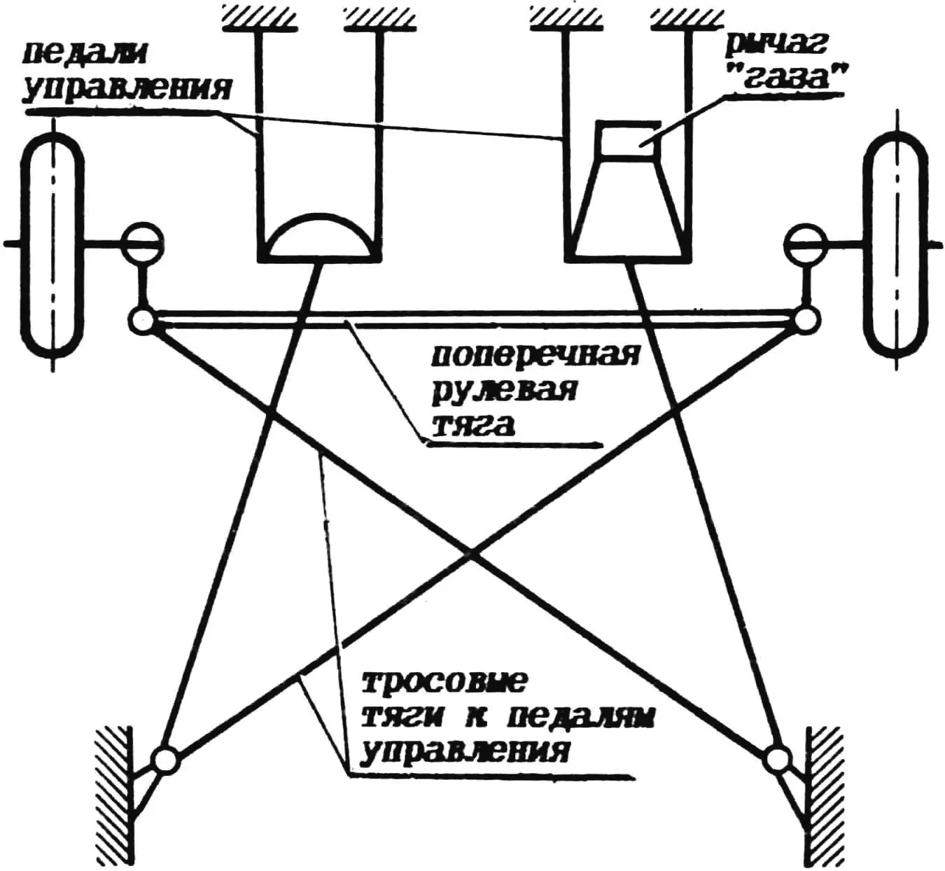
The power cart undercarriage is four-wheel, with two steerable front wheels. This layout has greater stability than a three-wheel one, and this advantage is especially evident on landings in crosswind—with sideslip. Three-wheelers in such conditions usually nose over, flipping over the front and one of the side wheels.
Each front wheel has independent suspension based on a motorcycle damper—a telescopic fork leg from the front fork of an IZH-15K motorcycle (similar units from an IZH-Planeta-Sport motorcycle can also be used). The legs are installed (each separately) in their upper and lower bridge, fixed at the front of the power cart on the spar with steel brackets. When mounting the legs, damper travel must be taken into account—when fully compressed there must be a safe clearance from propeller tips to the ground (at least 200 mm).
The front wheel steering knuckles are connected by a transverse link (D16T tube 28 mm diameter), forming a steering trapezium. Front wheel steering is by pedals connected by cable linkage to the front wheel steering knuckles. The undercarriage rear wheels are easily removable, which is convenient for transporting the paramotor.
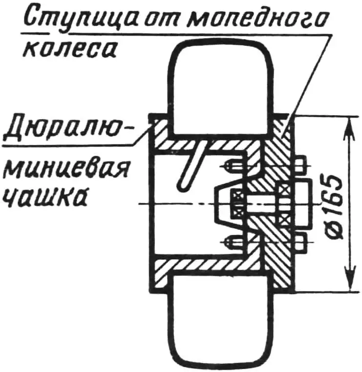
The undercarriage wheels are designed around hubs from a “Riga” moped, turned down for lightness. Tyres are 300×125 type, with lightweight casings and tubes from children’s bicycle tyres. Tyres are fixed to the hub with duralumin discs. Bearings are the same as in the stock hubs—No. 201. The undercarriage proved surprisingly robust—over three years of paramotor operation even the hardest landings did not put it out of action. Wheel hubs are secured with nuts and must be cottered.
The paramotor’s powerplant is twin-engine: it is based on two IZH-15K type engines (engines from an IZH-Planeta-Sport motorcycle can also be used—practically the same). The engines are heavily lightened—their gearboxes are cut away and only the mounting bosses remain. The cylinders with heads are mounted on the power cart sideways to the airflow, so to improve cooling it is necessary to cut the bridges in the centre of the cylinder between the fins and drill holes in all head fin ribs. The modified engine (without ignition system, carburettor, mufflers and driven sprocket) weighs 18.5 kg, fully equipped—22 kg. Carburettors on our powerplant are Japanese “Mikuni” type, though the more readily available 43-350 would also suit. The muffler is home-made, welded from sheet steel—one for both engines. Ignition is contactless electronic, KET-1a type—as on the “Voskhod” motorcycle. Generator—G-427 (7 V, 60 W), ignition coils—B-50M. Plugs—A-23, their caps additionally secured with springs.
The engines were not modified for higher output. Light air filters are fitted on the carburettors—mainly to create intake resistance, which somewhat improves throttle response. Fuel reaches the carburettors by gravity (in principle, an outboard motor pump could be used).
Carburettor throttle control is foot-operated: the throttle sector is on one of the control pedals (on our paramotor—the right one). Remote engine “stop” buttons are on the right and left parawing control toggles. Ejectors of thin sheet duralumin are fitted near each cylinder, substantially improving engine cooling.
Each engine is secured at five points through rigid rubber pads. The powerplant layout somewhat resembles that used on the “Poisk-5” motorglider (see No. 3, 1988), except that our paramotor uses chain drive. The reducer shaft must have a radial thrust bearing, since thrust creates significant axial load. The chain reducer drive sprocket has 19 teeth; it is welded to the ground-down helical drive gear from an IZH-Planeta-Sport engine. The driven sprocket has 42 teeth, taken from the rear wheel of the same motorcycle.
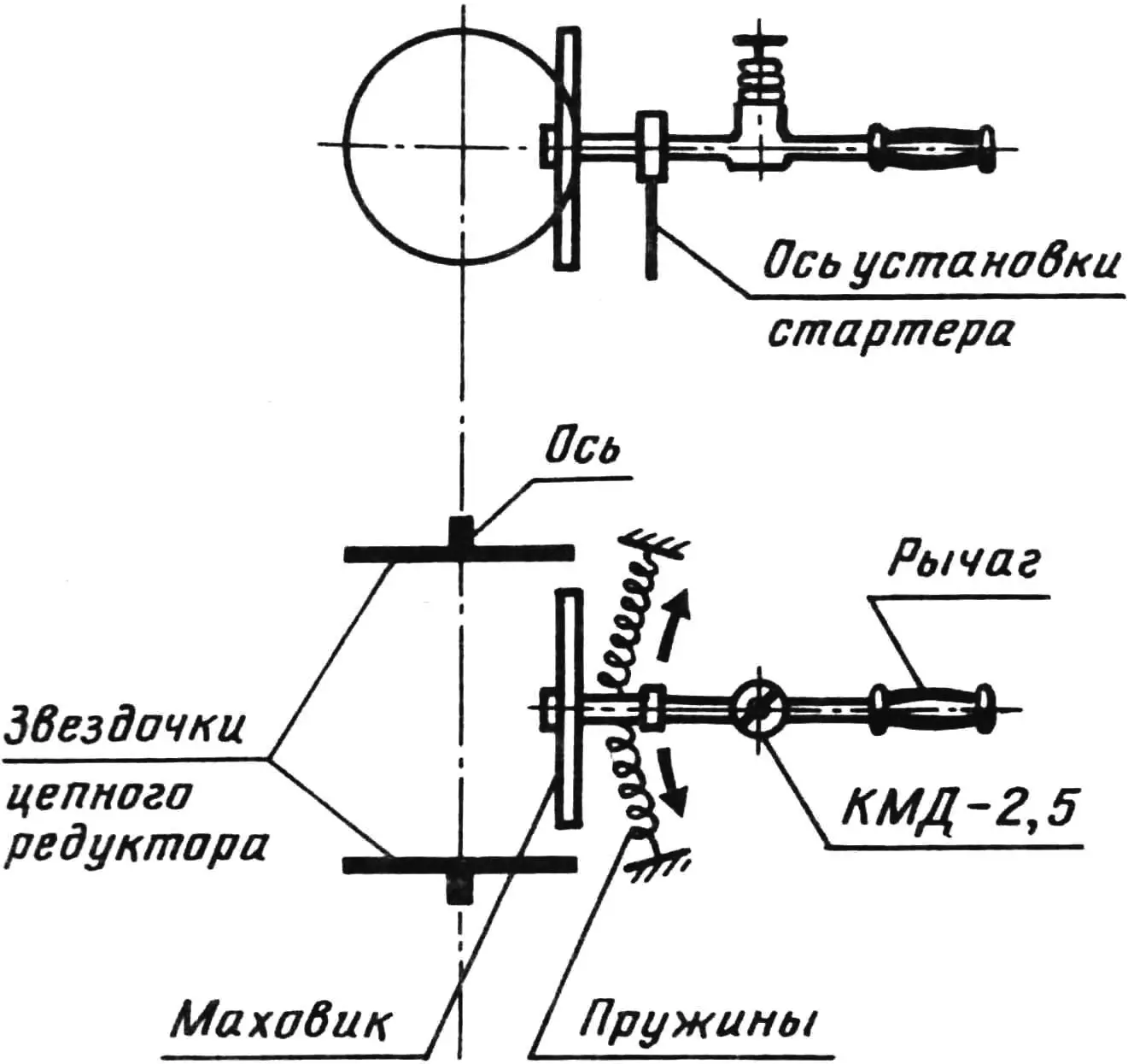
Engine starting is by an inertial starter we developed, based on the KMD-2.5 micro-engine. The mass of this device is only one and a half kilograms (mainly the flywheel). For the starter to work, a fuel mixture is required consisting of 31% ether, 45% kerosene, 8% castor oil and 16% MS-20 type oil. The KMD-2.5 starts easily (the flywheel need only be spun sharply by hand) and reaches 10…12 thousand rpm. Paramotor engine starting is done in turn using a friction attachment on the flywheel: it provides contact between the spinning flywheel and the secondary shafts of the chain reducers.
The powerplant has two propellers: the first—1500 mm diameter, 700 mm pitch; and the second—same diameter but 600 mm pitch. The reduction in pitch of the second propeller relative to the first allows for the twist imparted to the flow by the first. Both are made from a dry pine blank, epoxy-glued from four boards. After final machining their surfaces were covered with glass cloth in epoxy resin. On the central hub (flange) each propeller is fixed with bolts, nuts and washers, with mandatory nut locking by the method described in No. 12, 1988.
The fuel tank is transparent (from a ten-litre polyethylene can), placed in front of the pilot on rubber shock absorbers; fuel feeds to the carburettors by gravity. If a fuel pump is to be used, it makes sense to mount the tank at the rear.
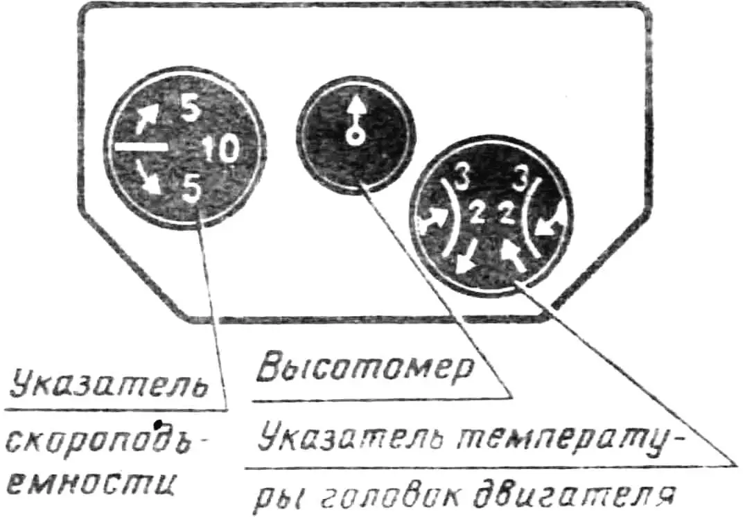
The instrument panel is spring-mounted—this protects it from vibration. Mounted on the panel are a variometer, altimeter and cylinder head temperature indicators (two TST-47). The pitot (PVD) is mounted on the “whiskers”.
The pilot seat is cut and sewn from avisent with foam padding. It is attached to the power cart with LTKkr P-813-800 type tapes and fitted with safety belts. Seat position can be adjusted for height depending on pilot stature. In cold weather an acrylic windscreen is fitted in front of the pilot.
When tuning the craft, particular attention should be paid to its trim. Approximate attachment points of the power cart to the wing are shown in the diagram. However, the position of the points is determined more precisely after trial flights to 2…3 metres altitude: the craft is oriented so that the “whiskers” do not tug on the parawing—otherwise the wing may shift to a negative angle of attack. Notably, paramotor trim is significantly affected by propeller thrust, since the power cart is suspended from the parawing at two points, and when the toggles are pulled the trim shifts relative to the wing focus. Nevertheless, a well-tuned parawing–power-cart system is sufficiently stable and quickly returns to stable equilibrium under any adverse disturbance.
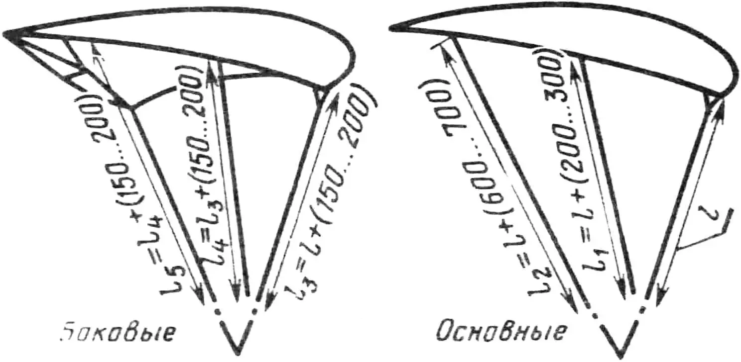
By adjusting line lengths the wing profile can be modified within certain limits. The wider the free ends are spread, the higher the paramotor’s lateral stability. And by adjusting the side stabilisers the parawing can be made stall-resistant and turn rate changed. When adjusting, it is recommended to increase the length of any given lines by no more than 50 mm, checking the effect of the change in trial flights to 1.5…2 m altitude. The lines of the two front rows of the parawing must be strictly equal: maximum length deviation—no more than 10 mm.
Adjustment of the first row centre line lengths starts from 2800 mm. When their length is reduced, the vertical component of glide speed increases, and already at 2500 mm length the side air intakes do not inflate. Side lines should be 200 mm longer than the main ones—lateral stability of the parachute system depends on this. Line lengths should be measured from the half-ring buckles to the parawing lower panel, including the length of stabilising panels and gussets. A correctly tuned wing in glide has a negative angle of attack and is tilted with air intakes down. The difference in length between the first and last (sixth) row lines is 1250 mm.
In powered flight (with thrust) the parawing angle of attack is 7…10 degrees. On take-off and landing this angle is somewhat greater.
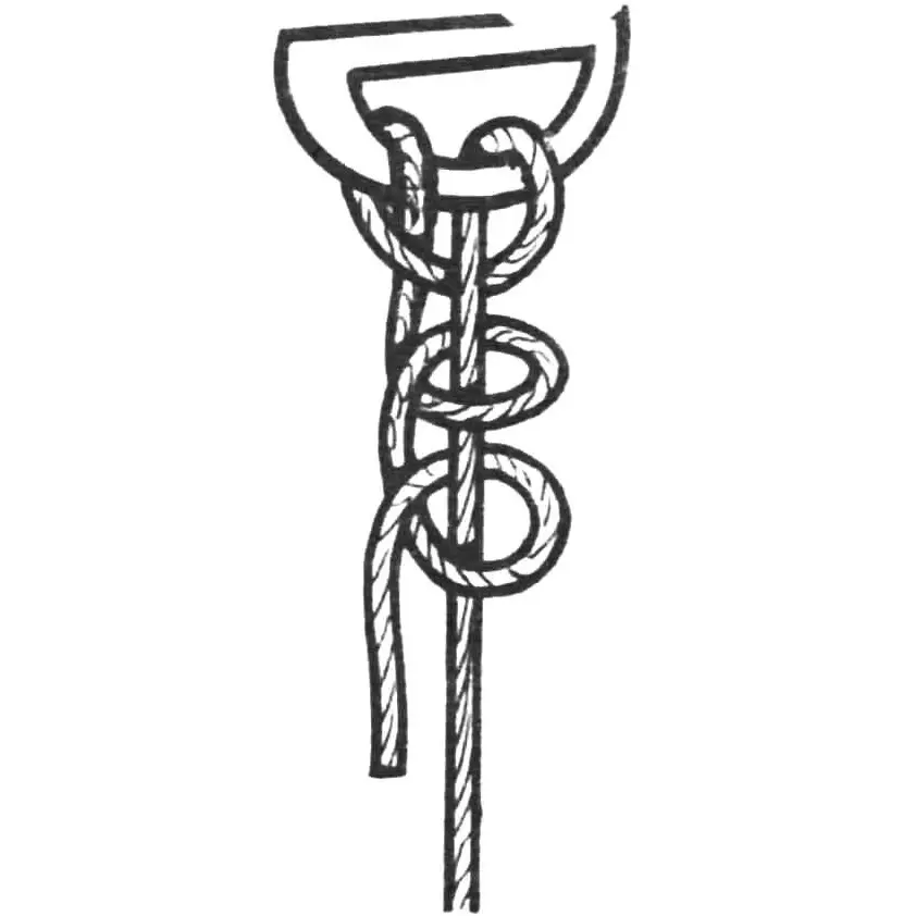
Line length adjustment is done by sequentially untying the line attachment knots on the half-ring buckles of the harness free ends. After the length is finalised, the knots on the lines are retied with a simple five-to-eight-turn “half hitch”, as shown in one of the figures. Later, when the line length is determined, its end is sewn with nylon thread No. 9–13, which fully prevents such a knot from coming undone.
When making trial flights it should be borne in mind that pitch control (up or down) is by engine rpm, and turning by pulling the appropriate control toggle.
MAIN TECHNICAL SPECIFICATIONS OF PARAMOTOR «CARLSON-4»
Mass, kg
— parawing … 7
— power cart with equipment … 36
— powerplant … 52
— craft with parawing … 95
— useful load … 80
— take-off … 185
Parawing parameters
— span, mm … 7830
— chord, mm … 3760
— area, m² … 31
— sweep, deg … 5
— aspect ratio … 3.76
Powerplant parameters
— engine power, hp … 2×32
— max. rotational speed, rpm … 6500
— static thrust, kgf … 160
— propeller diameters, m … 1.5
— propeller 1 pitch, m … 0.7
— propeller 2 pitch, m … 0.6
— propeller 1 speed, rpm … 2750
— propeller 2 speed, rpm … 2850
— power loading, kg/hp … 2.89
— fuel consumption, l/h … 14
«MODELIST-KONSTRUKTOR» No. 2’95, Yevgeny SHABUROV, Torga (Yakutia)
Recommend to read
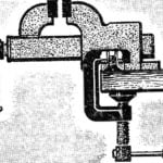 CLAMP AND VISE
There just clips and the clips do not come up with designers - and all this only in order to securely attach bench vise on the workbench. Not everyone, however, can be used in a home...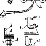 NEW FROM OLD
In the mixer tap in the bathroom sometimes breaks the pin on the shower switch cold-hot water. In the store it is almost impossible to find, and a new faucet is expensive. It is fixable....
