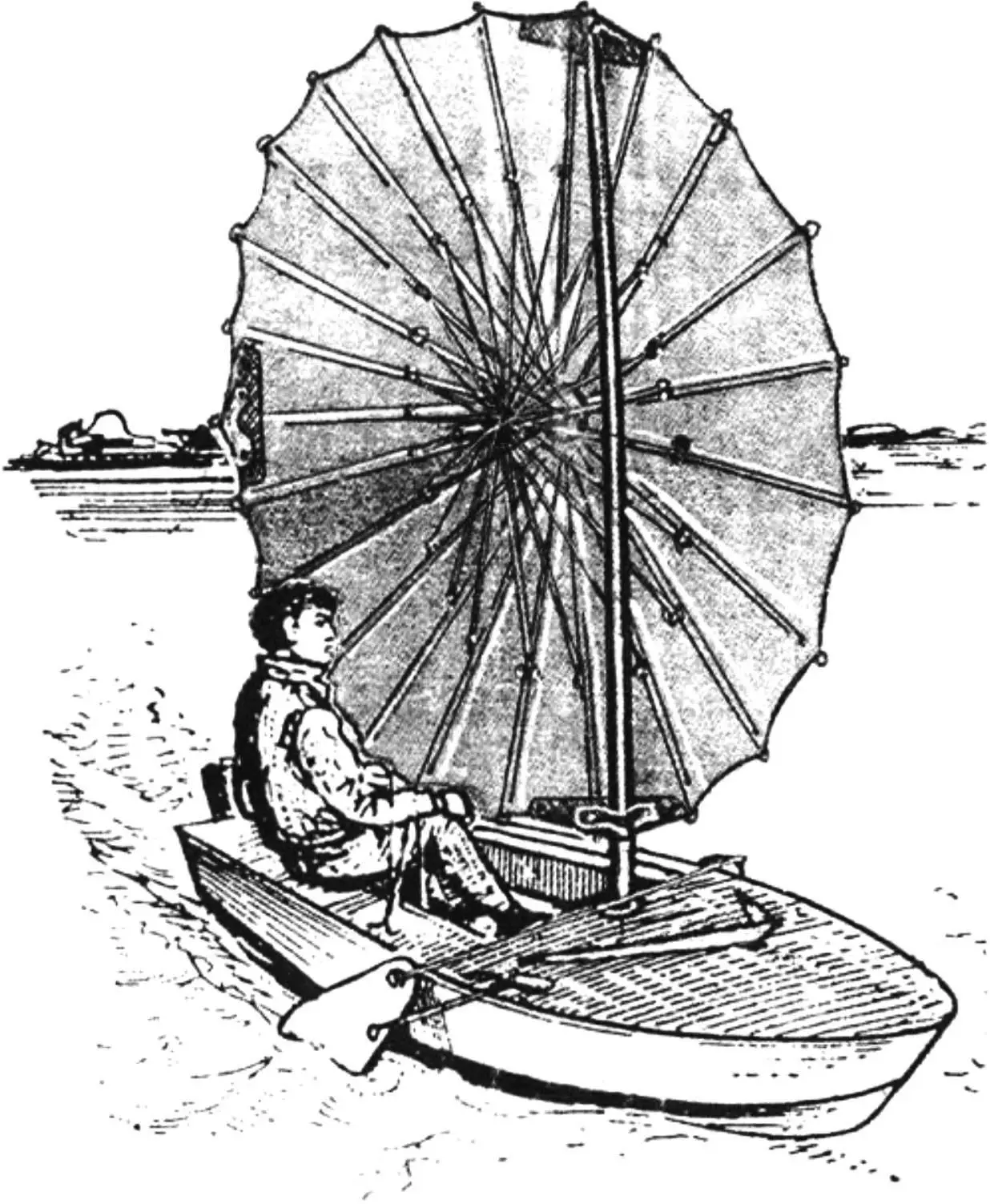
It seems that the idea of using an umbrella as a sail has occurred to everyone who has ever opened one in a strong wind. However, the first person whose attempt to use an umbrella instead of a sail was recorded at the time in the magazine “Modelist-Konstruktor” was Georgy Arbuzov, one of the pioneers of windsurfing in our country and chairman of the windsurfing section under the FPS of the USSR.
In the mid-1970s he built his own sailboard, but there was no opportunity to test it on the water — the spars were not yet ready. Then Georgy used a large umbrella instead of a sail, and it turned out that a windsurfer with this improvised propulsor showed quite good sailing qualities. At that time, however, the idea of a rigid round sail was not developed further — only classic windsurfers were admitted to competitions.
Meanwhile, many years later Arbuzov’s idea was nevertheless implemented on a compact centerboard dinghy (or, more precisely, an umbrella boat) of simplified design. A beach umbrella 2 m in diameter — and thus with an area of 3.14 m2 — was used as its sail.
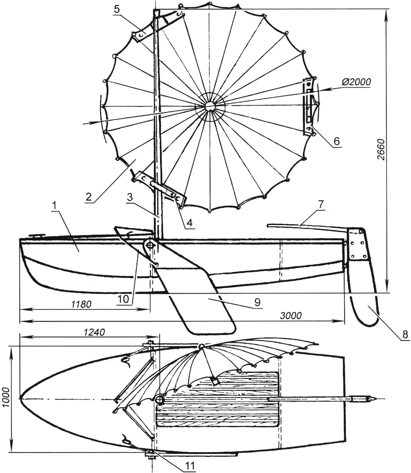
1 — umbrella-boat hull; 2 — umbrella sail (beach umbrella Ø2 m); 3 — mast (pine, 50×50 bar), 4,6 — lower umbrella-sail attachment fittings; 5 — upper umbrella-sail attachment fitting; 7 — tiller of the rudder gear (beech or oak, 30×30 bar); 8 — rudder blade (plywood s12); 9 — leeboard (plywood s12); 10 — stop line; 11 — crosspiece for mounting the leeboards (duralumin, tube Ø22×2)
The boat’s hull is wooden, with a frame consisting of three frames (bulkheads), a keel, a pair of beams, and four stringers.
The frames are assembled from pine battens of 25×60 mm cross-section using half-lap joints; on frame 1 the joints of the battens are reinforced on both sides with plywood knees 3–4 mm thick, while on frames 2 and 3 they are reinforced with a continuous plywood sheathing of the same thickness.
The frames are assembled on a chipboard sheet with a lofting plan glued to it — a sheet of drafting paper with the outlines of these structural members drawn on it, over which a polyethylene film is stretched to prevent the wooden parts from sticking to the paper. After all parts (knees and sheathing) have been fitted to one another, the frame is assembled using epoxy glue and self-tapping screws. It is advisable to use fasteners with a protective coating — cadmium-plated or galvanized.
The hull frame is assembled on a flat floor — for example, on a chipboard sheet of suitable size. First, the trace of the hull’s plane of symmetry and the locations of the frames are marked on it; then, using wooden braces and screws, the frames are set up on the improvised building stock with the keel side upward.
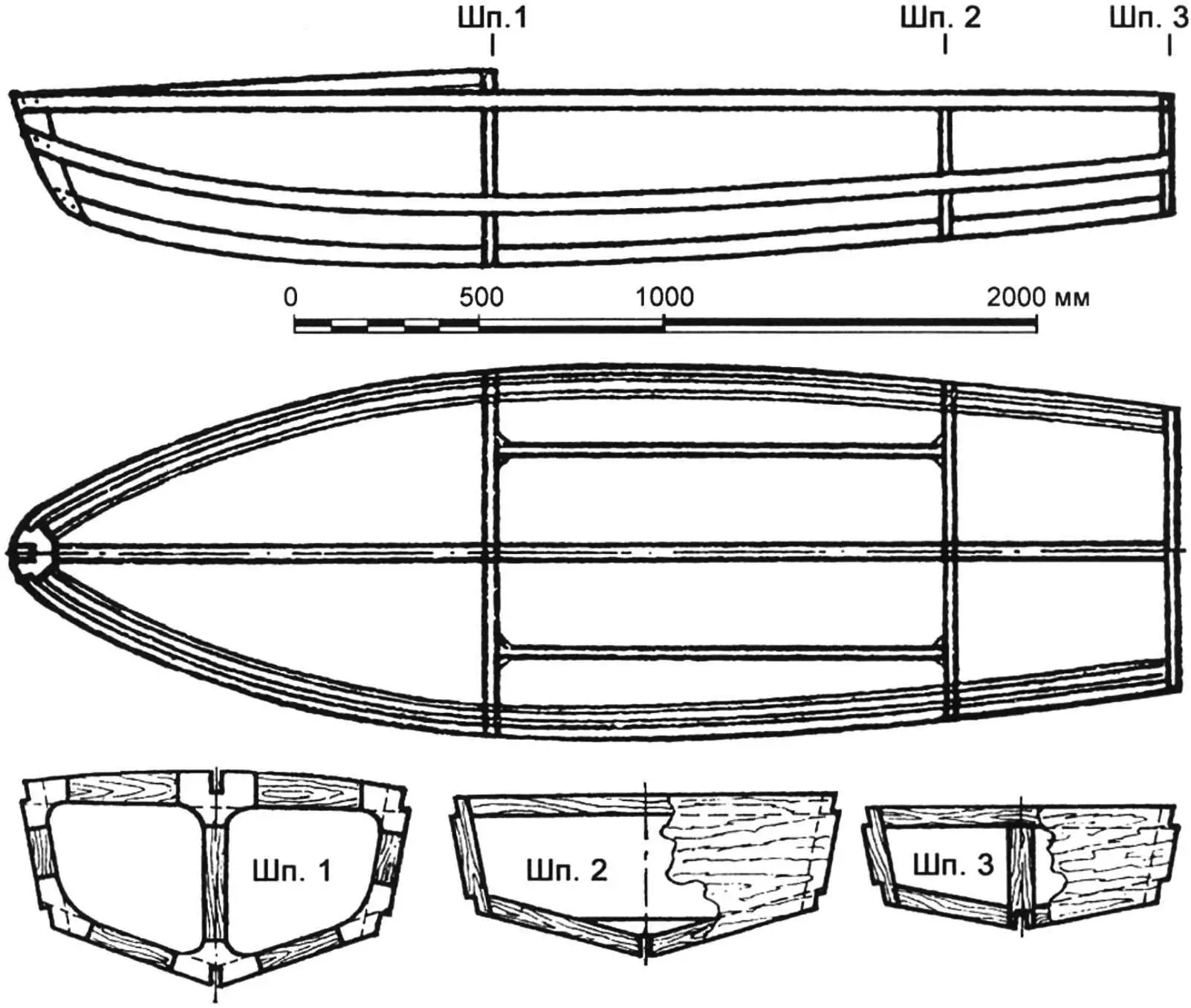
First, using epoxy glue and self-tapping screws, the keel timber is secured; it consists of two parts — the keel timber itself and the stem. The stringers and beams are best fitted and temporarily fixed on the frames in pairs — first the upper ones, then the lower ones, and finally the beams. Their final attachment to the frames with glue and screws is also done in pairs, with careful checking of the frame’s symmetry after each operation.
After the glue has cured, the frame is faired with a plane, a rasp, and sandpaper glued to plywood strips. The umbrella boat’s planking is plywood. It should be noted that a standard plywood sheet is substantially shorter than three meters, so the blanks will first have to be scarfed “on the bevel” over a length of about 50–60 mm and fixed with the same epoxy glue. To avoid errors when calculating the shape of the planking parts, it makes sense to make cardboard templates first; only after a series of fittings and try-ons can the outlines of the planking elements be transferred to the plywood blanks.
The frame should be planked with pairs of symmetrical parts — the starboard and port sides at the same time, then the starboard and port bottom sheets, constantly checking the symmetry of the hull. The plywood blanks are fastened with epoxy glue and self-tapping screws.
In the upper part of frame 1, a duralumin tube with an outside diameter of 22 mm is secured with screws and epoxy putty; it is intended for mounting the side leeboards on it.
The umbrella boat’s deck is made of 4-mm plywood and is attached to the frame members with epoxy glue and self-tapping screws.
After the hull has been assembled, the joints between the planking sheets are filled with epoxy putty; then, after it has cured, the entire outer surface is sanded. From the inside, the joints of the planking with the frame members are filled with epoxy putty, after which the hull is coated with two or three layers of parquet varnish and painted with automotive enamel.
Two necks from plastic bottles are glued into the transom board at the bottom level — through them, water that gets into the hull will be drained. The lower part of the cockpit is covered with two floorboards (sole gratings) — lattices made of wooden battens of 20×80 mm cross-section, coated with two layers of parquet varnish.
The leeboards and the rudder blade are cut from 12-mm plywood. Their profile is symmetrical — rounded at the leading edge and pointed at the trailing edge. After machining and final sanding, the plywood parts are coated with several layers of parquet varnish and then, after sanding, with bright automotive enamel.
The pivot axis of a leeboard is a steel stud with an M14 thread on one of its ends; the leeboard is secured on it between two nuts and two washers. The leeboards are held on the boat with a rubber shock-cord with a pair of hooks at its ends. To keep the leeboards from floating up underway, they are hauled down with a pair of lines to cleats mounted on the deck.
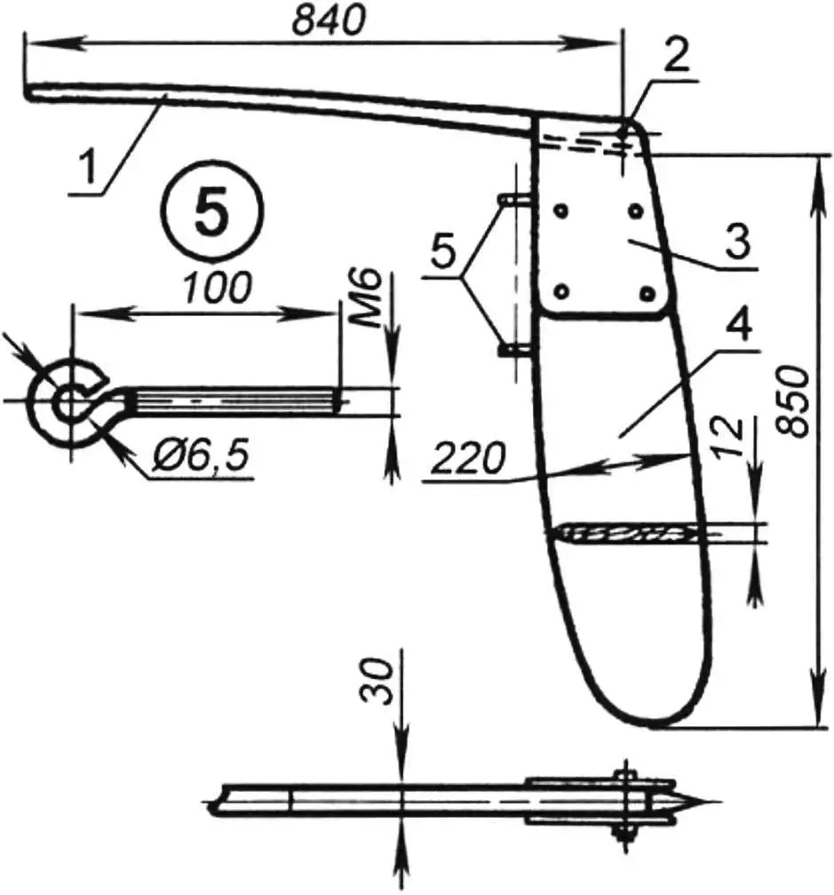
1 — tiller (beech or oak, 30×30 bar); 2 — tiller hinge (bolt with nut); 3 — cheek (duralumin, s2.5); 4 — rudder blade (plywood s12); 5 — hanging pintles (steel, Ø6 rod)
The rudder blade is attached to the dinghy’s transom with the simplest pintles — each consisting of a bracket bent from 6-mm steel rod into an L shape, and a mating part from the same rod resembling a safety pin with a ring. The pintles are secured with epoxy glue in holes in the transom and in the forward part of the blade. The tiller is made from an oak or beech batten and is connected to the rudder blade by a hinge.
The umbrella boat’s mast is rotating and made of pine; its length is 2600 mm, the diameter at the top is 30 mm, and at the bottom 50 mm. If the mast’s strength proves insufficient, it makes sense to wrap it with two layers of fiberglass cloth using epoxy resin. The mast supports on the umbrella boat are a step (a steel socket with an inside diameter of 50 mm) installed on the hull keel, and a clamp made of steel strip fastened to frame 1. Accordingly, a heel — a metal or plastic cap with an outside diameter of 48 mm — is fitted at the lower end of the mast, and a steel band about 50 mm wide is fitted in the area of the upper mast-support clamp.
As mentioned above, a beach umbrella 2 m in diameter is used as the sail on the little craft; it can be bought in a sports shop where camping gear is sold, or ordered online.
The long pole so necessary for a beach umbrella is not needed for the sail — it must be cut flush with the end of the sleeve that slides along the pole when the umbrella is fully opened.
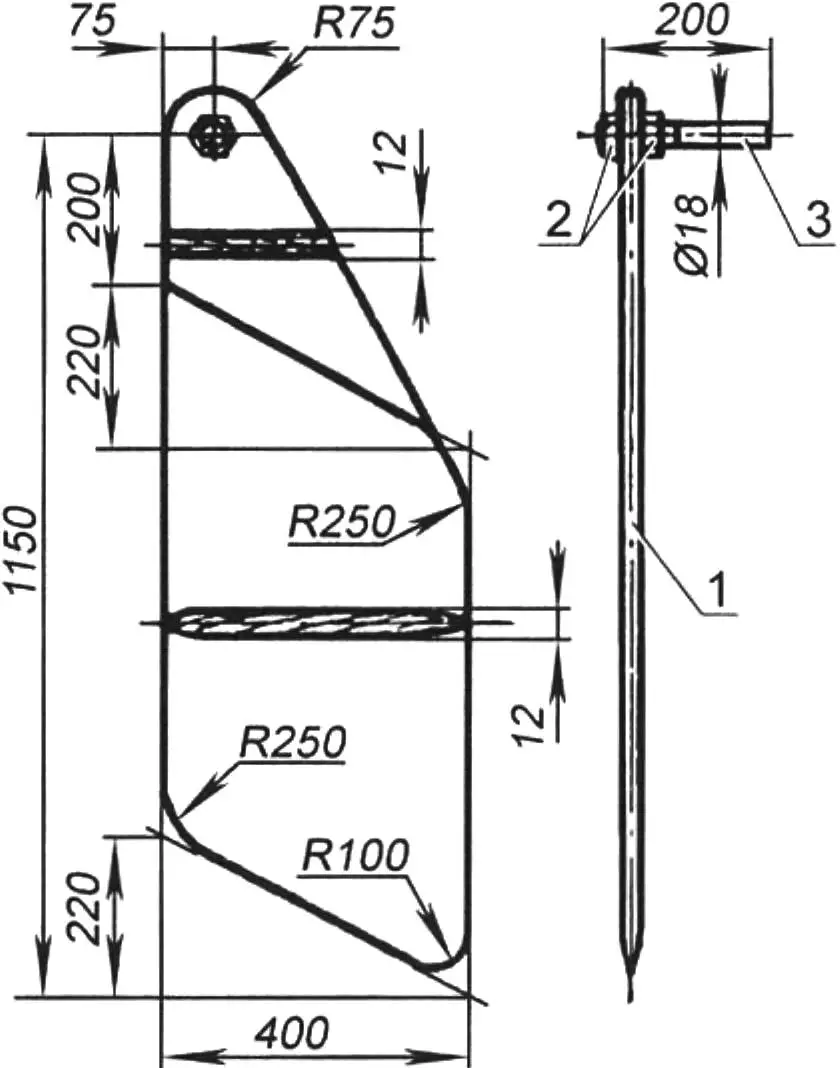
1 — leeboard (plywood s12); 2 — M14 nuts; 3 — leeboard bushing (duralumin, tube 18×2)
The umbrella sail itself has three fittings for attaching it to the mast. The upper (hinged) fitting, on which it is hung from the mast, allows the position of the umbrella sail relative to the mast to be changed when tacking. It consists of a pair of duralumin plates fastened to two (or three) umbrella ribs with several M5 screws and nuts, and a U-shaped loop of 6-mm steel rod with an M6 thread cut on its ends. The mating part of the fitting — a hook bent into an L shape with an M6 thread cut on its “leg” — is fastened to the mast. Each of the lower fittings also consists of a pair of duralumin plates and a latch that holds the umbrella on the mast when tacking. It should be noted that the lower fittings are also used to attach the sheet — a synthetic or linen rope about 12 mm in diameter.
When tuning the umbrella boat, the main thing is to align the center of effort (CE) of the sail with the center of lateral resistance (CLR) of the hull. It should be borne in mind that the CE of the umbrella canopy is located about 0.5 m from its leading edge. As for the hull’s CLR, it will have to be determined experimentally. To do this, the sailboat is fitted with leeboards and a rudder blade and launched; roughly in the leeboard area, a line is tied to the side of the hull. If you pull the line perpendicular to the boat’s centerline plane and the craft then moves parallel to its longitudinal axis, the point where the line is tied is the center of lateral resistance. Most likely, however, when the line is tensioned the hull will start to turn, and in that case the attachment point of the line will have to be shifted and the experiment repeated until the hull begins to move parallel to the longitudinal axis.
If it then turns out that the CE and the hull’s CLR do not coincide, the CLR position can be corrected by angling the leeboards forward or aft. The CE position can be changed by raking the mast.
A well-tuned sailboat should have a slight tendency to round up (point higher into the wind), which helps in sudden gusts to bring the craft into the head-to-wind position — bows to the wind.
“Modelist-Konstruktor” No. 7’2012, I. MNYOVNIK
Recommend to read
 HUMMER H2
The first production models of this vehicle was delivered to army units in September 1985. The machine incorporates the most advanced technical and technological solutions of its time... HOW TO MAKE “ZIMMERIT”
Anyone interested in the history of armored vehicles is well known that highly characteristic feature of the external appearance of the German tanks since 1943 was an anti-magnetic...
