BOXER – OUT OF COMPETITION!

BOXER - OUT OF COMPETITION!
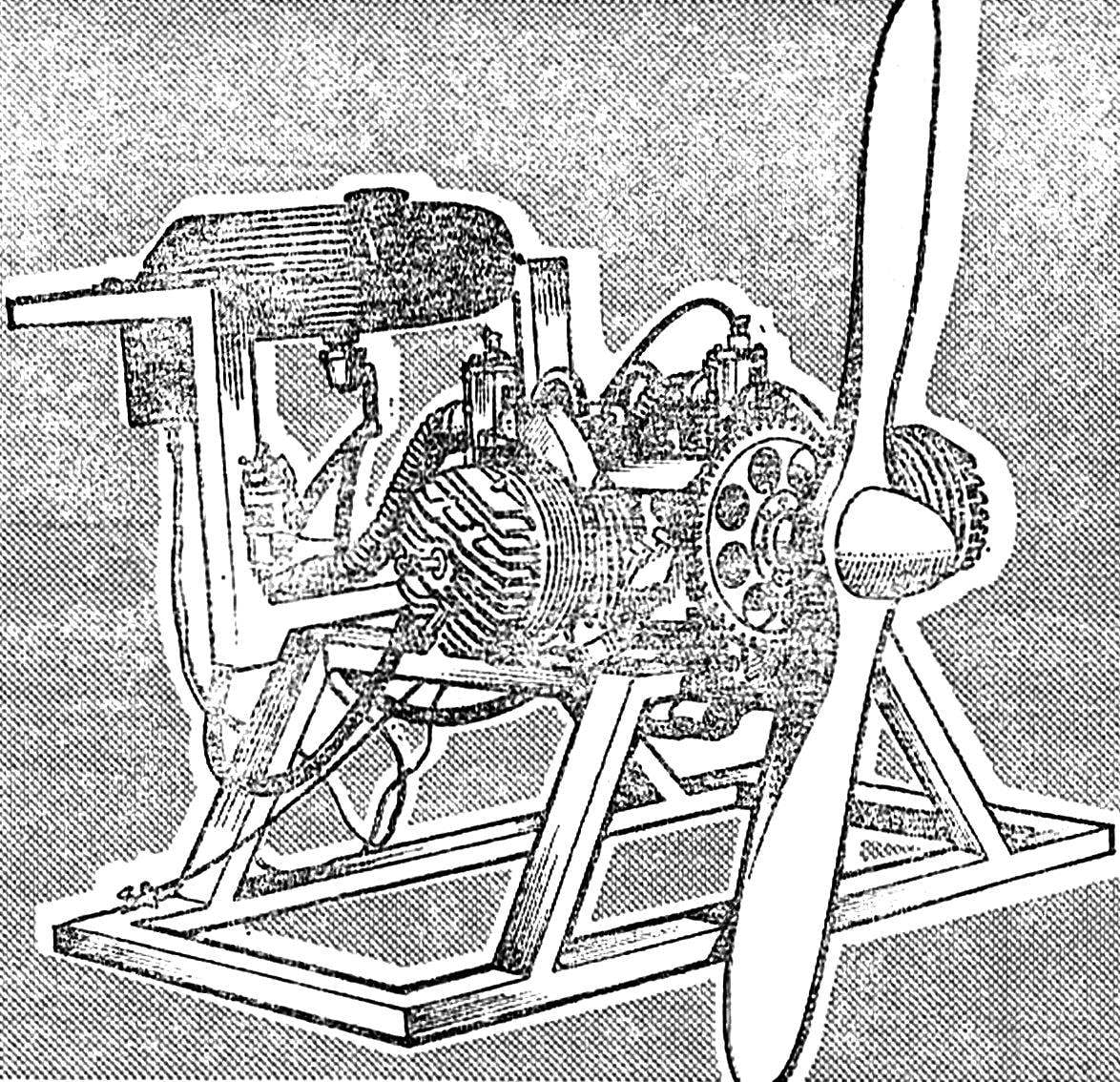
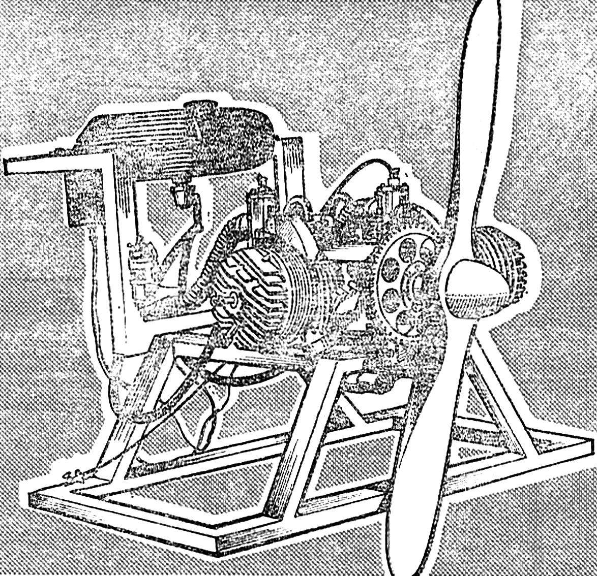
This two-cylinder engine, which received the name DD-700/40, designed and built the head of the public design Bureau “Aerocam” George Dorfman. The motor turned very good: reliable, relatively simple, easy enough.
The engine was exhibited at the IV all-Union review-competition, the SLA-87, was spiced up by the technical Committee of the rally.
 
To date, we have built several instances of such engines, and they all showed almost the same characteristics and high reliability. Now “Aerosol” is designing a power plant with a collapsible crankshaft and Zolotnik induction system. In addition, built boxer four-cylinder engine with a capacity of about a hundred horsepower.
 
When designing the engine DD-700/40 we tried to simplify the structure of its components, to achieve high reliability in operation. To fulfill the first condition was based on the use of series parts, motors, and homemade provided for the application of advanced technological methods.
As the title of the motor, its working volume — 700 cm3, power — 40 HP by the Way, the latter characteristic is obtained not only by calculation, but for bench testing, the engine speed in this case was…5100 5600 min-1. The weight of the engine without propeller, electric starter, gear wreath and the electronic ignition is only 30 kg — that is less than one kilogram per horsepower.
 
Crankshaft. The cheeks of the crankshaft is of steel 30KHGSA. First on the lathe handled three identical blanks — their diameter is 140mm, thickness is 23.5 mm. the resulting “pancakes” hardened to HRC 33…38, after which they are sanded to a thickness of 23 mm.
 
The holes in the cheeks and 25Н7 Ø Ø 35Н7 chiseled on a jig boring machine. At the same time to achieve should be minimum deviations in the tolerances in the direction of increasing diameter.
 
Axle crankshaft — steel 40ХНВА. Raw stock machined with an allowance for the diameter of 0.5…0.7 mm, the cylindrical zone Ø 40 mm and cone — with an allowance of 1.5 mm. the workpieces are milled keyways and drilled the safety hole, then these details thermoablative up to HRC 48…54. Note that less hardness of axles, the seals quickly “eat” the shaft. Hardened work pieces are processed in the installation blasting, then polished cylindrical sections with diameters 35И8, 43, 18 and 12 mm of Thread should be cut into resubstitution the machine.
 
The lower connecting rod fingers of steel SHKH15. The workpiece should be termoobrabotki up to HRC 62…65.
 
The Assembly of the crankshaft — the operation is very responsible. It begins with the fact that the lower connecting rod fingers deeply cooled in liquid nitrogen and using a screw or hydraulic press is pressed into the middle of the cheek of the crankshaft.
 
Fig. 1. The unit
Fig. 1. The unit “shaft-the Carter” two-cylinder boxer engine DD-700/40 (connecting rods conventionally not shown):
1 — a cranked shaft, 2 — bolt M6, 3 — washer 4 — front cover (steel 30KHGSA), 5 — front gasket (to put on bakelite varnish), 6 — Carter (D16T), 7 — back strip (to put on bakelite varnish), 8 — back cover (D16T), 9 — oil seal 40Х57Х10 mm (from the engine VAZ), 10 — M6 screws, 11 — bearing No. 2208, 12 — bearing No. 36208, 13 — ring 80X70X2 (steel 20), 14 — the bearing № 208.
 
Then one of the fingers going the connecting rod bearing and the connecting rod with the side washers. Below the rollers are not scattered, they are fixed in any way. Cheek with a rod is also cooled in liquid nitrogen, and in the middle hole, cheeks, inserted the tube; the groove should face toward the rod. Then the tube is put on the outer cheek, in this case will serve as a guide, on which when pressing begin to slide the outer cheek. So as not to crease the cheeks and do not bend connecting rod fingers, when pressing between the cheeks invested faceted spacers with a thickness of 19 mm.
 
The same operation is repeated for the second outer cheek of the crankshaft. Distracting first tube and inserted in the middle of the cheek on the other side, followed by deep cooling of the already collected two cheeks with rods and zapressovka second outer cheeks.
 
Assembled crankshaft proshlifovyvayutsya in the centers of a grinding machine. Then on a lathe pritachivajut cheeks to Ø 135 mm the runout of the shaft where the bearings should not exceed 0,02 mm.
 
Fig. 2. Crankshaft.
Fig. 2. Crankshaft:
1 — front axle (steel 40ХНВА), 2 — finger crank (steel SH-15), 3 — the outer cheek of the crankshaft (2 PCs steel 30KHGSA), 4 — rod (finished product type IZH-P), 5 — bearing number 822906, 6 — side washer bearing, 7 — inner cheek of the crankshaft (steel 30KHGSA), 8 — rear axle (steel 40ХНВА).
Crankcase cover. Front cover is machined from steel 30KHGSA, heat treated to HRC 33…38. Plating — cadmium plating. The back cover of duralumin D16T. Oil seals from the crankshaft of the engine of VAZ.
 
Carter. For Carter will require duralumin (D16T) round blank Ø 210 mm. Workpiece halves of the crankcase and steel strips can be chiseled from the inside with a single installation. Drilling threaded holes and boring holes Ø 12Н7 is made on a jig boring machine. In the extreme case, these holes can be cut and drilling machine and then deploy it.
 
Finishing half of the crankcase can be produced everywhere except in the groove with a size of 180 mm — there is left rough with 2 mm After milling half of the crankcase are joined with the tie rods, and then finally processed and the specified groove. Next on the milling machine using a rotary table choose the holes for the cylinders and their mounting studs. Lysky radius of 30 mm at the edges of the bores Ø 142 mm made a file so that the connecting rods did not touch Carter. And the last step of anodic oxidation.
 
Fig. 3. Carter.
Fig. 3. Carter:
1 — sock Carter (D16T), 2 — the tail part of the housing (D16T). Bottom left — the configuration window.
 
Fig. 4. Tube — a device for the Assembly of the crankshaft (steel 40).
 
Several of the recommendations. In the manufacture of parts needs to be clean surface, the maximum possible for used machine tools. Holes in the cheeks of the flywheel must be removed chamfer 0,5X45°. The pressing should be done within the shortest time, so we advise pre-trained and thoroughly rehearse the sequence of operations based on their features. The pressing is heated in this case not good — it causes permanent changes in strength and surface hardness of parts crankshaft.
 
Ready knots and details. Engine DD-700/40 used cylinders and cylinder heads IZH-PZ, the carburettors of type TO-62И, rods IZH-P with the connecting rod bearings No. 822906 and side washers, the upper connecting rod pins with retainers, bearings No. 208, 36208 (or 46208), 2208 and pistons IZH-P.
 
Additional equipment. On our motor there are three set of devices of the ignition. It is an electronic battery, a battery contact and a backup magneto type М27Б, the circuit breaker which is used for battery ignition. On the engine you can install magneto and the M90, giving two sparks at the same time.
 
It should be noted that the attempt to alter the usual magneto in dehiscence to success has not led — and the spark was weak, and that magneto only reduced the reliability of the engine and, consequently, increased the probability of its failure.
 
To improve cooling of the engine, recommend the top seven cooling fins of the cylinders to progressirovanii to Ø 180 mm. cylinder Head pritachivajut on a lathe.
 
The engine is two fuel pump from outboard motor “Moscow 30”. Fittings drive pumps can be embedded in the bypass channels of the cylinders or into the crankcase.
To start it designed the electric starter ST-366 engine of the car “Zaporozhets”, connected to the crankshaft via a toothed wheel attached to the rear flange of the propeller with six screws with thread M6. The gear has the following parameters: number of teeth 91, the module is 2.5, center-to-center distance — 125,0 mm. Keep in mind that to start the motor by pulling the arm over the screw very dangerous because you’ll have to make considerable efforts.
 
The motor mount to the frame is two sets of pairs of interconnected t-shaped legs, put on the long ends of the lower tie rods.
 
On the engine it is advisable to install the mufflers. The power loss would be negligible, and the comfort of the movement will increase significantly and will decrease the fire hazard.
 
G. DORFMAN, head of the public KB “Aerocam”, Saratov

Recommend to read

  • THE DRILL TEAMTHE DRILL TEAM
    Having a pretty powerful compact drive, the electric long gone among the leaders of household tools. And with the attachments, all kinds of fixtures are not averse and in agricultural...
  • WARDROBE-“CAROUSEL”WARDROBE-“CAROUSEL”
    Home craftsmen involved in hand-making furniture, often go the traditional way, by repeating the industrial design or, at best, borrowing from them the constructive scheme. The latest...