PUSHPULL IN THE GARDEN

PUSHPULL IN THE GARDEN
In the “M-K” is not just talked about different designs and the complexity of the tillers. They were mostly two-wheeled options. I think that the homebrew in vain underestimate the dignity of the unicycle scheme. Indeed, such a cultivator is a simple, inexpensive to manufacture and operate, lightweight, and therefore less soil sealing, maneuverable — able to work where two-wheelers do not go, and finally, it is convenient to storage — you can hang it with a bracket on the wall. On the other hand, such a scheme places high demands on the layout of units, since the position of the center of gravity of the machine in longitudinal and transverse direction determines the ease of working with it. When installing the engine over the wheel — even of small diameter — the overall center of gravity is too high. In addition, the relatively small weight of the required traction wheels with the ground a mere development of the cleats is not achieved. The solution to both problems is to shift the engine forward. This provides the minimum height of centre of gravity and at the same time, there is an allowance of force pressing the wheel down due to the balancing pressure of the operator on the handle. The extra traction helps in the cultivation front of the working body — the horizontal legs having a negative angle of attack.
The location of the working body on the frame is also essential for balancing of the layout. So, when testing with the rear linkage of the cultivator or plow the furrows for direct demanded from the operator a certain skill. Front guns changed the behavior of walking tractor: the wheel was laid on the furrow as a guide, making the beds was obtained as a ruler! Automatically maintaining a constant penetration of the working tool provided with a copying wheel, rigidly associated with the front fork and adjusting rod.
 
Fig: 1.General view of the walk-behind cultivation
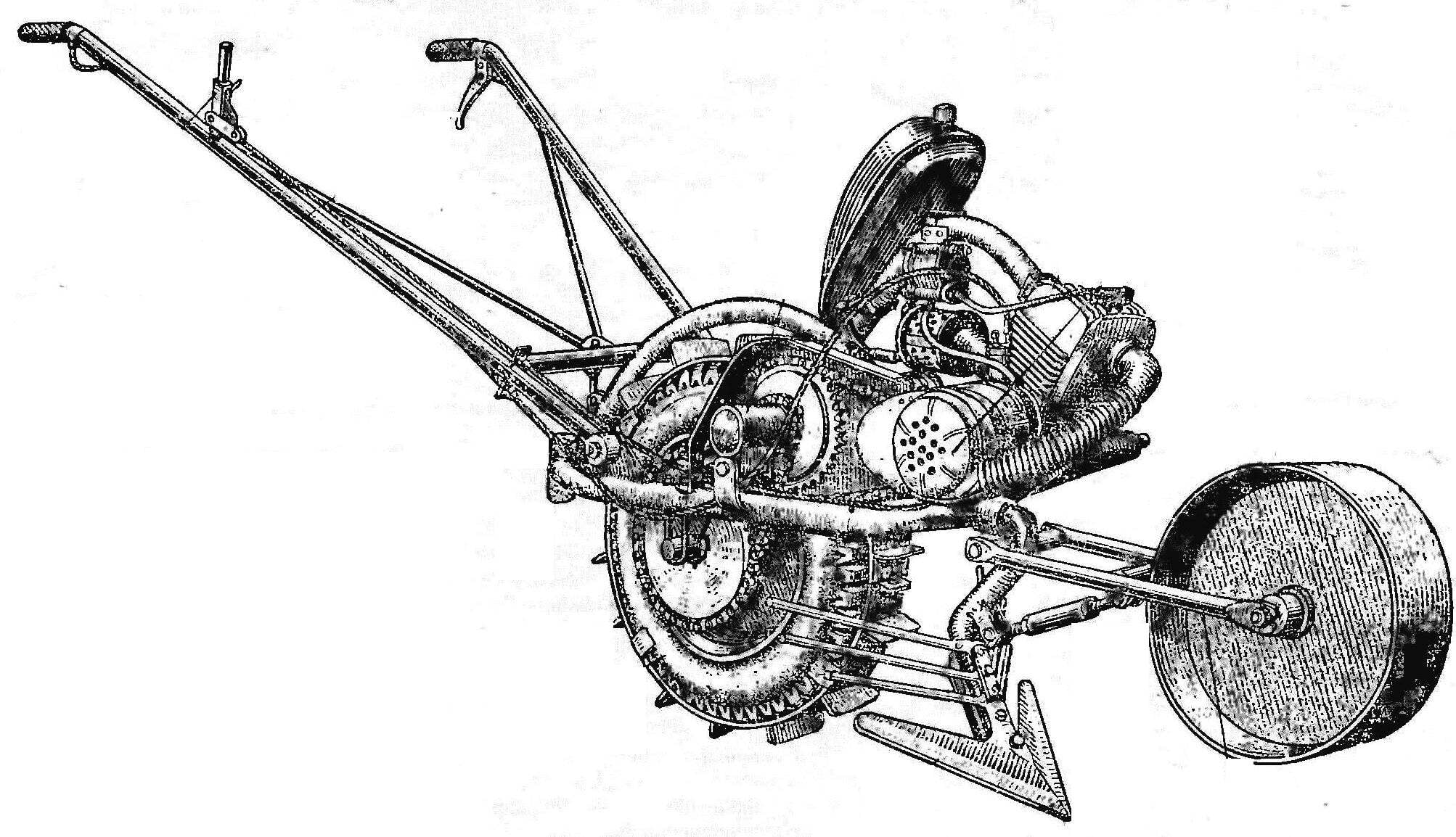
Fig: 1.General view of the walk-behind cultivation:
1 — throttle 2 — lever shifter, 3 — clutch lever, 4 — handle, 5 — frame, 6 — bracket rear mounted work tools, 7 — lugs. 8 — wheel, 9 — an intermediate node, 10 — tank, 11 — engine. 12 fan ring,13 — deflector cylinder, 14 — gauge wheel, 15 — a plug gauge wheels, 16 — adjusting rod 17 — paw cultivator.

 
Requirements for engine balancing scheme is also somewhat more rigorous: in addition to providing the necessary power and cooling, it should have small weight and dimensions. On my walk-behind tractor has an engine from a moped W-5V. Forced cooling — centrifugal fan, the impeller is mounted via made in the cover plate hole to the flywheel of the engine to the place of installation of the puller. The fan casing is made of thin sheet metal, has a Central inlet and tangential outlet that connects the corrugated hose to the vent on the cylinder. The necessary cooling of the engine can provide and the system with the blower motor on the basis of a DC motor (the brand MAN 12/5) with the impeller in a metal housing. When side mounted in the edges of the head will need to drill some through holes 15 d mm Voltage to the motor terminals is supplied through the diode rectifier mounted inside the fan shroud on the textolite plate, from the winding, lighting maggino you want to rewind a wire of smaller cross section, increasing the number of turns by half.
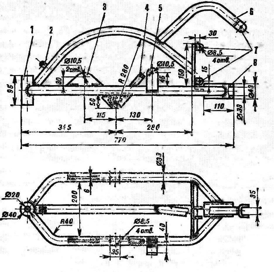
 
Fig. 2. Frame
Fig. 2. Frame:
1 — bracket, rear hitch, 2 — lug fixing screw focus control knobs. 3 — mounting plate handle, 4 — emphasis tensioner. 5 — bracket housing of the intermediate shaft 6. the upper engine mounts, 7 — place engine mounts, 8 — sleeve for front attachment of the working tool.
 
Frame of thick-walled steel tube ø 33 mm. of Its side arcs are welded on one side of the cut rough with the internal d 33 mm, oriented horizontally and on the opposite side in the vertical steel sleeve with outer ø 40 mm. the First is for the front installation of the working tool, and the second to be coupled to a two-wheeled trailer. Vertical steel strip 6 mm thick welded in the front part of the frame has the lugs for the engine mounts. The top engine mount welded to the vertical forms the arc of a tubular frame bracket. He also serves as a support for the installation of the fuel tank, borrowed from the bike and the ignition coil of type B-300.
 
Fig. 3. The hub of the drive wheel
Fig. 3. Wheel hub drive wheel
1 — hub bearing (180205). 2 — axis. 3 case 4 — flange mounting of the drive wheels, 5 star (2 – 39. step 15.87 mm).
 
On the side arcs Ramaswamy fixed plate bracket knobs, stops the wheel axis, bearing housing intermediate shaft and tilt stop tensioner Rear portion of the vertical arc is equipped with lifting eyes for focusing knobs Two pair of vertical through-hole d 8,5 mm in the lateral arcs of the frame are designed for ladders — two (J-shaped steel rods threaded at the ends, pressed to stops the axle of the drive wheel.
 
 
Fig. 4. A smart host
Fig. 4. Intermediate node:
1 — star engine transmission (from a moped “Riga”), 2 — STA. daughter of the gear train . 3 .— bearings No. 205, 4 — retaining rings. 5 — plug.
 
Controls serve two steel rough d 25 mm with their ends welded to the sleeve with a horizontal bolt hole M10. Among themselves they are connected by extensions of the steel bar ø 10 mm and cross tube, which is resistant hinge bolt to adjust the position of the handle. In the inoperative position the handle can be folded up. The arrangement of arms and levers of control — as is customary in motor vehicles: right-hand rotary knob is connected with the throttle valve of the carburetor, and the left lever — clutch of the engine. On the right side mounted shifter and rests of shells of ropes. The lever locks in three positions spring lock, which prevents the engine from damage when the spontaneous shifting.
 
Fig. 5. The impeller of the fan.
Fig. 5. The fan impeller.
 
Transmission of tillers is a two-stage chain gear. Torque output sprocket of the engine is transmitted by a chain with a pitch of 15.07 mm on the big sprocket on the intermediate shaft. Both sprocket — wheel transmission of a moped “Riga”. Then with a small sprocket of the intermediate shaft is transmitted to the wheel sprocket . Intermediate node, a shaft mounted on two bearings No. 205 in chiseled steel casing. As the hook both stars are located on one side of the shaft, for torque transmission, it is sufficient to connect them to the hub by welding instead of locking each of the sprocket on the shaft. The housing of the intermediate shaft connects to the bracket on the hinge to adjust its position in longitudinal and vertical direction. This gives you the ability to simultaneously tension both the chain gears. And in the desired position, the housing is fixed with a tensioning bolt, screw in the tilt stop frame.
 
Fig. 6. The thrust bolt handle.
 
The hub of the drive wheel is machined from a segment of thick-walled steel pipe ø 60 mm On the outer surface by welding reinforced sprocket mounting flange of the drive wheels. In the machined ends of the pipe sockets are mounted bearings No. 205. As the side load the wheel hub almost does not feel, for fixing bearings enough resciniti their outer race edge of the nest at 3-4 points.
 
The driving wheel may be any external d 540 mm with a width of 105 mm. this design used discs of 4.50—10 rubber scooter of 4.00—10.
 
Fig. 7. The control handle.
Fig. 7. Control knob.
 
The steel lugs of the drive wheel constitute two semi-rings are bent from a strip of 60X5 mm and connected to one side of the hinge, and the other coupling bolt M10. On the outside of the rib 14 welded to the steel strip 30X5 mm, folded at an angle of 45 To the Hoop wasn’t jumped from the wheel, each of the ends are welded on four side stops. If increased adhesion is not required, cleats are easy to remove from the wheel as they are mounted without decompression and inflating the tire.
 
Working tools — cultivators, plow, harrow, dozer blade, Shuttle cart and others — can be installed either behind or before a wheel cultivator. The figure shows the front cultivator with gauge device. The bracket arms of the cultivator is made of thick-walled steel pipe ø 33 mm. Below the tube bending did not wrinkle, this operation must be performed in a heated condition, after filling the internal cavity with sand. Mounted on the lower end of the bracket paw provides the cultivation of the soil without flipping it, and welded above the blade lattice of steel rods d 10 mm performs the function of Hiller.
 
Fig. 8. Cultivator-Hiller with gauge device
Fig. 8. Cultivator-Hiller with a copying device:
1 — grating blade of a mouldboard. 2 — paw cultivator. 3 — the adjusting Bush. 4 — the jockey wheel.

 
The ability to adjust and precise depth of tillage is achieved by a copying unit, consisting of a welded steel strip wheels, forks, bearing its axis and fixed on the bracket of the working body, and the adjusting gage. Her sleeve — tube ø 22 mm, internal thread M12 on one side — right, another — left. Two rods with the appropriate thread connects the plug to the wheel through the grommet With the bracket Thus, the rotation of the sleeve in the state or the other side changes the length of the thrust, and hence the position of the gauge wheels relative to the working tool.

Recommend to read

  • MAIN BATTLE TANK “ABRAMS”MAIN BATTLE TANK “ABRAMS”
    Large-scale work on designing a new main battle tank began in the USA after the termination in 1970 of the joint with Germany development of a promising tank МВТ70. In February 1972, the...
  • TUBULAR SHOVELTUBULAR SHOVEL
    Where conventional shovel passes in front of dense soil, this unusual diggers enter the ground like a knife through butter, though the effort inform her foot is almost the same. The...