ON TAKEOFF – THE PILOT

ON TAKEOFF - PILOTAttract the attention of athletes and spectators time the model is tailless. Most of them presented in the traditional competition “Experiment” in recent years, has a wing to direct the sweep and power system tractor or pusher propeller. However, this scheme has a number of inherent disadvantages. So, with the engine in front of the wing there is a need for additional balancing weight for balancing the tail model, the tail boom has to greatly increase to ensure a sufficient efficiency of the vertical stabilizer. And when using a power plant with pusher propeller there is a significant probability of hitting the hands of the athlete during the spinning propeller when starting Tierney.

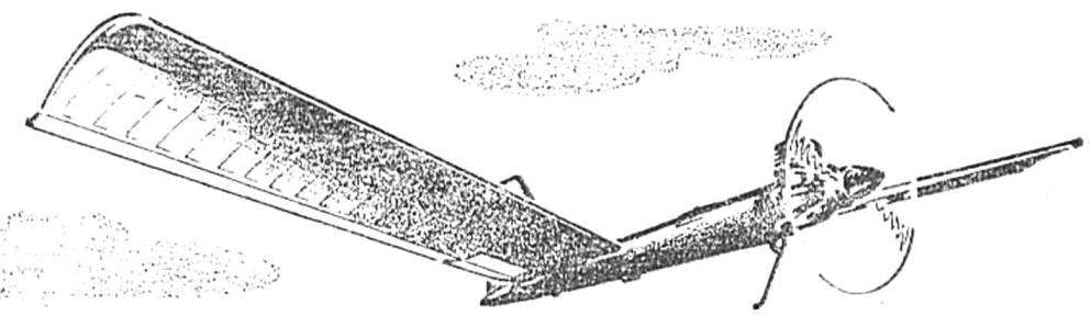
From these drawbacks could be eliminated by the scheme with forward-swept wing. It also allows you to get the model high flight performance. Thus, we propose timername “wing” consistently had three relatives on the geometry options, and they all helped the designer every time to become the winner of the competition “Experiment”. Studies have shown — to ensure that longitudinal balance of the machine with forward-swept wings rather small uniform positive twist and 4.5° (the profile of the wing is concave with a bent up tail, modified from the profile of Kupffer). The increase in the twist gives rise to losses for balancing model, which ultimately reduces its aerodynamic quality. The use of split two-piece wing with different angles of zaklinanie sections requires a lot of stability (i.e., greater aerodynamic twist), since the breakdown of the flow occurs in all sections simultaneously unlike the wing with a uniform twist. In the latter case, the failure gradually extends in size and the model manages to exit at small angles of attack before stalling at the corkscrew.
Time is flying in two modes — motor climb (active phase) and the cladding. Each of these stages dictates the terms of the balancing adjustment models should be separate for each flight mode. Tierney tailless scheme has its own characteristic features. The complexity of regulation and the lack of information about the aerodynamics of a particular device lead to ensure the smooth running of the spacecraft in the initial stage of overflights is extremely difficult. Therefore, the nodes in the model should have a high strength under impact design elements are required to rusticbeauty without damage of details of their attachment. And the wing hinge must have greater rigidity, since the bending of a swept wing there is an additional twist, sensitively affecting the longitudinal balance.
 
Fig. 1. Timer model airplane pilot class
 
Fig. 1. Timer model airplane pilot class:
 
1 — engine with a propeller, 2 — body, 3 — movement, 4 — wing, 5 — fairing, 6 — Kiel, 7 the rudder, 8 — adjustable stop 9 — the load rebalancing machine forced landing (a flight position, b — position when forced descent), 10 — flaps, 11 — adjustable stop.

 
Fig. 2. A typical wing section
 
Fig. 2. A typical wing section:
 
1 — hard shell, 2 — front spar, 3 — shelf, front spar, 4 — shelf rear spar, 5 — rear flange, 6 — fixed plate edges (of the flap).

 
Based on these requirements, the proposed timemay designed dvuhkonusnyj, with braces and a sewn toe. The lack of sharp corners and breaks in the power scheme of the longitudinal framing allows for greater strength and rigidity. The lining of forehead profile — balsa or shell is laminated of fiberglass or other synthetic fibrous material in two layers. The trailing edge is made of two layers of fiberglass glued between nipples stringer or pine slats with glued on her “knife.” made of aluminum of 0.3 mm thickness.
Each console is hinged on the fuselage by means of two bayonet plates. They were collected from three sheets of titanium or stainless steel with a thickness of 0.5 mm each, and fastened between the flanges of the spars with plywood linings. Console are fixed against slipping two rubber rings. Power frames of the fuselage, in the cavity which includes a bayonet plate, represent a plywood sheet duralumin (0,5 — 1,5 — 1,0 — 1,5 — 0,5 mm{. This design sample is good enough to perceive bending moments from the wing, while providing easy release of the strips from the fuselage upon impact model.
 
Fig. 3. Knot design hitch wing
 
Fig. 3. Knot design hitch wing:
 
1 — flat pin hitch console, 2 — wall (plywood 1 mm), 3 — beam flange, 4 — cowl, 5 — valve, b — tube fuselage, 7 — rib, 8 — pad (plywood 2.5 mm).

 
Fig. 4. The design of the adjustable hinge of the flap on the wing
 
Fig. 4. The design of the adjustable hinge of the flap on the wing:
 
1 — M2 screw adjust the position of the flap, 2 — spring, 3 — flap 4 — “pig”, 5 — wing.

 
The fuselage wikiepedia of three layers of synthetic fabric on a wooden disc and has the form of a pipe. The frames are mounted inside vyklicky with the help of the l-shaped contours (the contours of the same material of the fuselage]. Fairing and tail section double — layer vyklicky on the appropriate blanks. Keel celebarty, covered with one layer of fiberglass. He is joined by two spars with ribs.
 
Motor mount made integral with the fuel tank. Angle Vicosa the axis of the crankshaft is equal to down 6-3°. To minimize torque from the propeller thrust axis of rotation should pass through the center of gravity of the model. Finally, the angle Vicosa specified after complete Assembly Tierney. It is suspended over the axis of the motor vertical plumb line will set the desired position of the axis of rotation of the propeller.
 
To enable fine adjustment on the planning and on the mode of engine takeoff wing model equipped with two-position flaps with adjustable stops. On takeoff the flaps are fixed in the lower position due to the flexible rod fishing from the Sands of 0.5 mm; the cladding is in the upper position by a spring. Similar construction and have adjustable knots-position of the rudder. Separate adjustment of the end positions of the steering wheel and flaps for each flight mode allows to simplify debugging Tierney.
Flexible rods converge to the intermediate fuselage rocking, which is connected with timer to the elastic element from the yarn model of the rubber. In case of accidental impact the intermediate piece transfer (swing) is rotated, the races-at the same time thisa rubber thread, and fishing line running to the flaps, flies. Wings freely detach from the fuselage without damage to the control system flaps.
 
Forced landing due to rebalancing Tierney. In the flight position of the pendulum the cargo is held by a thrust of the timer. After the operation clockwork “pendulum” swung back rubber thread. Misalignment of the load weighing 40-50 g per 300 mm back allows you to change the alignment model ka 8-10%, which is enough to disrupt it in a flat spin.
 
Fig. 6. Under engine part of the fuselage
 
Fig. 6. Under engine part of the fuselage:
 
1 — frame-tank, 2 — tank’s cover, a 3 — fiberglass tube fuselage.

 
R and p. 7. The intermediate rocking ka the fuselage.
 
R and S. 7. The intermediate rocking ka the fuselage.
 
Adjustment model begins with the debugging planning. It is necessary to achieve an acceptable regime, starting with Tierney hills or tightening on the guard rails. After debugging the planning engine mount is glued into the fuselage. Thus due to the shortening of the forward fuselage select the position of the center of gravity of the machine. Alignment is roughly 20-25% of the average chord of the wing. Final testing of the treatment planning is made with the help of supports of the flaps and rudder. When you first take off the engine you need to set the flaps PA 8-10° downward relative to the position determined experimentally for planning. The maximum power should work at first, only 3-4 s. the Trajectory corrected by the takeoff flap deflection and steering. It is necessary to remember about high sensitivity Wake up “the wing” for all pereplanirovka caused by the increased efficiency located in the jet from the propeller rudders. The proper model is gaining 1120 — 150 m height for 12-15 with a steep rising hill.
 
MAIN FEATURES OF THE MODEL
 
Wing area, DM2 . . ………37,2
The angle of the cross-section, deg.:
at the root of the wing ……….0
at the end of the wing ………+ 4,5
The area of the flaps, DM2………..0,5X2
The area of the vertical stabilizer, DM2…..1,5
The area of the rudder, DM2…….0,17
Takeoff weight, g…………750
Weight of structural elements g:
wing (both consoles) ……..Z00
the fuselage (without motor) ……100
the engine Assembly ……. 270
clockwork . . …….30
the mechanism of the forced landing . . 50


O. VISHNITSKY

Recommend to read

  • FOX YOU ARE LOOKING FORFOX YOU ARE LOOKING FOR
    Radio, powerful or low-powered -- the Fox, which is so earnestly looking for "hunters" at the event. Low-power transmitters on one of the high-frequency transistor of the type ГТ308,...
  • PAPER POPRYGUSHKAPAPER POPRYGUSHKA
    Paper is the most affordable and "compliant" material for the manufacture of all kinds of toys — from boats-boats and pigeons until such unexpected figures as a jumping frog, about which...